Welcome to the Cypress page on element14. Here you can find things such as our latest news, training videos, and product details. Additionally, you can engage with us in our forums.
Previously related posts:
ModusToolbox Intro:
Part 1 link:
PSoC 6 BLE Pioneer Kit with Honeywell SEK002: Part 1
5. Blood Pressure Pump Board
https://my.element14.com/honeywell/sek002/eval-kit-board-mount-pressure/dp/2849208?COM=Cypress
The Honeywell SEK002 Sensor Evaluation Kit for Arduino is designed to assist in the evaluation of Honeywell ABP, MPR, HPM, and Humidicon sensors using the popular Arduino Header form factor. The SEK002 provides multiple on board solder pads for various surface mount devices as well as a DIP Header for a ABP sensor (S3) and a through hole SIP option for a Humidicon sensor (S7) as well as a header to plug in a cable from a HPM sensor (P4). The board offers both SPI and I2C to most sensors and UART with HPM sensors with the signals being mapped to the associated Arduino Header pins. Each sensor location on the board has an independent enable jumper and associated set of jumpers to enable either SPI of i2C for the sensor block on the board. However, there is no separate Chip Enable for the SPI interface and the Pressure sensors tend to have the same I2C address of 0x28 (40) which means that only a single Pressure sensor can be tested at a time with the board. There is an option where the customer can request to have a custom address assigned to a device, but the default for the Pressure Sensor is 0x28. The Humidicon sensor has an i2C address of 0x27 (39) so this sensor can be tested along with a Pressure sensor, but still only one Humidicon sensor can be tested at a time as an I2C device. Combining a I2C and a SPI sensor may be possible but this was not tested during this exercise. Instead of mounting sensors on the board directly, wires were attached the Humidicon and MPR sensor used in the test and attached to the connectors where the associated jumper would be placed for the sensor. This also provides the option to test a sensor that might be in another product or in an environment controlled area where it is not possible to mount the sensor on the SEK002.
As is shown in the top level image of the SEK002, the board is separated in 4 blocks: ABP Series Sensors, Micropressure Sensors (MPR), Humidicon Sensors, and HPM Series sensors.

In the bottom left of the image, there is a ABPDRRT005PG2A5 Pressure Sensor Amplified installed at S3 which is the initial sensor tested in this blog post.
To enable communication to this sensor, a jumper has been placed at J3, and to enable the I2C interface to the sensor jumpers have been placed on the left side of J4 and J5.
The bottom side of the SEK002 board has the Jumper settings to enable the I2C Communication for the HPM Series, ABP Series and Micropressue sensors as well as for the Humidicon SIP and SOIC options. Also, the SPI Communication for the ABP Series and Micropressure sensors is shown.

Quickview Video of the Honeywell SEK002
MPRLS0015PA0000SA - Pressure Sensor, 15 psi, Digital, Absolute, 3.6 VDC, Single Port, 1.7 mA
For the ABP type,
ABPDRRT005PG2A5 Pressure Sensor Amplified 5 psi Digital Gauge 5 VDC Dual Radial Barbed 3.7 mA
HIH8120-021-001 - Temperature and Humidity Sensor, HumidIcon Series, Digital, 0% to 100% RH, 2 %, SIP, Filter
https://www.element14.com/community/roadTests/1862
Honeywell provides evaluation software and custom Firmware for an Arduino UNO to test the SEK002 Sensor Evaluation Kit, however the Cypress PSoC 6 BLE Pioneer Kit (CY8CKIT-062-BLE) will be used to perform the sensor test in the post. The CY8CKIT-062-BLE has Arduino UNO style headers to the SEK002 can plug directly to the CY8CKIT-062-BLE to perform sensor evaluation. Since there is no provided code to test the SEK002 with the Cypress kit, test code will be created utilizing the PSoC 6 features of the CY8CKIT-062-BLE to read sensor values from the Honeywell sensors. Also, rather than use the PSoC Creator to program the PSoC 6 on the Pioneer kit, the ModusToolbox Software Environment will be used instead.

To run the test of the SEK002 the ModusToolbox IDE is used instead PSoC Creator. In a preview post. I covered an Overview of ModusToolbox and the i2C Master project from that post will be used as a starter project to test the sensors.
ModusToolbox Intro:
The CE221120 - PSoC 6 MCU SPI Master example is used in this post.
http://www.cypress.com/documentation/code-examples/ce221120-psoc-6-mcu-spi-master
To change the name of a starter project, ModusToolbox has an option available when right clicking on the 'mainapp' part of the project and selecting Rename ModusToolbox Application which will rename all of the files and folders to the new name.

The typical ModusToolbox starter project has 5 parts that make up the complete project.

The communication between the CY8CKIT-062-BLE and the Honeywell sensors through the SEK002, the i2C interface is used.
The Serial Communication Block (SCB) from the Device Configurator can be used to quickly configure either a
EZI2C, I2C, SPI or UART interface. The Device Configurator is accessed by double clicking on the
'design.modus' file under the config project folder.

Once the Device Configurator window opens, the SBC configuration is found under the Peripherals tab.

Since the I2C Master starter project was used, both a Master and Slave I2C SBC still exist.
However, the Master interface was moved to SBC 3 since this is tied to the main I2C interface on the
Arduino headers and thus the I2c interface used to communicated with the sensors.
Port 6 Pin 0 - Master SCL
Port 6 Pin 1 - Master SDA
To communicate with the Honeywell sensors, a buffer is created and set with 2 ACK and an NACK to be sent
to the sensor via the I2C Master interface.
uint8  tmpBuffer[TMP_PACKET_SIZE];
float pressureValue = 0.0;
uint16 cntVal = 0;

/* create packet to be sent to slave.  */
tmpBuffer[PACKET_SOP_POS] = CY_SCB_I2C_ACK;
tmpBuffer[PACKET_CMD1_POS] = CY_SCB_I2C_ACK;
tmpBuffer[PACKET_CMD2_POS] = CY_SCB_I2C_NAK;
The Master I2C is initialized and the status is checked to ensure the I2C interface initialized properly.
status = initMaster();

if(status == I2C_FAILURE)
 {
    handle_error()
 }
Then the Slave status is checked to ensure it is online and communicating,
if (TRANSFER_CMPLT == checkSlaveStatus())
{
    gpioState(&ledStates[RGB_RED], LED_ON);
    gpioState(&gpioStates[GPIO_MOTOR], ON);
    Cy_SysLib_Delay(START_PUMP_DELAY);
}
checkSlaveStatus
uint32_t checkSlaveStatus(void)
{
    uint32_t masterStatus;
     masterStatus = Cy_SCB_I2C_MasterSendStart(mI2C_HW, PRESS_SENSOR_ADDR, CY_SCB_I2C_WRITE_XFER, 100, &mI2C_context);
    if (CY_SCB_I2C_SUCCESS ==  masterStatus)
    {
        CyDelay(100);
        masterStatus= Cy_SCB_I2C_MasterSendStop(mI2C_HW, 100, &mI2C_context);
    }

    return masterStatus;
}
If the slave status is true, then the RED RGB Led will be lit and the Pump motor is turned on.
Then the sensor is read using the I2C Master Write interface. While the converted sensor value is less then 1,
the program will loop and read the sensor again until the value '1.00' is reached. The Pump motor is then turned off
and delays to normalize the reading. The Red RGB Led will blink while the sensor is being read.
while (pressureValue < 1.0)
{
    if (TRANSFER_CMPLT == readPressure(tmpBuffer, TMP_PACKET_SIZE, &pressureValue))
{

    UpdateLEDs(&ledStates[RGB_RED]);

    DEBUG_PRINTF("Pressure value =  %2.4f \r\n", pressureValue);
}

    if (BUTTON1_TOUCHED == getTouch())
    {

       break;
    }

    Cy_SysLib_Delay(RUN_PUMP_DELAY);
}

    DEBUG_PRINTF("\r\n\nPump Motor Stopping now \r\n");
    gpioState(&ledStates[RGB_RED], LED_OFF);
    gpioState(&gpioStates[GPIO_MOTOR], OFF);
readPressure Function
uint32_t readPressure(uint8_t* buffer, uint32_t bufferSize, float *pressValue)
{
    uint32_t masterStatus;
    uint8_t   tempBuffer[TEMP_PACKET_SIZE];
    static const uint8_t  pressureMask = 0xC0;
    uint8_t pressureStatus = 0;
    volatile uint32_t pressRawData = 0;
    uint8_t*   cmdBuffer = buffer;

    // Read the Pressure data
    Cy_SCB_I2C_MasterSendStart(mI2C_HW, PRESS_SENSOR_ADDR, CY_SCB_I2C_READ_XFER, 500, &mI2C_context);
    for (int bufNum = 0; bufNum < bufferSize; bufNum++)
    {
        masterStatus = Cy_SCB_I2C_MasterReadByte(mI2C_HW, cmdBuffer[bufNum], &tempBuffer[bufNum],  100, &mI2C_context);


        if(masterStatus != CY_SYSINT_SUCCESS)
        {
            return I2C_FAILURE;
         }
    }

    CyDelay(100);

    masterStatus = Cy_SCB_I2C_MasterSendStop(mI2C_HW, 100, &mI2C_context);

    if (masterStatus != CY_SCB_I2C_SUCCESS) {
         return I2C_FAILURE;
    }

    pressureStatus = tempBuffer[0] & pressureMask;
    switch (pressureStatus) {
    case 0:
        masterStatus = 0;
        break;
    case 1:
        masterStatus = 1;
        break;
    case 2:
        masterStatus = 2;
        break;
    case 3:
        masterStatus = 3;
        break;
    default:
        break;
    }

    // Convert the 2 byte data to 14-bits value

    pressRawData = (((uint32_t) (tempBuffer[0] & 0x3f)) << 8) | ((uint32_t) tempBuffer[1]);

    *pressValue = SSC_PRESSURE(pressRawData);

    return masterStatus = 0;
}
Pressure Sensor value convertion
#define SSC_PRESSURE(v)
((float)(v) * 1.6 / 16383)
For user input, the CapSense interface was added to the project. The CapSense interface on the CY8CKIT-062-BLE
includes a Slider, 2 Buttons as a presence sensor. Only the 2 Buttons were used for the testing of the sensor at this time.
To add CapSense to a ModusToolbox project, the first step is to enable the CapSense Peripherals System option
from Device Configurator.

Once CapSense is enabled, multiple pins must be enabled and configured.
In this instance, the CSX Sensing Mode is used with the following pin mapping.
| Name | Port[Pin] |
|---|---|
| Cmod | P7[7] |
| CintA | P7[1] |
| CintB | P7[2] |
| Button0_Rx0 | P8[1] |
| Button0_Tx | P1[0] |
| Button1_Rx0 | P8[2] |
| LinearSlider0_Sns0 | P8[3] |
| LinearSlider0_Sns1 | P8[4] |
| LinearSlider0_Sns2 | P8[5] |
| LinearSlider0_Sns3 | P8[6] |
| LinearSlider0_Sns4 | P8[7] |
From the Device Configurator, this will look like the following.

From the Pins tab in the Device Configurator, the individual pins can be configured.

Note where the P7[7] Terminals are set to CSD CapSense amuxbus_a and amuxbus_b.
A Clock will have to be enabled and configure for CapSense functionality which can be added
from the Peripheral Clocks tab. The 8-bit Divider 2 was added for CapSense.

Going back the Peripherals tab, the ModusToolbox also includes a CapSense Configurator
and CapSense Tuner to fine tune the CapSense configuration. These are added as
separate tool that can be launch from command line, but in ModusToolbox these have separate
Launch selections under External Tools. Selecting Launch CapSense Configurator will
open the CapSense Configuator tool.

From the BasicTab in the CapSense Configurator window, the CapSense devices can be added
and the Sensing mode set.
Here Button0 Button1 and LinearSlider0 have been added. The Buttons have the Sensing Mode
to CSX (Mutual-cap) where the Buttons can share the cap config.
From the Advanced Tab, the Widget Details can be accessed where the device settings can be fine
tuned and each port can be individually configured.

The Pins Tab will display the Signal and Port/Pin Mappings.

Once the settings are complete, clicking Save will save the config data and update the necessary
project files. This can be seen from the Code Preview window under Peripherals.

The required libraries to support the CapSense Interface can either be added manually or via the
ModusToolbox Middleware Selector by right clicking on the mainapp folder. Here the capsense library
was added to the mainapp folder psoc6sw-1,0->components->psoc6mw.

Borrowing code from another starter project, the CapSense interface can be initialized as follows:
void initCapSense(void)
{
    /*Initialize CapSense Data structures */
    Cy_CapSense_Init(&cy_capsense_context);

    /* Initialize CapSense interrupt */
    Cy_SysInt_Init(&CapSense_ISR_cfg, &CapSense_Interrupt);
    NVIC_ClearPendingIRQ(CapSense_ISR_cfg.intrSrc);
    NVIC_EnableIRQ(CapSense_ISR_cfg.intrSrc);

    /* Start CapSense block and perform first scan to set up sensor baselines */
    Cy_CapSense_Enable(&cy_capsense_context);
}
Example of reading a Button press from the CapSense interface
/* Check if CapSense is busy with a previous scan */

    if (CY_CAPSENSE_NOT_BUSY == Cy_CapSense_IsBusy(&cy_capsense_context)) {

 /* Process all widgets and read touch information */

 Cy_CapSense_ProcessAllWidgets(&cy_capsense_context);
 gestureStatus = Cy_CapSense_DecodeWidgetGestures(
 CY_CAPSENSE_LINEARSLIDER0_WDGT_ID, &cy_capsense_context);

 /* Button0 is active */

 if (Cy_CapSense_IsWidgetActive(CY_CAPSENSE_BUTTON0_WDGT_ID,

 &cy_capsense_context)) {

     currentTouchData = BUTTON0_TOUCHED;

 }
To show output of the Sensor reading, the serial Debug UART option was enabled.
To enable the Debug UART on the CY8CKIT-062-BLE, the Retarget I/O Middleware software must be added.
This is done by right clicking on the mainapp project folder and selecting the ModusToolbox Middleware Selector
option. This adds the Retarget I/O library files 'stdio_user.h' and stdio_user.c' to the project files.
Retarget I/O provides a means to send standard I/O commands such as 'printf' out a user defined Target such as the Debug UART
From the Middleware Selector window, ensure the checkbox for Retarget I/O is selected.

To enable the SBC UART for the Debug port (KIT_UART), open Device Configurator and
enable a SBC set to UART-1.0. SBC 5 was used in this instance.

From the Parameters pane, the UART Baud Rate, Comm Mode, etc can be set.

Also from the Parameters pane, the PIn mapping for Tx and Rx can be set as well as the
appropriate clock.
| Name | Connect |
|---|---|
| Clock | 16 bit Divider 2 clk |
| RX | P5[0] |
| TX | P5[1] |

The UART SBC can be assigned to the Tx and Rx from the Parameter pane.

Once the Debug UART has been configured, the code preview for the SBC can be viewed
from the Parameters tab.

Macros borrowed from another starter project were used to send commands to the serial port.
#include "cy_scb_uart.h"

    /***************************************
    *        Macros
    ***************************************/
    #define UART_DEBUG_HW        KIT_UART_HW

    cy_stc_scb_uart_context_t KIT_UART_context;

__STATIC_INLINE void UART_DEBUG_START(void) {
    (void) Cy_SCB_UART_Init(KIT_UART_HW, &KIT_UART_config, &KIT_UART_context);
    Cy_SCB_UART_Enable(UART_DEBUG_HW);
}


#define DEBUG_PRINTF(...)               (printf(__VA_ARGS__))

#define UART_DEBUG_GET_TX_BUFF_SIZE(...)  (Cy_SCB_GetNumInTxFifo(UART_DEBUG_HW) + Cy_SCB_GetTxSrValid(UART_DEBUG_HW))

#define DEBUG_WAIT_UART_TX_COMPLETE()     while(UART_DEBUG_GET_TX_BUFF_SIZE() != 0);
To send a string or data to the Debug serial port, the DEBUG_PRINTF macro is used.
UART_DEBUG_START();
DEBUG_PRINTF("\r\n\nWait for User input to start \r\n");
DEBUG Uart output example:

Debug output while reading pressure sensor

To test the pressure sensor capabilities, a Mini Pump and Solenoid Valve along with a modified manual
Sphygmomanometer were used.
Mini Air Pump Motor Model : KPM12A
Solenoid Electromagnet Valve
A circuit board to power the Pump and Valve was created using 2 TIP120 transistors.

The following Pin Mapping were used to control the Motor, Valve and RGB LEDs.
| Name | Port[Pin] |
|---|---|
| VALVE_OUT | P6[3] |
| MOTOR_OUT | P9[7] |
| RGB_RED | P0[3] |
| RGB_GREN | P1[1] |
| RGB_BLUE | P11[1] |
To enable the configurator devices, the 'init_cycfg_all' function is called.
init_cycfg_all();
A set of enums and struct/struct arrays are used to control the states of the Motor and Valve and the LEDS.
typedef enum {LED_OFF = 1u, LED_ON = 0u} LED_STATE;

typedef enum {RGB_RED, RGB_GREEN, RGB_BLUE, KIT_LED2_RED} RGB_COLOR;

typedef enum {GPIO_MOTOR, GPIO_VAVLE} GPIO_STATE;

typedef  struct Gpios{
    GPIO_PRT_Type* portNum;
    uint32         pinNum;
    uint32         pinState;
}Gpio;

Gpio ledStates[4] = {
        {RGB_RED_PORT, RGB_RED_PIN, LED_OFF},
        {RGB_GREEN_PORT, RGB_GREEN_PIN, LED_OFF},
        {RGB_BLUE_PORT, RGB_BLUE_PIN, LED_OFF},
        {KIT_LED2_PORT, KIT_LED2_NUM, LED_OFF}
};

Gpio gpioStates[2] = {
        {MOTOR_OUT_PORT, MOTOR_OUT_NUM, OFF},
        {VALVE_OUT_PORT, VALVE_OUT_NUM, OFF}
};
Functions to control the state of the GPIO devices and LEDs.
void UpdateLEDs(Gpio *ledState)
{

    ledState->pinState = (LED_OFF == ledState->pinState) ? LED_ON : LED_OFF;

    Cy_GPIO_Write(ledState->portNum, ledState->pinNum, ledState->pinState);
}

void gpioToggle(Gpio *gpioVal)
{

    gpioVal->pinState = (OFF == gpioVal->pinState) ? ON : OFF;

    Cy_GPIO_Write(gpioVal->portNum, gpioVal->pinNum, gpioVal->pinState);
}

void gpioState(Gpio *gpioVal, uint8 gpioState)
{

    gpioVal->pinState = gpioState;

    Cy_GPIO_Write(gpioVal->portNum, gpioVal->pinNum, gpioVal->pinState);
}
To turn off a GPIO device such as the Motor or Valve, the device enum value and state is sent to the gpioState function.
gpioState(&gpioStates[GPIO_MOTOR], OFF);


gpioState(&gpioStates[GPIO_VAVLE], OFF);
The code waits for the user to press Button0 on the CapSense interface to start the pump and read the pressure sensor.
DEBUG_PRINTF("\r\n\nWait for User input to start \r\n");

while (BUTTON0_TOUCHED != getTouch())
{
   Cy_SysLib_Delay(500UL);
   UpdateLEDs(&ledStates[RGB_BLUE]);
}

gpioState(&ledStates[RGB_BLUE], LED_OFF);

DEBUG_PRINTF("\r\n\nPump Motor Turning on \r\n");

if (TRANSFER_CMPLT == checkSlaveStatus())
{
   gpioState(&ledStates[RGB_RED], LED_ON);
   gpioState(&gpioStates[GPIO_MOTOR], ON);

   Cy_SysLib_Delay(START_PUMP_DELAY);
}
The Pump will run until the pressure sensor reading reaches 1, and then the pump state is set to OFF.
while (pressureValue < 1.0)
{
    if (TRANSFER_CMPLT == readPressure(tmpBuffer, TMP_PACKET_SIZE, &pressureValue))
    {

        UpdateLEDs(&ledStates[RGB_RED]);

       DEBUG_PRINTF("Pressure value =  %2.4f \r\n", pressureValue);
    }

   if (BUTTON1_TOUCHED == getTouch())
   {
      break;
   }
   Cy_SysLib_Delay(RUN_PUMP_DELAY);

}

DEBUG_PRINTF("\r\n\nPump Motor Stopping now \r\n");

gpioState(&ledStates[RGB_RED], LED_OFF);
gpioState(&gpioStates[GPIO_MOTOR], OFF);

Cy_SysLib_Delay(CMD_TO_CMD_DELAY);
After the pump state is set to OFF, the sensor value is checked again and the pump is used to attempt to keep the
the pressure value at 1 for 10 iterations.
for (cntVal = 0; cntVal < 10; cntVal++){

   if (TRANSFER_CMPLT == readPressure(tmpBuffer, TMP_PACKET_SIZE, &pressureValue))
   {
        UpdateLEDs(&ledStates[RGB_GREEN]);

        DEBUG_PRINTF("Pressure value =  %2.4f \r\n", pressureValue);

      if (pressureValue < 1.0 )
      {
          gpioState(&gpioStates[GPIO_MOTOR], ON);
      } else {
          gpioState(&gpioStates[GPIO_MOTOR], OFF);
      }

       Cy_SysLib_Delay(RUN_PUMP_DELAY);
  }
}
The last part of the test is to release the pressure from the cuff.
DEBUG_PRINTF("\r\n\nRelease Pressure \r\n");

 gpioState(&ledStates[RGB_GREEN], LED_ON);
 gpioState(&gpioStates[GPIO_MOTOR], OFF);

 gpioState(&gpioStates[GPIO_VAVLE], ON);

 for (cntVal = 0; cntVal < 3; cntVal++) {

     Cy_SysLib_Delay(START_VAVLE_DELAY);
 }

 gpioState(&gpioStates[GPIO_VAVLE], OFF);
 gpioState(&ledStates[RGB_GREEN], LED_OFF);

 Cy_SysLib_Delay(CMD_TO_CMD_DELAY);
Video of the ModusToolbox config used and a running example of reading the ABP sensor from the SEK002 board using a Cypress PSoC BLE Pioneer kit.
The Honeywell SEK002 is a handy board that can be used to quickly test the Honeywell line of SPI and I2C and HPM sensors, or other related sensors. The board has multiple options for the various mounting footprints which include both surface mound and DIP. The Arduino Headers allow the board to be used with low cost Arduino style dev kits where testing can be rapidly prototyped. One consideration is that the default address for many of the Honeywell sensors have an I2C address of 0x28(40) so only 1 sensor can be tested at a time. However, if the sensors support both SPI and I2C, then at least 2 can be tested with each other. Also, considering the small form factor of some of the Surface Mount pads, it is unclear as to how a sensor could be mounted to the board in this manner since heating the board could cause the components on the bottom side of if to either move or fall off. A Hot Air tool might be an option in this case. Overall, it is a nice platform to quickly evaluate Honeywell sensors in a common Arduino config.
To see about adding FreeRTOS and BLE and the E-Ink Display and mobile reading of the sensor.
Back a few months back, Randall posted a discussion looking for folks to test the Honeywell Sensors with the SEK002 Sensor Evaluation Kit For Arduino with the Cypress PSoC BLE Pioneer Kit and I had volunteered to give it a go at the time of the posting. However, due to a number of computer issues and other life events that I have had to attend to recently, I was not able to work on this until now.
The initial post for this was:
This is what I proposed:
For my testing, I intend to create a portable Blood Pressure/Vital Sign monitor that uses the Cypress PSoC 6 BLE board where the BP values are shown on the E-Ink display. Also, using the BLE capabilities of the PSoC 6 kit, I would use this to display the values from a remote connected BLE device; a web site would be created if time permits. The Blood Pressure Monitor would include a pump powered Sphygmomanometer that the user would apply to am arm to read their Blood Pressure and the Honeywell sensor would be used to translate this value to a Blood Pressure value. Being portable would be important, so the Li-Po capabilities of the BLE Pioneer kit would be used to power the kit; it is unclear at this time if the pump could be powered from this or if an separate power source would be needed.
The testing of the Humidity Sensor, if required, would involved recording the environmental conditions around the user which would be displayed on the E-Ink display.
The Test configuration for testing the Honeywell sensors and SEK002 include the following:
Cypress PsoC 6 BLE Pioneer Kit (CY8CKIT-062-BLE)
https://www.element14.com/community/roadTests/1862
SEK002
https://my.element14.com/honeywell/sek002/eval-kit-board-mount-pressure/dp/2849208
MPRLS0015PA0000SA - Pressure Sensor, 15 psi, Digital, Absolute, 3.6 VDC, Single Port, 1.7 mA
For the ABP type,
ABPDRRT005PG2A5 Pressure Sensor Amplified 5 psi Digital Gauge 5 VDC Dual Radial Barbed 3.7 mA
HIH8120-021-001 - Temperature and Humidity Sensor, HumidIcon Series, Digital, 0% to 100% RH, 2 %, SIP, Filter
Mini Air Pump Motor Model : KPM12A
Solenoid Electromagnet Valve
Flexible Tubing
Penn Plax Airline Tubing for Aquariums –Clear and Flexible Resists Kinking, 25 Feet Standard
Dixie Ems Deluxe Aneroid Sphygmomanometer Blood Pressure Cuff, Black
Sold by: BP MEDICAL SUPPLIES
2 x TIP120 for powering Valve and Pump.
2 x 10k Resistors
2 x 1N4004 diodes
LED and 330 Ohm resistor for Light indicator
Cypress ModusToolbox 1.0
http://www.cypress.com/products/modustoolbox-software-environment
Segger emWin Bitmap Converter, Demo version (For Creating e-Ink Graphics)
https://www.segger.com/downloads/emwin/


Left to Right
 Series
ABPDRRT005PG2A5 - Pressure Sensor, Amplified, 5 psi mounted on SEK002 which is mounted on the PSoC 6 BLE Pioneer Kit.

Attempt to solder wires to MPRLS0015PA0000SA - Pressure Sensor. This sensor is very small and really is intended for surface mount placement.
This was a bit of challenge to do with a standard soldering iron, but after a bit I was able to get it to stick. After soldering the wires, I covered the connection with hot glue in hopes that the wires would not pull off.

Mini Air Pump and Solenoid Electromagnet Valve with TIP120 for powering devices

Mini Air Pump and Solenoid Electromagnet Valve tube connections.

Pump assembly connected to PSoC 6 BLE Pioneer Kit with SEK002 and Pressure Sensor, Amplified and ARM cuff with 3.7 volt Li-Po for power. The Li-Po is used to power the Pump and the Valve assembly and the board was powered via USB Type-C during development and debug. When the test is run, the pump will start inflating the bladder in the cuff and once the pressure value read by the Honeywell Pressure sensor gets to 1, the pump stops and the valve engages releasing the air.

The software used to test the Honeywell SEK002 and sensors will include the ModusToolbox IDE and PSoC 6 SDK. This will include:
An overview of the ModusToolbox can be found at the following:
Part 2 of this blog will cover the software configuration.
Cypress has a new PSoC 6 tool in town and it's called ModusToolbox. ModusToolbox is a development environment for the PSoC which includes the PSoC SDK, ModusToolbox IDE and Cypress Programmer. The PSoC 6 SDK includes the standard Cypress tools such as PSoC PDL API (based on PDL 3.1), Middleware Libraries, Command-Line Tools, fw-loader, PSoC 6 MCU Configurators, CapSense and more.
Link to ModusToolbox site:
http://www.cypress.com/products/modustoolbox-software-environment
Image from the ModusToolbox Release Notes:
http://www.cypress.com/file/455206/download

The PSoC 6 Software Library (psoc6sw-1.0) is comprised of two main pieces; Peripheral Device Library (PDL) and middleware/software libraries.
The main interface is the ModusToolbox IDE which is an Eclipse based product which means it includes the standard features of the Eclipse IDE plus some extra tools specific to the Cypress PSoC 6 devices.
The following is a partial list of some of the features available in the current release of ModusToolbox (1.0)
Currently, ModusToolbox 1.0 supports all PSoC 6 MCU architecture devices.
The kits supported with this ModusToolbox version include:
NOTE: ModusToolbox requires KitProg3 so a firmware upgrade may be required.
GUI -based Configuration tools called Configuators are included as part of the SDK and can be run either from the ModusToolbox IDE or from command-line:
Configurator: Configure Smart I/O settings and generate the required firmware.
The following utilities are available with the SDK:
To install ModusToolbox, the tool can be downloaded from the Cypress web site at:
http://www.cypress.com/products/modustoolbox-software-environment
NOTE: ModusToolbox is only supported on the following 64-bit operating systems
NOTE2: There is no 32-bit support
After installing ModusToolbox, open the tool by double clicking the Desktop Icon; that is if running Windows and there is a shortcut created.

When ModusToolbox first starts, a slash screen appears.

After the splash screen appears, as in a standard Eclipse IDE, the user is prompted to either open or create a workspace.

NOTE: For users with a Cypress PSoC 6 BLE Pioneer Kit (CY8CKIT-062-BLE) earlier than rev 13, the startup file from the PDL folder must be replaced otherwise the code will not run on the kit.
See the data at the following link for info on how to perform this.
https://community.cypress.com/thread/42859?start=15&tstart=0
This will be located at the following location:
C:\Users\<MyUserName>\ModusToolbox_1.0\libraries\psoc6sw-1.0\components\psoc6pdl\devices\psoc6\startup\gcc
When ModusToolbox finally launches, it starts with a Welcome screen that includes links to help get started with the tool

If this page is closed. then the blank IDE screen can be seen where a new project can be created or imported from an existing project.

Under the Project Explorer Pane, there is a section with the ModusToolbox IDE logo in it. In this section, click on the Quick Panel tab and two Start options are shown; New Application and Search Online for Code Examples.
Click on New Application and a screen to Choose Target Hardware appears with an options for Dev/Eval Kit or Custom Hardware are seen.

The Custom Hardware option is for use when a new custom application is being created. The Dev/Eval Kit option can be used to access starter examples for the supported PSoC 6 boards.
In this example, the Dev/Eval Kit option will be used.
Once the Dev/Eval Kit option is selected, a screen will appear listing the supported board for ModusToolbox.

The CY8CKIT-062-BLE kit will be used in this example. Select CY8CKIT-062-BLE from the list and click Next.

The CE221120 - PSoC 6 MCU SPI Master example is used in this post.
http://www.cypress.com/documentation/code-examples/ce221120-psoc-6-mcu-spi-master
Download and unzip the file from the link and use Browse Button from the Starter Application window to select this modus.mk file and click open.

After clicking Open, the CE221120_HighLevelSPIMaster project will appear in the application selection pane.

Highlight this example and click next and the Summary window will appear.

If all looks correct, click Finish and the project will be loaded into the ModusToolBox IDE


From the imported project, 5 folders are created.
Since this is a Starter Project, there are a few items that need to be adjusted in the project before it will work with the PSoC 6 BLE Pioneer Kit.
There is a PDF document in the CE221120_PSoC6_SPIMaster titled CE221120_PSoC6_SPIMaster.pdf which describes the necessary changes required in the project.
This can be downloaded from the Cypress website as well:
http://www.cypress.com/file/455556/download
The first thing to note is the Hardware Setup which notes the KitProg on the BLE Kit must be at rev KitProg3 before it can be used with the ModusToolbox.
Also, the Hardware Setup describes how to connect the Slave and Master SPI signals from the Arduino Headers on the kit.

In the Resources section of the CE221120 doc, the ModusToolbox Resource are shown. In particular a DMA Channel has to be added to the project with the Alias txDma.

For the CY8CKIT-062-BLE, a DMA DataWrite 0 Channel 0 is required.

To add a DMA channel ModusToolbox project, the Device Configuator is used.
This can be launched by either double clicking the 'design.modus' file or clicking 'Configure Device' under the ModusToolbox Quick Panel.

Once the Device Configurator is open, click the DMA tab to add a DMA Channel.
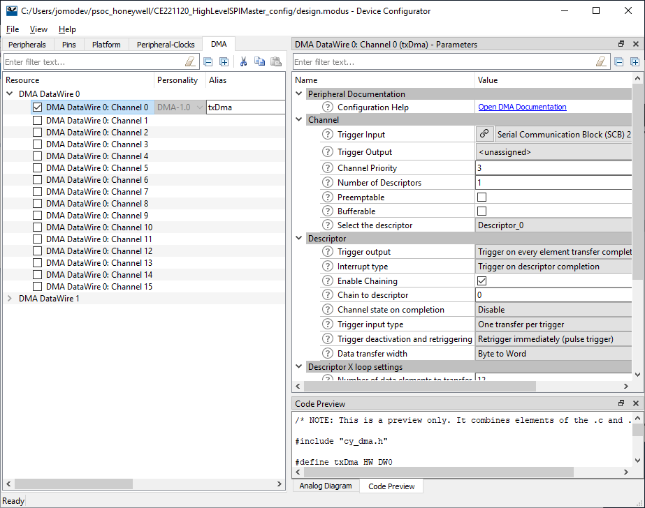
See Figure 4. txDma Resource Configuration from the CE221120 doc for the proper settings.
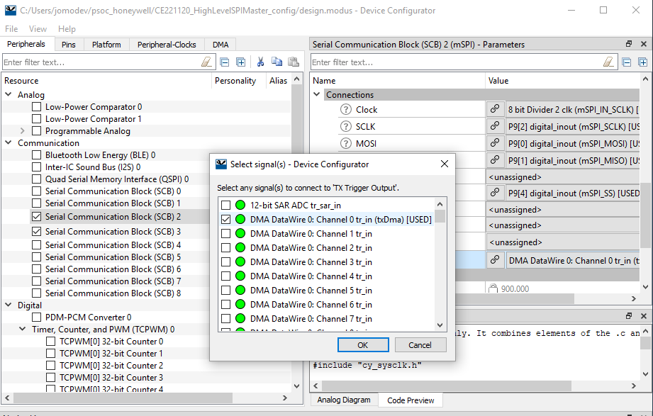
Once the DMA channel is added, this needs to assigned to the appropriate SBC. In this case it is the SPI Master SBC 2 where it is used to send the data to the SPI Slave. Also, note the other settings for SBC 2 as described in the CE221120 doc.

The SCBs can be accessed via the Peripherals Tab in the Device Configurator and assigning it to TX Trigger Output under Connections.
The SPI Slave SBC 1 connections are configured as follows.

The SBCs can be configured as either a EZI2C, I2C, SPI or UART from the drop down list box the right of the Communication listing of each SBC.

The KIT_LED2 (RED LED at LED9 Port 13 Pin 7) may need to be configured if not already set. This is used to indicate that the data transfer between the Mast and Slave SPI interfaces has completed. This is under the Pins tab in the Device Configurator tool.

The SBC and LED Pins assignments are as seen here:

Ensure the clocks listed under the Peripheral-Clocks tab are set as follows:

Under the Platform Tab, the Debug port assignment is set to SWD mode.

Once all of the changes are made in the Device Configurator, Save the changes and close the tool.
One note, as previously mentioned, before the project is built, it is best to replace the startup file with the updated one from the Cypress Community posting.
https://community.cypress.com/thread/42859?start=15&tstart=0

In the ModusToolbox IDE, it is best to clean the project if changes are made in Device Configurator to ensure no leftover configurations are still active. This can be performed by clicking
Clean CE221120_HighLevelSPIMaster Application
under the Quick Panel tab and CE221120_HighLevelSPIMaster_mainapp selection.
After cleaning the build, it is best to Rebuild the Index for each project folder. This is performed by right clicking on a project folder and selecting 'Index' Then 'Rebuild' to rebuild the Index. Then right click the project folder again and select 'Index' and then ' Update with Modified files'.
Then build the project. This can be performed by clicking
Build CE221120_HighLevelSPIMaster Application
under the Quick Panel tab and CE221120_HighLevelSPIMaster_mainapp selection.

Once the program builds successfully, there are two options the load the code on the PSoC 6 board; Debug or Program with either a J-Link or programmer or the builtin KitProg3 programmer. These are listed under Launches in the Quick Panel.

As in a typical Eclipse IDE, if the Debug option is used, then the Debug session will be started allowing the code to be stepped through one line at a time or adding a Breakpoint to stop the code at a particular point. If the example was configured properly, the KIT_LED2 will blink each time the code completes a loop through the data transfer or every 1 sec if the code is loaded on the board.
Example of a Debug session.

Once the code is running properly, the KIT_LED2 should blink every second indicating the data transfer was completed.
This is a quick video showing the example running on a PSoC 6 BLE Pioneer kit rev. 8.
The ModusToolbox 1.0 from Cypress is a very capable tool that adds and option to programming a PSoC 6 device using a standard IDE. The SCBs (Serial Communication Blocks) are quite useful and easy to set-up to add either a SPI, i2C, or UART to a project. I have just scratched the surface of this tool and plan to use it in a project I am working to see if will suite my purposes to program the PSoC. I have yet to test any C++ code with this, but I would suspect that it is an Eclipse based tool that C++ should be supported. That will be my next test with this.
Enjoy.

This is part 2 of my 2-part blog, showcasing my Honeywell pressure sensing application using a PSoC 6 BLE Pioneer kit.
Part 1, which introduces the Honeywell SEK002 sensor shield and the sensors used, can be found by clicking here.
The origins of this project started with a post made by Randall Scansy, back in September 2018, for requesting someone to:
"Interface the pressure sensors of the Honeywell Sensor Shield with the PSoC 6 analog/digital peripherals and then transmit data via BLE or showcasing it on the E-ink display of the PSoC 6 BLE Kit. The project should have some kind of medical application. For example, measuring pressure in some kind of health/medical application."
As a reply to Randall's request I proposed to attempt the following:
"As such, I felt that creating an infusion device would be an achievable means to demonstrate the application of a pressure sensor in the medical sector. I can readily create my own manual test apparatus to demonstrate this syringe infusion technique, as all it requires is a large syringe with a small pressure sensor inserted in the base of the syringe. I can then measure the diameter of the outlet nozzle which then allows me to gauge force while ignoring any likely fluid compression for now. I then thought that if I add in capacitance measurement, which I can do with a PSoC 6 device, together with the pressure sensor, I should then be able to gauge the liquid flow rate as well as determine the dynamic viscosity of the liquid. I believe that in quite a few medical scenarios, fluid or liquid viscosity is an important parameter and any automated equipment would need to stop should viscosity fall outside a defined tolerance, for example. A further, nice to have, would also be a suitable Honeywell temperature and humidity sensor, as theoretically temperature needs to be measured when taking viscosity measurements. "
In part 1, I set out my PSoC 6 project application workflow, which set out 7 key steps to completing the PSoC 6 firmware that would read humidity, temperature and pressure sensor data and display this data periodically on the eInk display shield as well as provide a BLE bridge to allow this data to be transferred to another device. Here is that workflow again:

What is not covered in my project application write-up is the capacitive sensing part.
| {gallery:autoplay=false} My Liquid Level Prototypes |
|---|
|
|
This proved more of a "design challenge" for me, as I have never designed a liquid level sensing application before.
As I did not have the correct material to create the right capacitive sensing "pads" using copper strips or foil (or conductive ink), I tried single core copper wire instead, but my initial test apparatus failed to show anything of value. So, I decided to park this part of the project for another day.
One thing that did work was my aluminium foil shielding, which is under the duct tape (see picture). When I held the syringe no change in capacitive readings were detected - I used the PSoC Creator Capsense Tuning Tool for this test.
Needless to say, the rest of the project is complete and hence this blog post. So let's start with a video demonstration and then I will complete with a project walk through.
Apologies for quality of the audio. This is a bootstrap setup using a Amazon Fire tablet (microphone is not great at all).
Thanks to Cypress Semiconductor there is a great range of PSoC 6 examples to work with.
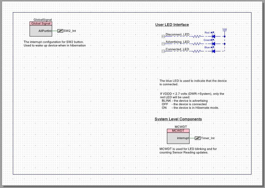
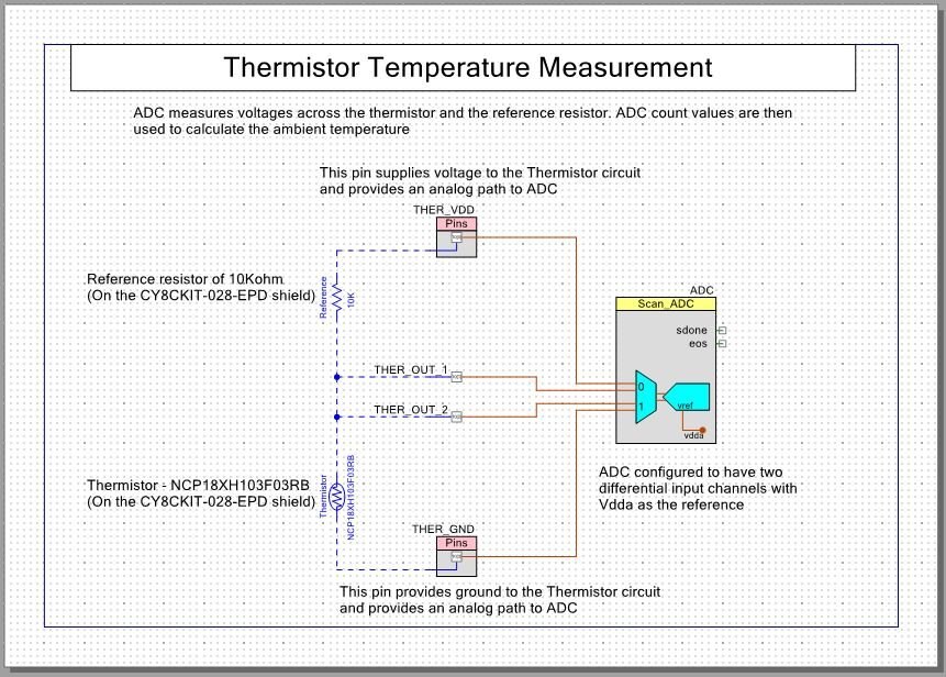
I have incorporated different code snippets within my project, such as the BLE callback function, watchdog timer routine, eInk display (EPD display shield), temperature measurement from the EPD display shield thermistor, CapSense button detection and various other user interface routines such as LED control and SW2 wakeup.
| {gallery:autoplay=false} PSoC Creator Top Level Design View |
|---|
|
|
|
|
Let's start with the Bluetooth 5.0 component.
Here we have it set up as a peripheral device. It is using both of the PSoC 6 cores. CM0+ handles the BLE interrupt timer and CM4 handles the logic for the defined profiles and exchange of information.
The BLE component acts as a GATT server and we have defined an Automation IO service (0x1815), which exposes an Analog characteristic (UUID: 2A58). For this characteristic I chose to use the NOTIFY property only. The Automation IO service also uses the Characteristic Descriptors to define what the Analog value means. This is very useful for information exchange between the central device and the peripheral device.
| {gallery} Automation IO Characteristic Descriptors |
|---|
|
|
For the purposes of my application, I defined my units as "unitless" (to make it simpler for my smartphone app - I transmit the raw 16bit value), but I could easily have defined the correct units and then transmitted the actual pressure value (note that for float variables this requires a specific conversion technique).

Moving onto the UART component.
Here I followed this Cypress Semiconductor tutorial: https://www.youtube.com/watch?v=ZJOF2f423nI
This tutorial provides guidance on how to use "printf" by enabling the "Retarget I/O" option in Build settings and then amending the shared "stdio_user.h" file to define the UART port.

For the I2C Sensor Bus, we include a I2C Master component.
Not much needs amending here. In my case I used the 100kHz as my data rate (I could have used 400kHz).
Other Code modules
These are all direct copies off PSoC 6 examples found via PSoC Creator, so does not warrant additional comment as all examples I have used are very well documented.

For the Bluetooth Low Energy bridge, I created a smartphone app, using MIT AppInventor as I was able to use an old project of mine, which is listed on Hackster.io.
I have attached my PSoC 6 Code and I have uploaded my the MIT Appinventor project onto Github (as the Element14 website will not accept as an attachment) for those who want to look at and/or use.

The SEK002 Sensor Evaluation Kit consists of an Arduino R3 compatible shield and some software, which includes firmware for an Arduino and a Windows-based software application for reviewing live data on a laptop or PC.
But, we all know that an R3 compatible sensor shield is not just for Arduino, as most will work perfectly with the PSoC 6 BLE Pioneer Kit, or with any other development board that uses the R3 compatible pin configuration. It is only the Arduino firmware and the windows software executable that are not compatible with the PSoC 6 straight out the box. Anyhow, this firmware and software is not needed to produce creative PSoC 6 based applications.
So let's get started.

Image source: Honeywell datasheet.
The SEK002 R3 sensor shield provides compatible SMD footprints and through-hole SIP/DIP connectors to allow the user to test and evaluate the following Honeywell sensors:
Digital Humidity/Temperature Sensors (HIH6000, HIH6100, HIH7000, HIH8000, & HIH9000 Series) – which I’ve marked as zone 1 (see below);

The area marked as zone 5, is for power selection. Here, the user must use a jumper (shunt) to manually select either 3v3 or 5v as the operating voltage for the shield.
If you are unfamiliar with the board, it is worth your while watching this YouTube video from John Lachenmayer (introduces himself as a Honeywell Field Application Engineer). This video provides a nice overview of the Arduino R3 shield and introduces the different sensors that can be attached to the shield. It also demonstrates how to use the shield using an Arduino micro-controller and then focuses on the Honeywell analytical software, which is not applicable in our case.
One thing to note about the shield is that it is designed to allow the user to manually enable any sensor that has been mounted on the board via a jumper (shunt). The user is then also required to enable and select whether the sensor communicate via I2C or SPI. These are marked as follows:

The big surprise I had with the sensors I ordered was how small they all were.

Let’s look at these sensors in more detail.
Digital Humidity/Temperature Sensor (HIH8000 Series)
The Honeywell HumidIcon Digital Humidity/Temperature Sensor is a digital output-type relative humidity (RH) and temperature sensor combined in the same package. The sensor provides a ±2.0 %RH accuracy and a ±0.5 °C Temperature accuracy. The temperature sensor has a -40 °C to 125 °C [-40 °F to 257 °F] operating temperature range and the humidity sensor natually operates in the 0% to 100% RH range. The sensor operating voltage is 2.3 Vdc to 5.5 Vdc. The sensor consumes only 1 μA when it goes into sleep mode, following a measurement, versus 650 μA when taking measurements.
The user can choose a sensor based on the following options:
The specific sensor I ordered was the HIH8120-021-001 sensor, which operates as an I2C slave (address 0x27 with a 14-bit resolution for both humidity and temperature measurements), it does not have a hydrophobic filter (see photo) and it comes in a SIP 4-pin package.

To obtain a measurement from the sensor, you first make a “measurement request”. This is done by simply sending an I2C WRITE command, as illustrated:

Image source: Honeywell Technical Note on I2C communication with HumidIcon Sensor
The sensor will, according the datasheet, then take 50-60ms from power-up, i.e. when the write request is received, to when data is ready to be read.
To read the data, you simply send a READ command and then send an ACK after every byte read and then a NACK and a STOP command to say “that is all, thanks”.


Image source: Honeywell Technical Note on I2C communication with HumidIcon Sensor
To test the validity of the data received, you then need to read the Status Register (S1 & S0) values. The following conditions can apply:
As shown in the diagrams above, both the humidity and temperature values are stored in 2 bytes each. You are then required to do some bit match to obtain the 14-bit values. Then it is a matter of applying formulae to covert the 14-bit value in %RH and temperature in degrees Celsius. A further conversion is required for a temperature in degrees Fahrenheit.
According to the Honeywell datasheet, the ABP Series sensor is “a piezoresistive silicon pressure sensor offering a ratiometric analog or digital output for reading pressure over the specified full scale pressure span and temperature range. They are calibrated and temperature compensated for sensor offset, sensitivity, temperature effects and accuracy errors (which include non-linearity, repeatability and hysteresis) using an on-board Application Specific Integrated Circuit (ASIC). Calibrated output values for pressure are updated at approximately 1 kHz for analog and 2 kHz for digital.”
The user can choose an ABP Series sensor based on the following options:
The specific sensors I ordered were:
This sensor has the following properties:

This sensor has the following properties:

Unlike the HumidIcon Temperature & Humidity sensor, there is no need to first make a “measurement request” using the WRITE command. To speed things up all you do is send the sensor a READ request and within 3ms (according to the datasheet) you will receive the answer.
The format is as follows:

Image source: Honeywell Technical Note on I2C communication with Pressure Sensors
Similar, to HumidIcon sensors, to test the validity of the data received, you read the Status Register (S1 & S0) values. The same rules apply:
The pressure sensors I am using do not provide temperature information, so only 2 bytes of data need to be read before a NACK and STOP command is sent by the master controller.
Then, referring to the HoneyWell Technical Document (I2C Communication with Honeywell Digital Output Pressure Sensors), the following formula is used to calculate a pressure value:

| Parameter: | Description: | Example: a -1 to 1 psi differential sensor with a 10% to 90% calibration and a pressure output of 1657 (decimal) counts |
|---|---|---|
| Output | Digital pressure reading [counts] | 1657 as give in the example description |
| Output(max) | Output at max. pressure [counts] | 14745 counts (90% of 214 counts or 0x3999) |
| Output(min) | Output at min. pressure [counts] | 1638 counts (10% of 214 counts or 0x0666) |
| Pressure(max) | Max value of pressure range [bar, psi, kPa, etc.] | 1psi |
| Pressure(min) | Min value of pressure range [bar, psi, kPa, etc.] | -1psi |
| Pressure | The calculated Pressure Reading [bar, psi, kPa, etc.] | Calculated as -0.997psi |

For my project application, I have set out 7 key steps to completing the PSoC 6 firmware:
Step 1 is now complete and this is the basic code hack (code sits in main()) that I came up with to scan for devices and calculate the humidity and temperature values (the formula in the code was taken from an Arduino example found online - I have yet to validate):
    const uint8_t ADDR_RANGE[2] = { 0, 127 };


    const uint8_t ADDR_DEVS[3] = {
                                    0x27,           // Honeywell Humidicon sensor
                                    0x28,           // Honeywell Pressure sensor
                                    0x68            // Bosch Sensortec BMI160
                                };

    uint8_t I2CAddressReg[3] = {
                                    I2CADDR_NOTFND,
                                    I2CADDR_NOTFND,
                                    I2CADDR_NOTFND
                                };

    uint32_t I2C_Status[2];
    uint8_t xx;

    uint8_t humidity[2] = {0,0};
    uint8_t temperature[2] = {0,0};
    uint16_t H_dat = 0;
    uint16_t T_dat = 0;
    uint8_t _status;

    float RH = 0.0;
    float T_C = 0.0;

    // Start SCB's for UART and I2C
    UART_Start();
    I2CM_Start();


    // Create a zero buffer for the UART
    setvbuf(stdin, NULL, _IONBF, 1);

    printf("\r\n");
    CyDelay(1000);
    printf("Starting I2C Register Scan\r\n");

    for (xx = ADDR_RANGE[0]; xx <= ADDR_RANGE[1]; xx++) {

        /*
        // Old method
        I2C_Status[0] = I2CM_MasterSendStart(xx, I2C_WRITE, 100);
        CyDelay(100);
        I2C_Status[1] = I2CM_MasterSendStop(100);
        */


        I2C_Status[0] = Cy_SCB_I2C_MasterSendStart(I2CM_HW, xx, CY_SCB_I2C_WRITE_XFER, 100, &I2CM_context);
        CyDelay(100);
        I2C_Status[1] = Cy_SCB_I2C_MasterSendStop(I2CM_HW, 100, &I2CM_context);


        if (I2C_Status[0]==CY_SCB_I2C_SUCCESS && I2C_Status[1]==CY_SCB_I2C_SUCCESS) {

            if (xx == ADDR_DEVS[0]) {
                printf("I2C Addr: 0x%X (%u) >> Honeywell HumidIcon Sensor Found!\r\n", xx, xx);
                I2CAddressReg[0] = I2CADDR_FOUND;
            }
            else if (xx == ADDR_DEVS[1]) {
                printf("I2C Addr: 0x%X (%u) >> Honeywell Pressure Sensor Found!\r\n", xx, xx);
                I2CAddressReg[1] = I2CADDR_FOUND;
            }
            else if (xx == ADDR_DEVS[2]) {
                printf("I2C Addr: 0x%X (%u) >> Bosch Sensortec BMI160 Found!\r\n", xx, xx);
                I2CAddressReg[2] = I2CADDR_FOUND;
            }
            else printf("I2C Addr: 0x%X (%u) >> Found!\r\n", xx, xx);

        }

    }
    printf("I2C Scan Completed\r\n");
    printf("===================\r\n");

    if (I2CAddressReg[0] == I2CADDR_FOUND) {
        // Now check to see if we can read data -- to do so simply send a Write (0x00) command
        if (Cy_SCB_I2C_MasterSendStart(I2CM_HW, ADDR_DEVS[0], CY_SCB_I2C_WRITE_XFER, 100, &I2CM_context) == CY_SCB_I2C_SUCCESS) {
            // Acknowledge so now send a stop
            if (Cy_SCB_I2C_MasterSendStop(I2CM_HW, 100, &I2CM_context)  == CY_SCB_I2C_SUCCESS) {
                //printf("HumidIcon Data Requested - Let's Not Pause\r\n");
                printf("HumidIcon Data Requested - Pause to wait for calculation\r\n");
                CyDelay(80);
                if (Cy_SCB_I2C_MasterSendStart(I2CM_HW, ADDR_DEVS[0], CY_SCB_I2C_READ_XFER, 500, &I2CM_context) == CY_SCB_I2C_SUCCESS) {
                    printf("Fetch Request of HumidIcon Data Start\r\n");
                    if (Cy_SCB_I2C_MasterReadByte(I2CM_HW, CY_SCB_I2C_ACK, &humidity[0], 100, &I2CM_context) == CY_SCB_I2C_SUCCESS) {
                        if (Cy_SCB_I2C_MasterReadByte(I2CM_HW, CY_SCB_I2C_ACK, &humidity[1], 100, &I2CM_context) == CY_SCB_I2C_SUCCESS) {
                            printf("Humidity Data Fetch Completed\r\n");
                            // Now get the temperature data
                            if (Cy_SCB_I2C_MasterReadByte(I2CM_HW, CY_SCB_I2C_ACK, &temperature[0], 100, &I2CM_context) == CY_SCB_I2C_SUCCESS) {
                                if (Cy_SCB_I2C_MasterReadByte(I2CM_HW, CY_SCB_I2C_NAK, &temperature[1], 100, &I2CM_context) == CY_SCB_I2C_SUCCESS) {
                                    if (Cy_SCB_I2C_MasterSendStop(I2CM_HW, 100, &I2CM_context)  == CY_SCB_I2C_SUCCESS) {
                                        printf("Temperature Data Fetch Completed\r\n");
                                        // Now lets make sense of the data
                                        _status = (humidity[0] >> 6) & 0x03;
                                        switch(_status)
                                        {
                                            case 0:  printf("This is Fresh Data!\r\n");
                                            break;
                                            case 1:  printf("Sorry, Data fetched before completion (or stale data)!\r\n");
                                            break;
                                            case 2:  printf("You're still in command mode!\r\n");
                                            break;
                                            default: printf("Oops. Time for Diagnostics.\r\n");
                                            break;
                                        }
                                        // Convert the 2 bytes of humidity data to 14-bits value
                                        humidity[0] = humidity[0] & 0x3F;
                                        H_dat = ((humidity[0]) << 8) | humidity[1];
                                        RH = (float) H_dat * 6.10e-3;

                                        // Convert the 2 bytes of temperature data to 14-bits value
                                        T_dat = ((temperature[0]) << 8) | temperature[1];
                                        T_dat = T_dat / 4;
                                        T_C = (float) T_dat * 1.007e-2 - 40.0;

                                        printf("Your Relative Humidity is: %.1f%%\r\n", RH);
                                        printf("Your Temperature is: %.1f\xB0 C\r\n", T_C);

                                    }
                                }
                            }
                        }
                    }
                }
            }
        }
    }
The output from this code is sent to UART for viewing on a Serial Monitor. Here is a short video showing this output, when I have the PSoC 6 EPD Display Shield mounted too:
So, so far so good...
I will update my blog (part 2) once I’ve completed the next steps and hopefully reveal a working medical application.