Welcome to the Moto Mods page on element14. Here you can find things such as our latest news, training videos, and product details. Additionally, you can engage with us in our forums.

Is my phone factory firmware been messed with
 | |
 |
Hi Im am in Australia, this is not Austria, we are 10-20 years behind Europe in all things tech,
I use a chinese phone to test all my circuits on the job, a Senter 327(China Shandong), its a PDA, a smart phone with additional features, can be a Volt Ohm Meter, can test for smart TV traffic, can test for ADSLxyz, can send red light on optical port, can measure optical on auxiliary optical port, can make POTS phone call, using keypad, is a smart phone 3G, runs android, bar code scanner. QR code scanner built in, can be a full network router using cat 6 in/out, so many features I cannot list them,
I have been looking at series Z moto with mods, very interesting, I find on my old MotoG6, I get amazing reception, 34meg up/down, compared to Nokia on same service at 6 meg down and 1.5 meg up. no comparrison IMO, interested in discussion re Moto MODs & series 7 MOTO for install technicians,
China has no clue, will not respond to enquiries,
I know I am asking a lot, I just want VDSL,XDSL,Optical Power,RED Light test, Smart Net TV diagnose, VOM test, POTS service,. Plus 4/5G smart phone, the Senter 327 has 6 auxillary ports, 3xcat5, 2xoptical, plus USB, plus ethernet,, Test DOCSIS3.x plus, plus, plus,,,,,
And then some, any ideas, please respond, at least to just say "hey man you f**ckin crazy" get over it,
I use my Senter 327 PDA every day, but it is limited, firstly by 3G what the F is that about I hear you say,, second Android/Google and F'ing Googe, Fing hate Google more than I hate Apple and Apple is a F'ing virus , for a red light at 5 milliwatts its all good, as a power meter, all good, to test a smart TV, Fing fantastic, POTS service all good, VOM all good,
But needs 4G and 5G capability with all the features thrown in
Slightly bigger screen would be nice, and can we get rid of Google ?
Any ideas welcome,
Im just an old fart, bear with me pls, 
Back in the day I had a black screen with green text, and no GUI, so I've come a way,,,
Fing amazing whats out there now, I am a tech on customer install, we are screaming for tools to help,,
Lets make the internet great again, [giggles{SUB text Trump is a jerk}]
We could make this F'ing internet work again,,,,
I know I'm f'ing dreaming,

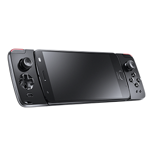
In 2016 MotoMods and Indiegogo launched "Transform the SmartPhone 2016" contest, in which Motorola and Indiegogo helped you to create a custom, snap on, add on for the Motorola Z family of phones.
Current Mods include Amazon Alexa Speaker set, a Projector, a high end camera, Sound Boost speaker set, wireless charging or just a supersized battery pack.

Build The Unexpected
Can you create a moto mod that helps people discover new ways to connect, work and entertain?
Last year, we reimagined what a smartphone can do with moto mods that snap on to turn the moto z into a super-zoom camera, boombox, projector—you name it. The Keyboard Mod was among those invented and this year, we’re bringing it to stores. Now it’s your turn to get in front of millions of Indiegogo backers, showcase your product at Motorola HQ in Chicago and boost your business.
If you want to enter "Transform the Smartphone 2018", modify your Moto Z or develop a product to take to market, we stock the Development kit, Adapter Board and even perf' board... for your mobile phone. Living in the future sure is crazy!
 |  |  |
| Moto Mods Development Kit (MDK) | Moto Mods Perforated Board | Moto Mods HAT Adapter Board |
Moto Mods MDKMoto Mods MDK | Moto Mods Perf BoardMoto Mods Perf Board | Moto Mods Hat AdapterMoto Mods Hat Adapter |
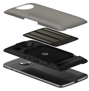
| The Moto Mods Development Kit (MDK) abstracts complex areas of the Moto Mod architecture so you can focus on your design, create a prototype and refine your concepts quickly and efficiently. | The Perforated Board is the primary vehicle for developing of your MDK Project (included with the MDK). This is a blank slate for soldering your own components in place. | The HAT Adapter Board is Raspberry Pi HAT compatible and allows the use of commercially available HATs. It includes the 40-pin header, camera, and display connectors. |
| Submit your Idea | Develop A Prototype | Crowdfund Your Moto Mod |
|---|---|---|
Share your moto mod idea and your plan to develop it in the submission form. |
Start developing a prototype for your moto mod idea. A selected few will receive a free moto mods development kit and a moto z phone (a $1,000 value). |
Launch a crowdfunding campaign to fund your moto mod development with Indiegogo's support. |
https://enterprise.indiegogo.com/motomod/
Grand Prize WinnersUp to 10 winners will win a trip to Chicago and pitch to the Motorola executive development team. |
FinalistsUp to 50 finalists will receive a moto z and an MDK to prototype and crowdfund their concepts. |
| Now | Submit Idea and Launch Crowdfunding Campaign Submit your project by February 6. Tell us all about your moto mod idea and your development plan! |
| 6th February 2018 | Last Day to Submit an Idea. This is the last day to submit an idea for a moto z and MDK |
| 1st April 2018 | Last Day to Launch a Indigogo Crowd Funding Launch your campaign by this date to qualify for the Grand Prize. |
| 13th April 2018 | Judges Review Campaigns The judges will deliberate and determine who will win the Grand Prizes. |
| 23rd April 2018 | Winners Announced Winners are announced at Motorola's headquarters and get invited into the Motorola Accelerator Program. |

Perforated Board
At a glance the perforated board seems like a nice expansion board. It looks like you can solder your projects directly to the board, plug it into the back of your phone, and away you go with a new custom feature you added to your phone. From the look of the board, most developers would say “oh that looks convenient to get my own custom electronics interacting with an app on my phone.” But, they’re completely wrong.
The board has 26 rows of 10 columns of through holes to solder to. Judging by that lengthy connector on the bottom, one would imaging they can directly connect the electronics that are soldered to the through holes and rails on the sides which would be electrically connected to the 80-pin connector. It must be that some of those 80-pins are GPIO tied to the grid of through holes or the grid of 260 holes has been multiplexed back to the 80-pin connector.
Motorola states on their website, “The Perforated Board is the primary vehicle for starting development of your Moto Mods Development Kit project. It brings the 80-pin connector to an accessible surface.“ I have found that this is simply not the case.
Not one of those holes is connected to anything except to the rows of 5 holes and the rails. There is no electrical connection from the through holes inside the board back to the connector. Motorola has given you a perfboard with an isolated connector on it.
The only thing that does connect back to the Reference Mod are test points above and below the connector’s exposed pads. So, if you want to use this board to actually interact with you custom electronics when you plug in this card, you have to solder wires from the test points to the rails and through holes. This is not the ideal way to prototype as Motorola has provided you. Was this board intended to be a card to mechanically hold your electronics to the board? Or do they actually expect people to solder leads from test points below to the through holes to get power and DIO lines to the perfboard?
Sure, you could have an external power supply to the rails but you still have to solder leads from test points, and having an external power supply defeats the purpose of this whole modular phone idea anyway.
They easily could've at least taken out the last couple rows and replaced it with through holes that have internal board traces back to the 80-pin connector.


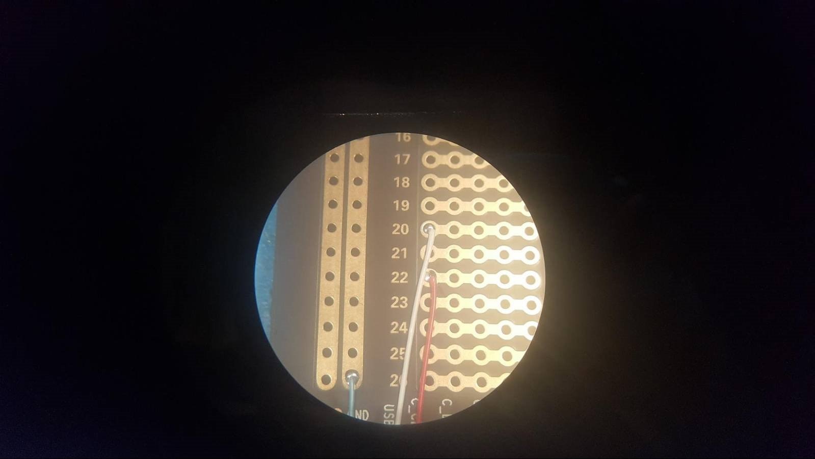
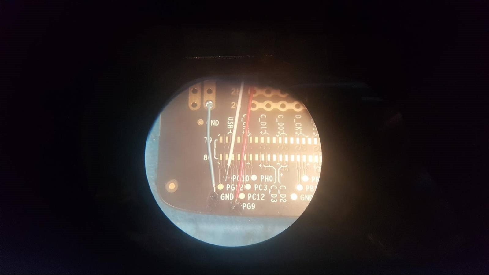
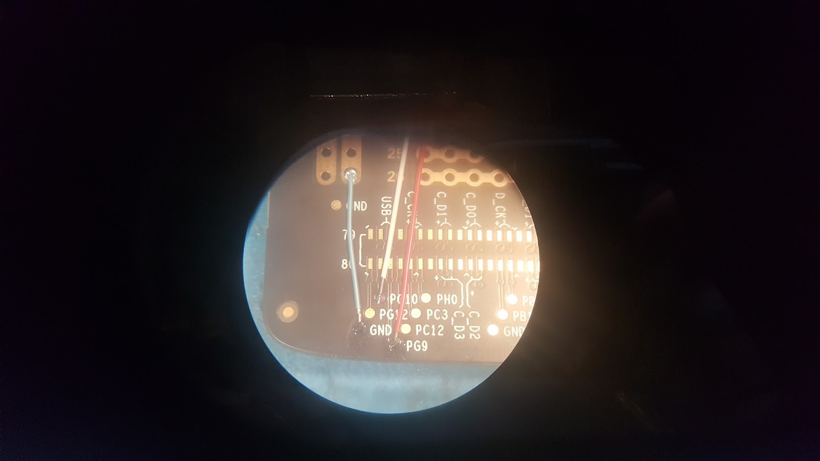
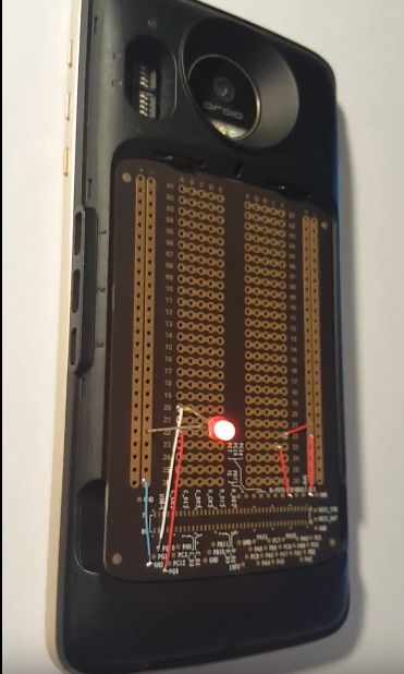
To get an external LED to blink you have to solder jumper wires across the surface. The white wire is soldered to the test point “PG10” and the blue wire is soldered from the GND test point to the “-” rail. All other soldered wires were for experiment and unused for this project. The bottom right side red wires bring up the 1.8V and 3.3V test points for power. There is also a 5V test point, shown below as unsoldered “5P0”
Also, I chose the smallest through-hole LED I had, 3mm diameter. When soldered to the board, I could not get the back cover on over the LED. All-in-all, not a lot of considerations were put into this design.
However, I did in fact get it to work. I blinked an LED. It does work fairly well. It just isn't as turnkey and user-friendly as I would have wanted.
Have a story tip? Message me at: cabe(at)element14(dot)com
I have a Moto-Z and need to include the LAN9500A driver in the linux kernel since my USB device uses that chip. Is there instructions on how to build a Android ROM for the Moto-Z that would include this driver?
Thx,
Y-
Index of the Moto Mods Developer project:
Moto Mods Developer Part 1 - Getting Started - Virtual Machine Setup and Linux Install
Moto Mods Developer Part 2 - Getting Started - SDK Setup & Android Studio Install
Moto Mods Developer Part 3 - Firmware Setup
Moto Mods Developer Part 4 - Getting Started - Make Build-Folder, add Utility and OS files
Moto Mods Developer Part 5 - Flashing Firmware with MDK Utility
Moto Mods Developer Part 6 - Blinking an LED on the Moto Mods Perfboard
Moto Mods Developer Part 7 - Modifying the C file for the perfboard LED
Moto Mods Developer Part 8 - Configure Nuttx
Moto Mods Developer Part 9 - Updating the Hardware Manifests file
Moto Mods Developer Part 10 - Cont’d Configure and Compile Nuttx
Moto Mods Developer Part 11 - Load newly created Nuttx Firmware onto Reference Board
Moto Mods Developer Part 12 - Soldering the Test Points to use the perfboard
Moto Mods Developer Part 13 - Making custom App to control the Firmware
| {gallery} Making custom App to control the Firmware |
|---|
I modified the MDK-Utility app for my own use by deleting unnecessary parts of the app that I didn’t need for my blinker app. The Information panel and switcher “cards” were kept. Other cards were deleted. |
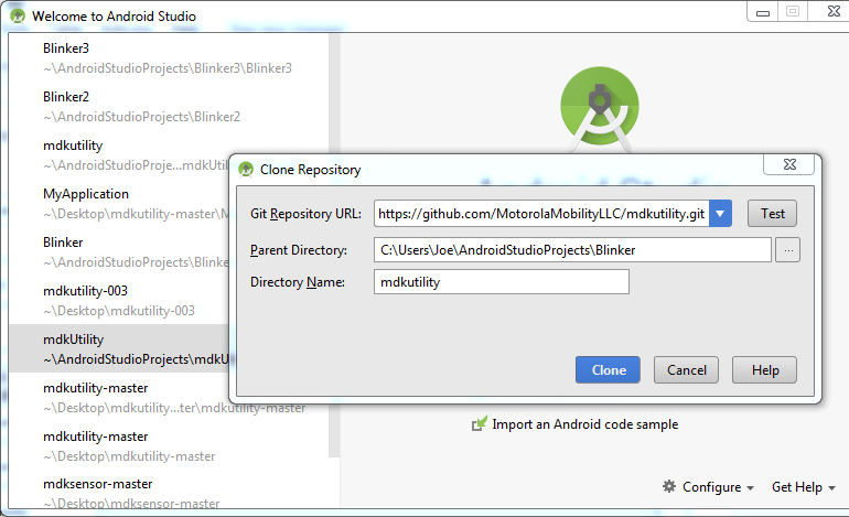
To get started with modifying this app, I needed to clone the MDK-Utility app repository to Android Studio. |
Graphic View layout |
Code View Layout |
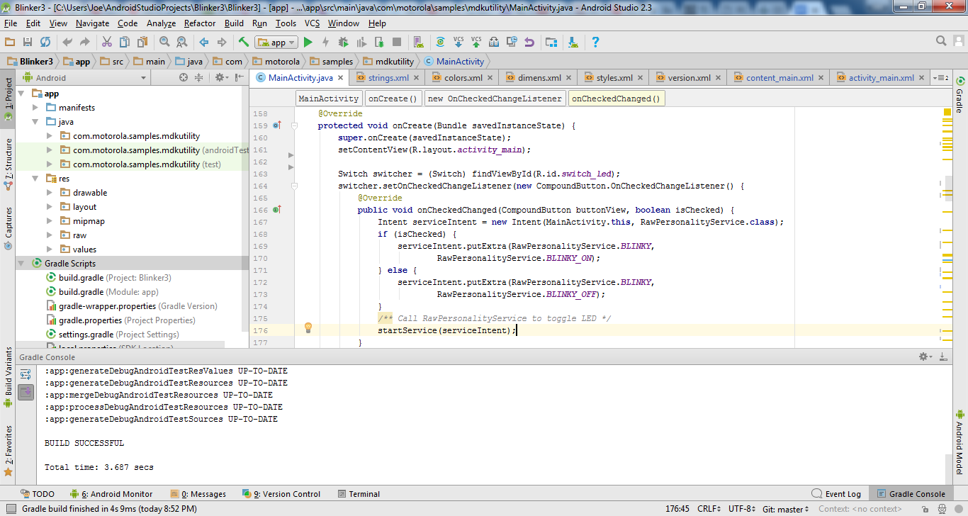
In MainActivity, the code for Switcher, the “switch_led” id corresponds to the id of the graphical switch on the app panel. When the switch is activated, it runs the raw personality service called blinky using the raw protocol to send the blink boolean to the reference moto mod, where the STM32 micro receives it and runs the blinky routine on its firmware. |
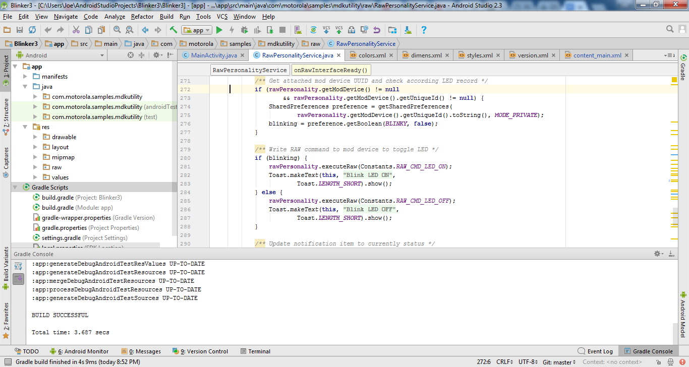
Raw Personality Service: |
Below is my custom Blinker App using parts of the MDK Utility and CardView layout.  |
What it should look like! |
The Slideshow above is also below:
An app can be made in any Android Studio platform including Windows, Linux or Mac. For this I used Windows.
The MDK-Utility app that motorola provides for loading firmware uses Android CardView for the layout look. Where each “card” is a different section with a display and/or button. As Shown below:
I modified the MDK-Utility app for my own use by deleting unnecessary parts of the app that I didn’t need for my blinker app. The Information panel and switcher “cards” were kept. Other cards were deleted.
To get started with modifying this app, I needed to clone the MDK-Utility app repository to Android Studio.
Graphic View layout
Code View Layout
In MainActivity, the code for Switcher, the “switch_led” id corresponds to the id of the graphical switch on the app panel. When the switch is activated, it runs the raw personality service called blinky using the raw protocol to send the blink boolean to the reference moto mod, where the STM32 micro receives it and runs the blinky routine on its firmware.
Raw Personality Service:
Below is my custom Blinker App using parts of the MDK Utility and CardView layout
Index of the Moto Mods Developer project:
Moto Mods Developer Part 1 - Getting Started - Virtual Machine Setup and Linux Install
Moto Mods Developer Part 2 - Getting Started - SDK Setup & Android Studio Install
Moto Mods Developer Part 3 - Firmware Setup
Moto Mods Developer Part 4 - Getting Started - Make Build-Folder, add Utility and OS files
Moto Mods Developer Part 5 - Flashing Firmware with MDK Utility
Moto Mods Developer Part 6 - Blinking an LED on the Moto Mods Perfboard
Moto Mods Developer Part 7 - Modifying the C file for the perfboard LED
Moto Mods Developer Part 8 - Configure Nuttx
Moto Mods Developer Part 9 - Updating the Hardware Manifests file
Moto Mods Developer Part 10 - Cont’d Configure and Compile Nuttx
Moto Mods Developer Part 11 - Load newly created Nuttx Firmware onto Reference Board
Moto Mods Developer Part 12 - Soldering the Test Points to use the perfboard
Moto Mods Developer Part 13 - Making custom App to control the Firmware
| {gallery} My Gallery Title |
|---|
|
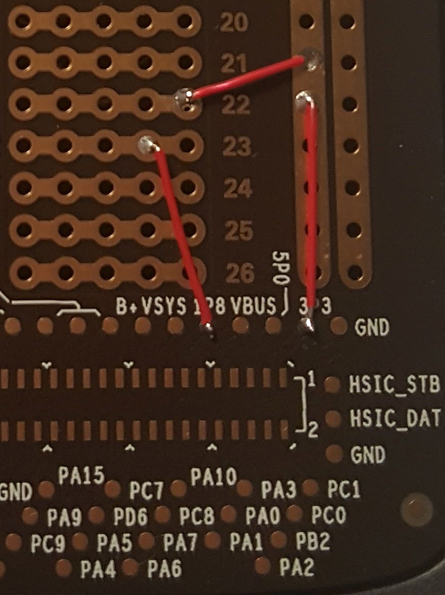
The power Test Points, located on the right have a 3.3V pad, 1.8V pad, and a 5V pad to use with GND. This side I pulled them up in case I wanted to power anything. |
3.3V is powering the rail and row 22. Row 23 is connected to the 1.8V pad. |
|
Slideshow above is also below:
Soldering the Test Points to use the perfboard
Shown below is the Moto Mods Reference Mod with a perfboard attached. One thing misconceiving about the perfboard is the grid of through holes. At first glance, it looks as though there is a way to access these through holes like a GPIO connected to the micro, to make it easy…. It is actually nothing but a breadboard. Nothing is connected to it going back to the phone nor the personality card connector. The only thing that does connect to this, are the test points at the bottom. The breadboard of course a perfboard with 2 columns of 26 rows of 5, the 5 are holes horizontally are connected. Then 2 + and - Rails, connected. The only internal traces on the board are from the connector to the Test Points. This doesn’t make it convenient to connect your phone to it, to actually use it.
This seems like they want you to use your own external power supply. The reference Moto Mod has a battery so why wouldn't you want to use it to prototype? One way to utilize the perfboard is to solder tiny jacketed (So as not to touch other TPs) wires to the board to bring power/ground up to the rails and I/O to the grid of through holes. Soldering to Test Points aren’t ideal because you don’t have a lot of mechanical strength for the solder joint, also it's harder to do. Luckily I had a microscope.
The ground pad is located on the left and right sides of the connector. The power pads are located on the right. I brought up the GND to the - rail on the left because the GP10 pad was located on the left and is phone GPIO addressable. So I brought that pad up to row 20 with the white wire as shown. The LED was soldered positive side Row 20 to GND on the - rail.
The power Test Points, located on the right have a 3.3V pad, 1.8V pad, and a 5V pad to use with GND. This side I pulled them up in case I wanted to power anything. 3.3V is powering the rail and row 22. Row 23 is connected to the 1.8V pad.
Index of the Moto Mods Developer project:
Moto Mods Developer Part 1 - Getting Started - Virtual Machine Setup and Linux Install
Moto Mods Developer Part 2 - Getting Started - SDK Setup & Android Studio Install
Moto Mods Developer Part 3 - Firmware Setup
Moto Mods Developer Part 4 - Getting Started - Make Build-Folder, add Utility and OS files
Moto Mods Developer Part 5 - Flashing Firmware with MDK Utility
Moto Mods Developer Part 6 - Blinking an LED on the Moto Mods Perfboard
Moto Mods Developer Part 7 - Modifying the C file for the perfboard LED
Moto Mods Developer Part 8 - Configure Nuttx
Moto Mods Developer Part 9 - Updating the Hardware Manifests file
Moto Mods Developer Part 10 - Cont’d Configure and Compile Nuttx
Moto Mods Developer Part 11 - Load newly created Nuttx Firmware onto Reference Board
Moto Mods Developer Part 12 - Soldering the Test Points to use the perfboard
Moto Mods Developer Part 13 - Making custom App to control the Firmware
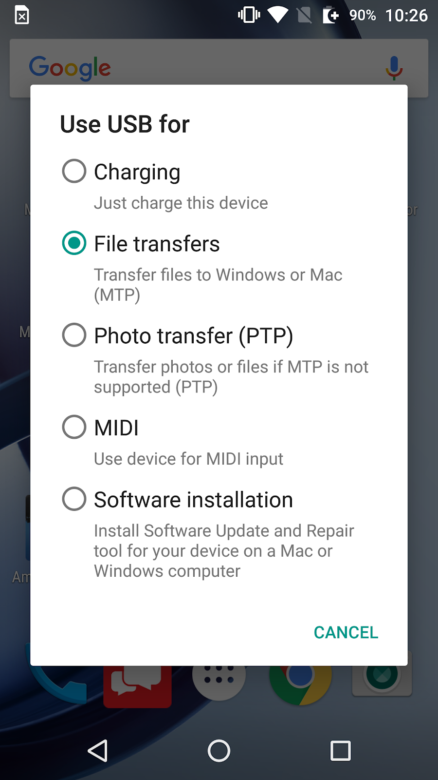
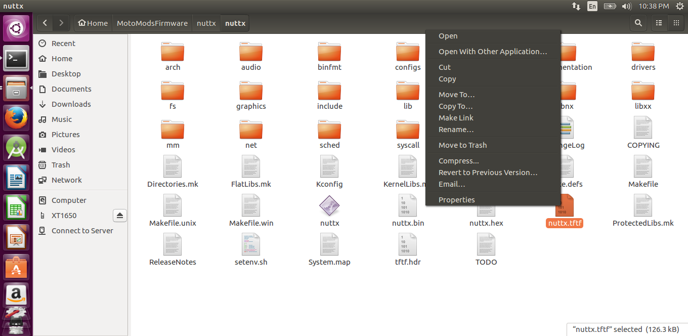
With your Moto Z Droid plugged in and on file transfer mode, Navigate to the second nuttx folder, right click and ‘Copy To…’
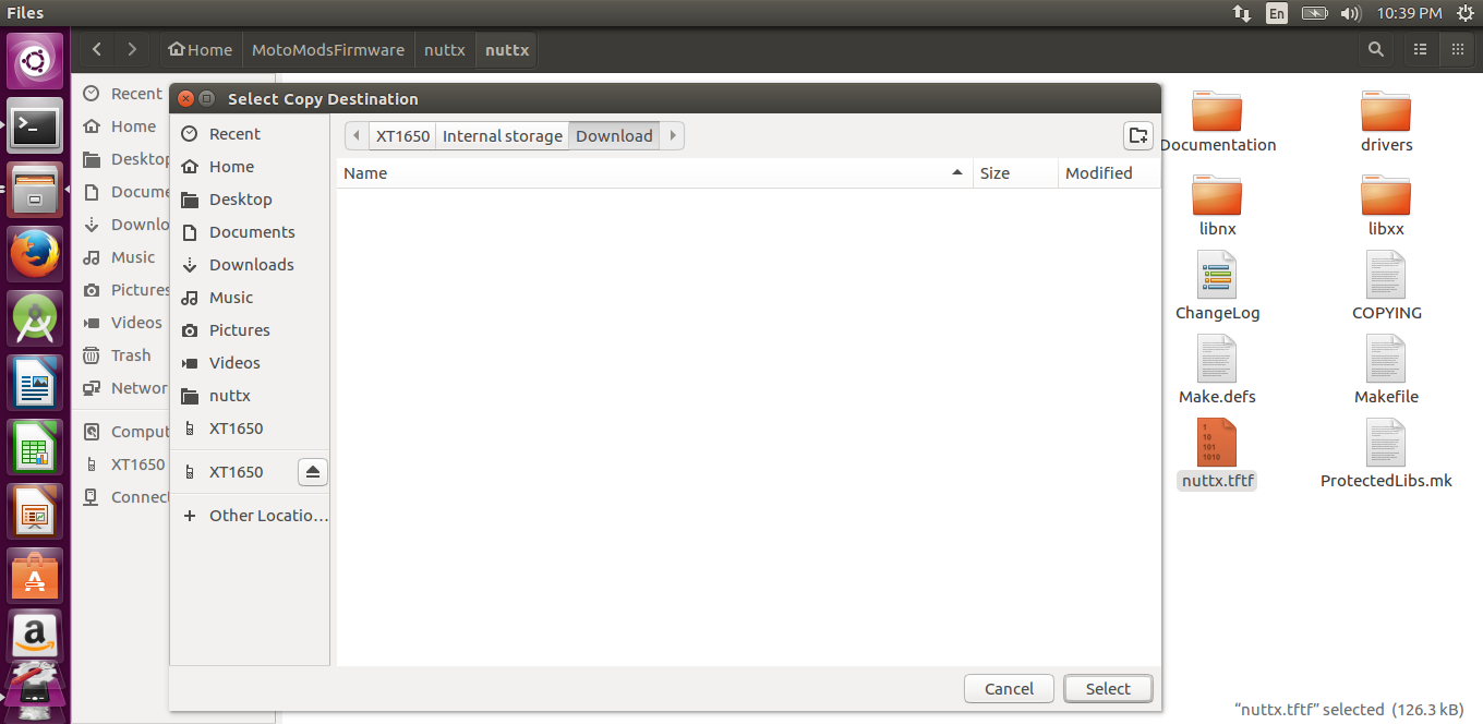
Select phone name and save it in the Phone’s Downloads folder
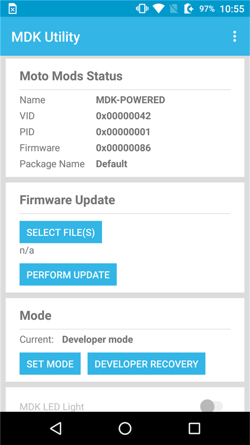
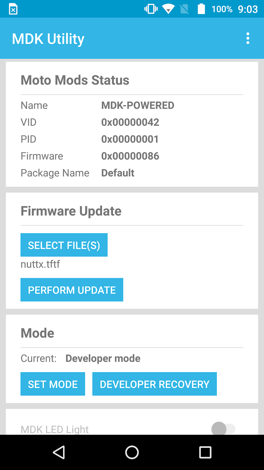
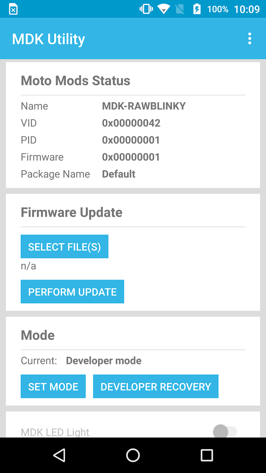
On the phone, launch MDK Utility app.
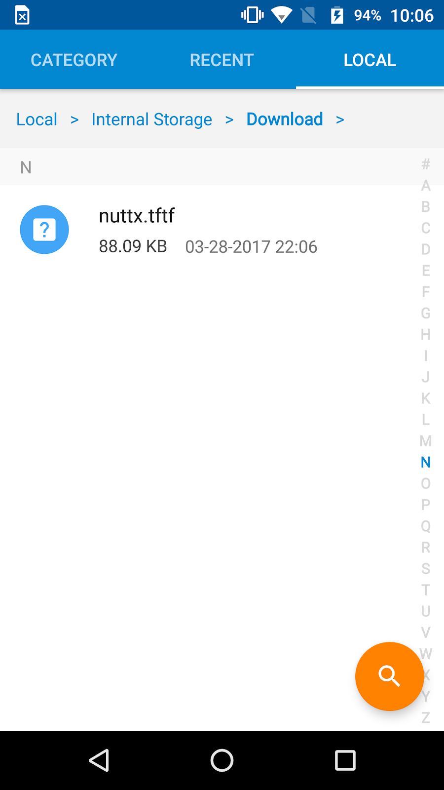
In Developer Mode, Select files→ nuttx.tftf
Hit “PERFORM UPDATE”
If prompted, click continue.
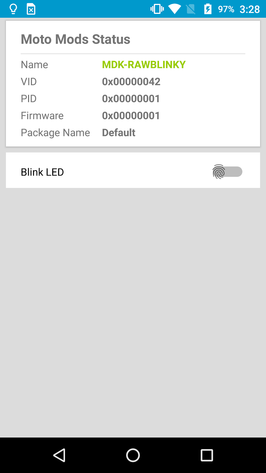
The firmware name will show “MDK-RAWBLINKY” as we named in the Hardware Manifests file.
NOTE: For some reason the MDK Utility app from the app store doesn’t let you switch back to “SET MODE” once your custom firmware is loaded. The only way to use the “MDK LED Light” switch in the app is to be in SET MODE. The switch is always greyed out in DEVELOPER MODE.
The way around this: On github, in the MotorolaMobilityLLC repository, there is an mdkutility which is a different version that does not have modes in its APK. Download and install this APK. Load the “MDK-RAWBLINKY” firmware with the app store version of MDK Utility. Then switch to the repository APK. This will allow you to use the “MDK LED Light” switch with your custom firmware. Now the firmware should blink the LED soldered to the test point PG10. Turning the switch ON will start the blinking.
There you go….success. Custom blinky firmware using Moto Mods with perfboard.
Index of the Moto Mods Developer project:
Moto Mods Developer Part 1 - Getting Started - Virtual Machine Setup and Linux Install
Moto Mods Developer Part 2 - Getting Started - SDK Setup & Android Studio Install
Moto Mods Developer Part 3 - Firmware Setup
Moto Mods Developer Part 4 - Getting Started - Make Build-Folder, add Utility and OS files
Moto Mods Developer Part 5 - Flashing Firmware with MDK Utility
Moto Mods Developer Part 6 - Blinking an LED on the Moto Mods Perfboard
Moto Mods Developer Part 7 - Modifying the C file for the perfboard LED
Moto Mods Developer Part 8 - Configure Nuttx
Moto Mods Developer Part 9 - Updating the Hardware Manifests file
Moto Mods Developer Part 10 - Cont’d Configure and Compile Nuttx
Moto Mods Developer Part 11 - Load newly created Nuttx Firmware onto Reference Board
Moto Mods Developer Part 12 - Soldering the Test Points to use the perfboard
Moto Mods Developer Part 13 - Making custom App to control the Firmware
| {gallery:autoplay=false} MotoMods Developer Part 10 |
|---|
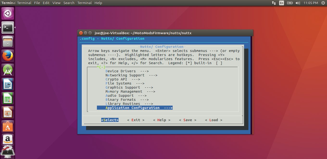
Step 1:Now that we’ve edited the Hardware Manifest file we need to go back and configure it back in menuconfig |
Step 2:Scroll down on main menu |
Step 2: |
Step 2: |
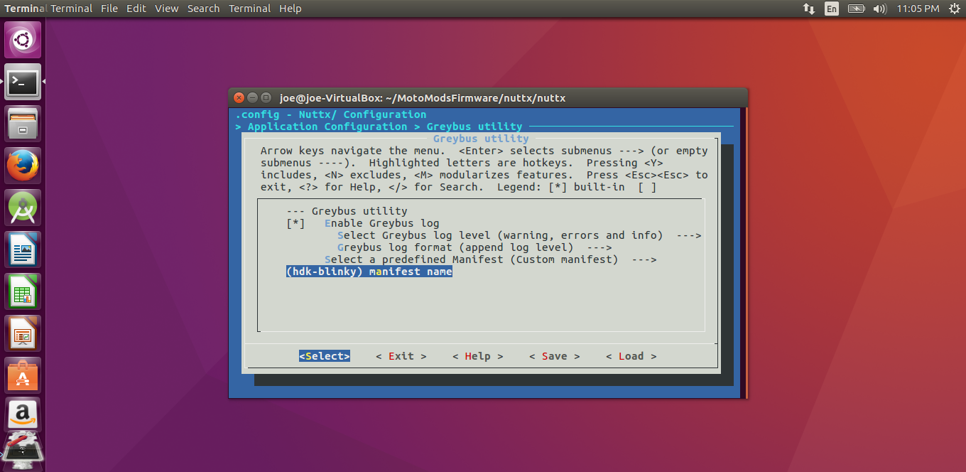
Step 3: Click on the last field, we will name this field the same name as the Hardware Manifests file “hdk-blinky.mnfs” |
R
Step 4: Exit 3X. |
Step 5: Configure the Bootloader |
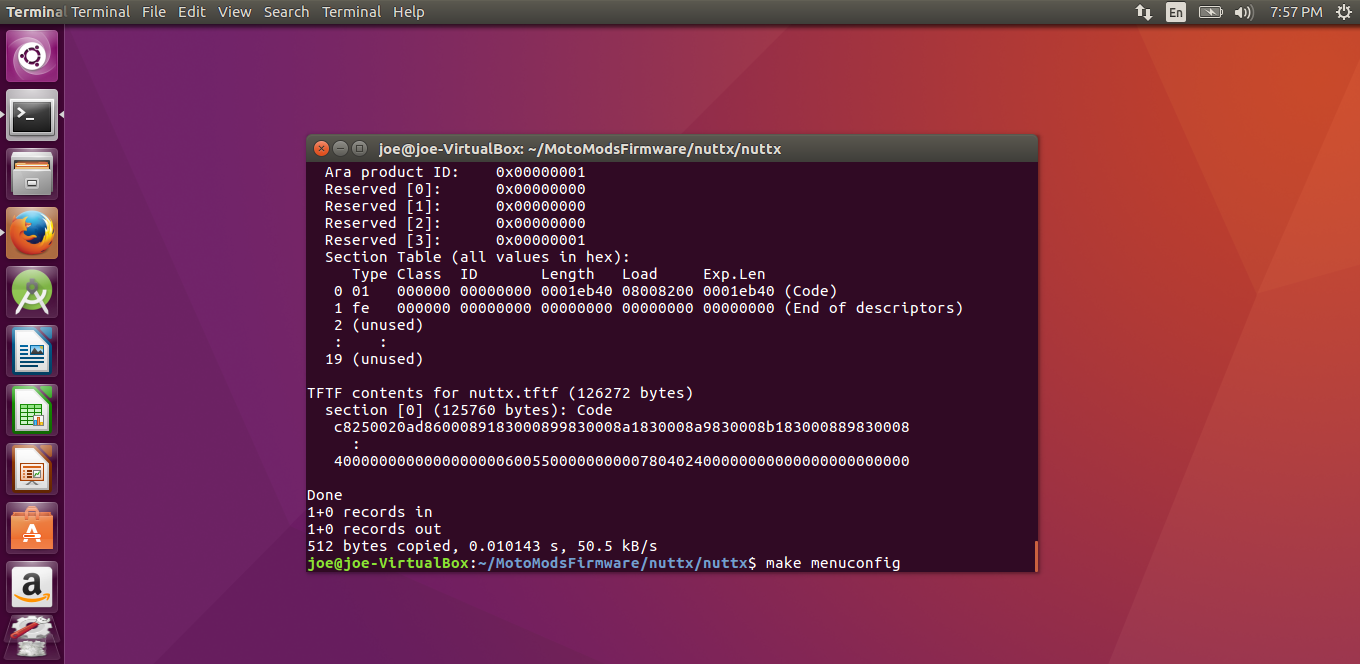
Step 6: Compile Nuttx |
Step 6: |
The above gallery is also the pictures and text below:
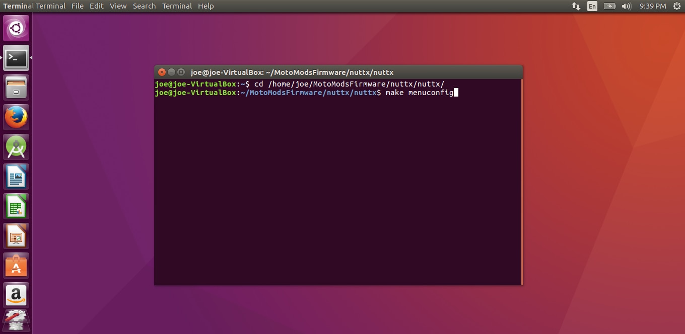
Now that we’ve edited the Hardware Manifest file we need to go back and configure it back in menuconfig

$ cd $BUILD_TOP/nuttx/nuttx
$ make menuconfig
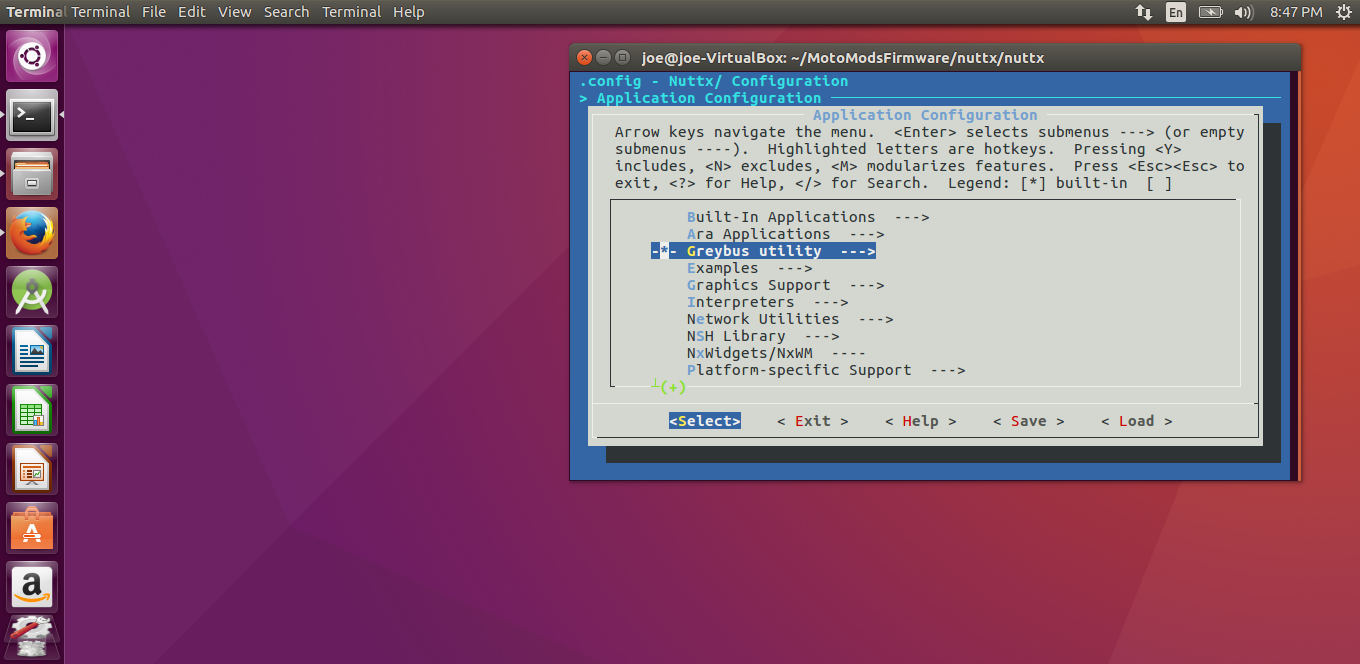
Application Configuration --->
-*- Greybus utility --->
Select a predefined Manifest (Custom manifest)
(hdk-blinky) manifest name
Scroll down on main menu
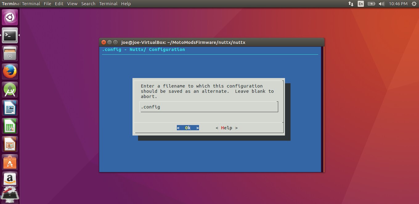
Click on the last field, we will name this field the same name as the Hardware Manifests file “hdk-blinky.mnfs”
Enter “hdk-blinky”
Hit Ok and scroll right and press Save.
Exit 3X.
Configure the Bootloader

Compile Nuttx
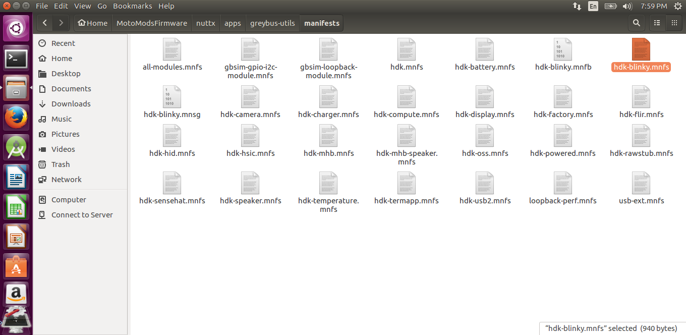
Before we compile Nuttx, we need to change the hardware manifest file. The .mnfs file for Blinky is located in
./nuttx/apps/greybus-utils/manifests as created above.
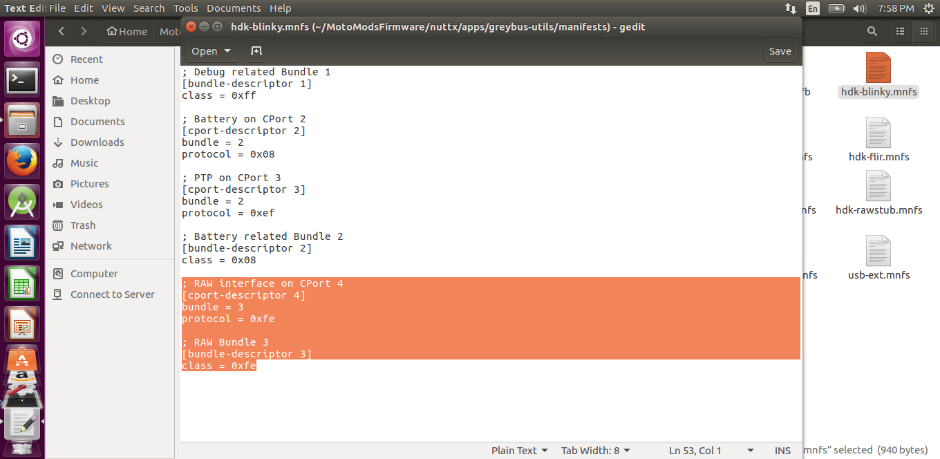
Add the following lines to the end of the document:
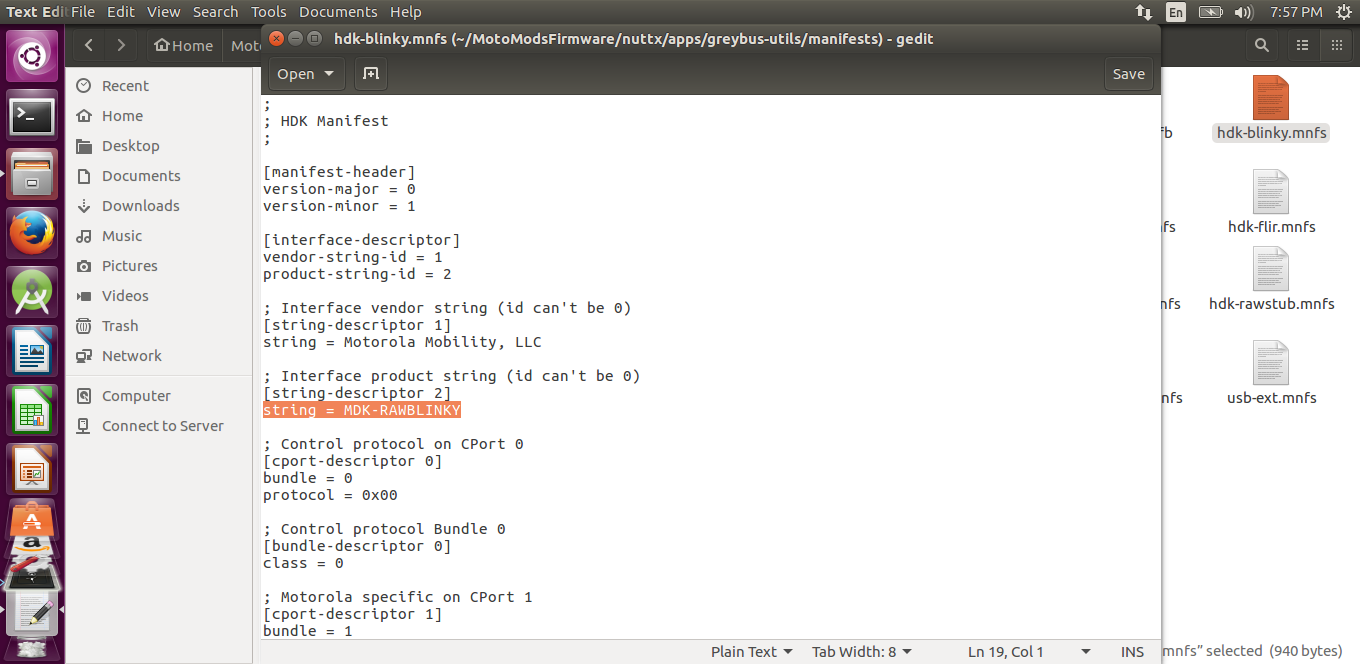
At the top of the file we can input a string that will show on the app when the firmware is loaded. In [string-descriptor 2], I named my firmware “MDK-RAWBLINKY”
Cabe