Index of the Moto Mods Developer project:
Moto Mods Developer Part 1 - Getting Started - Virtual Machine Setup and Linux Install
Moto Mods Developer Part 2 - Getting Started - SDK Setup & Android Studio Install
Moto Mods Developer Part 3 - Firmware Setup
Moto Mods Developer Part 4 - Getting Started - Make Build-Folder, add Utility and OS files
Moto Mods Developer Part 5 - Flashing Firmware with MDK Utility
Moto Mods Developer Part 6 - Blinking an LED on the Moto Mods Perfboard
Moto Mods Developer Part 7 - Modifying the C file for the perfboard LED
Moto Mods Developer Part 8 - Configure Nuttx
Moto Mods Developer Part 9 - Updating the Hardware Manifests file
Moto Mods Developer Part 10 - Cont’d Configure and Compile Nuttx
Moto Mods Developer Part 11 - Load newly created Nuttx Firmware onto Reference Board
Moto Mods Developer Part 12 - Soldering the Test Points to use the perfboard
Moto Mods Developer Part 13 - Making custom App to control the Firmware
| {gallery} My Gallery Title |
|---|
|
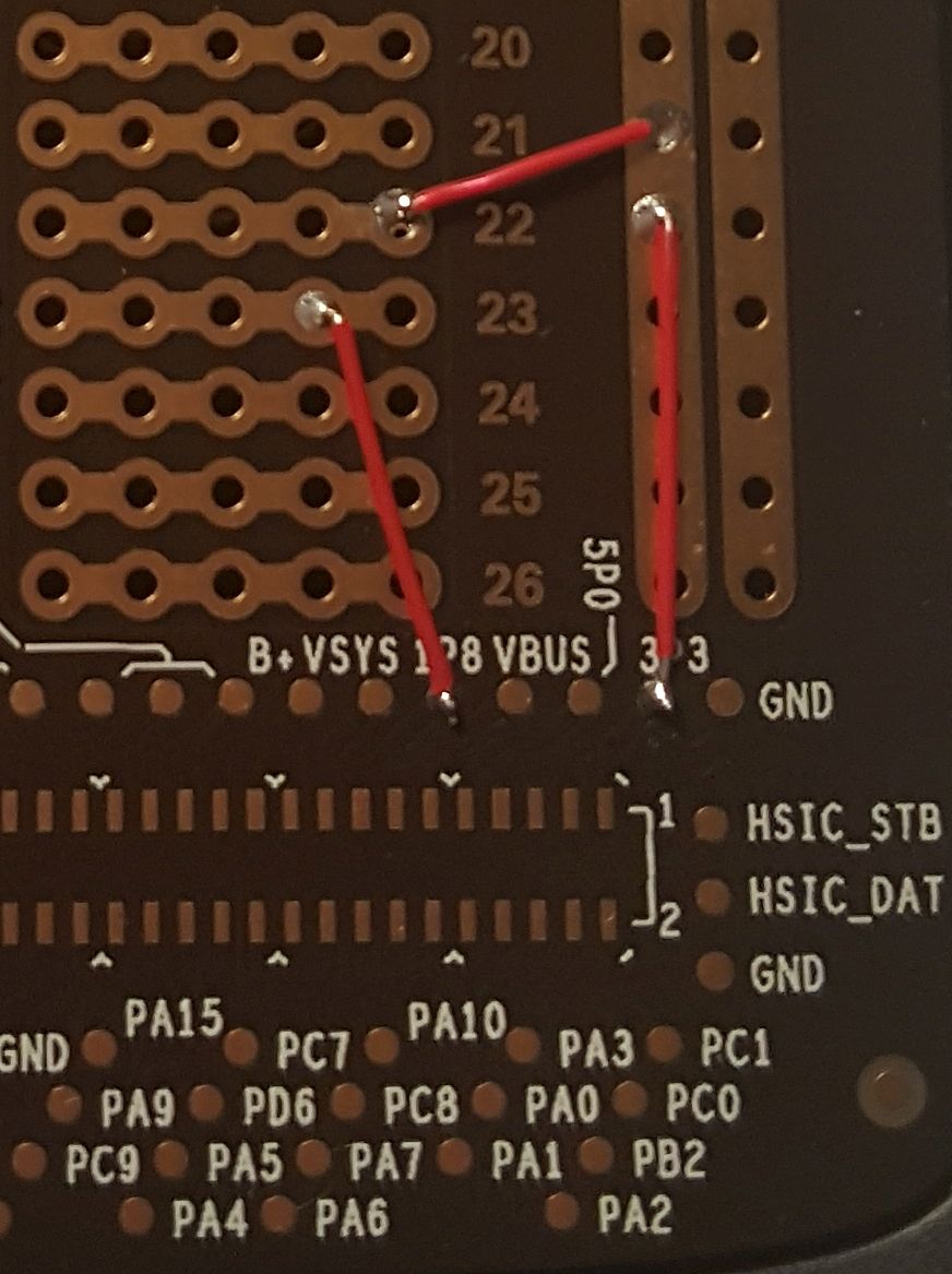
The power Test Points, located on the right have a 3.3V pad, 1.8V pad, and a 5V pad to use with GND. This side I pulled them up in case I wanted to power anything. |
3.3V is powering the rail and row 22. Row 23 is connected to the 1.8V pad. |
|


Slideshow above is also below:
Soldering the Test Points to use the perfboard
Shown below is the Moto Mods Reference Mod with a perfboard attached. One thing misconceiving about the perfboard is the grid of through holes. At first glance, it looks as though there is a way to access these through holes like a GPIO connected to the micro, to make it easy…. It is actually nothing but a breadboard. Nothing is connected to it going back to the phone nor the personality card connector. The only thing that does connect to this, are the test points at the bottom. The breadboard of course a perfboard with 2 columns of 26 rows of 5, the 5 are holes horizontally are connected. Then 2 + and - Rails, connected. The only internal traces on the board are from the connector to the Test Points. This doesn’t make it convenient to connect your phone to it, to actually use it.
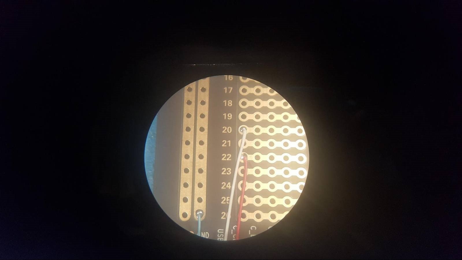
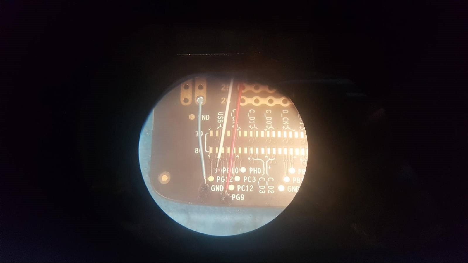
This seems like they want you to use your own external power supply. The reference Moto Mod has a battery so why wouldn't you want to use it to prototype? One way to utilize the perfboard is to solder tiny jacketed (So as not to touch other TPs) wires to the board to bring power/ground up to the rails and I/O to the grid of through holes. Soldering to Test Points aren’t ideal because you don’t have a lot of mechanical strength for the solder joint, also it's harder to do. Luckily I had a microscope.

The ground pad is located on the left and right sides of the connector. The power pads are located on the right. I brought up the GND to the - rail on the left because the GP10 pad was located on the left and is phone GPIO addressable. So I brought that pad up to row 20 with the white wire as shown. The LED was soldered positive side Row 20 to GND on the - rail.

The power Test Points, located on the right have a 3.3V pad, 1.8V pad, and a 5V pad to use with GND. This side I pulled them up in case I wanted to power anything. 3.3V is powering the rail and row 22. Row 23 is connected to the 1.8V pad.