


I welcome you to the second part of tutorial. In this tutorial I show two things. In first part, I shown how to develop application for nRF52840 MCU presented on Arduino Nano 33 BLE Sense without Arduino IDE. In this second part I will show how to debug this app in IDE (running on your Windows/Linux computer) using Raspberry Pi as a replacement for expensive JTAG/SWD probe. I will show how to flash MCU connected over SWD to Raspberry Pi GPIOs. Tutorial is separated to two parts. In first part I shown how to develop application and in second part I show how to debug it. This tutorial is part of my RoadTest review about Arduino Nano 33 BLE Sense. All my opinions about this Arduino, sensors, MCU, documentation and software are presented in chapters with “Review” at the beginning of name. This tutorial is based on my experiences gained when roadtesting this Arduino. Following Table of Contents contains links to all chapters of my review.
Table of Contents
- Introduction
- Review of Development Board
- Review of Onboard Sensors
- Review of Microcontroller and BLE Module
- Review of Software
- Review of Documentation
- Tutorial 01: Accessing Sensor Values
- Tutorial 02: nRF52840 Application without Arduino IDE
- Part 2 - Debugging nRF52840 Using Raspberry Pi (this article)
Tutorial 02 – Part 2 – Debugging nRF52840 Using Raspberry Pi
In this part of tutorial I will show how to connect Arduino to Raspberry Pi and how-to setup microcontroller debugging without need to own expensive SWD/JTAG debugger probe like Segger J-Link. In this tutorial I will use Raspberry Pi instead of this probe.
Disclaimer: For following this tutorial, you will need to physically modify your device by soldering. I will also overwrite default Arduino bootloader which is used for programming board from Arduino environment. If you will follow this tutorial, you will not be able to program Arduino from Arduino IDE anymore. While I will show how to backup (and restore) Arduino bootloader in tutorial, you still must take special care of this and think multiple times before doing anything. Author of this tutorial is not responsible for any damage caused by following this tutorial to your device. Remember that you do it on your own risk.
Theory
Normally when you develop using Arduino IDE and click Run button in Arduino IDE, the Arduino IDE will open communication over virtual serial port which is provided over USB bus by firmware in microcontroller. Part of firmware responsible for this upload is named as bootloader. Programming using this approach is visualised on following diagram.

This approach has big advantage that it is very simple to understand but have also some disadvantages. This approach is very slow and also has very limited options to allow you debug your program. Debugging is efficiently limited to terminal prints, visualization states using LEDs and so on.
Almost every ARM Cortex-M MCU has debug interface which can be used for stopping processor core on specified instruction and monitoring internal resource of MCU when core is stopped. This approach is available over SWD or JTAG bus. Because these interfaces are not supported by computers you need some convertor which can translate commands from PC to SWD/JTAG signals. Usually this is some debug probes like Segger J-Link, Keil ULINK, Daplink, ST-Link or many others. Structure of this approach can look as follow.

This method have multiple advantages like speed of upload (up to megabits per second in comparison with kilobits per seconds in case of serial) and full debug support, but it have one big disadvantage – you need a debug probe like J-Link. Many professional probes are very expensive but there are ways how to convert some thing or other board to debug probe. For example, If you own some Nucleo or Discovery board from ST you can use it as debug probe. It will looks as follow.

And in real world it will look like on following picture. You can see STM Discovery board (green board with display) with SWD wires connected to roadtested Arduino. SWD is composed by two wires (black and white on picture). One of them is CLK (SWCLK) and second is for data (SWDIO). Green wire is common ground and yellow wire is reset signal to make option to reset MCU by debug probe.

But you still need to have some very uncommon board for debugging. Another very interesting option is to replace debug probe (ST-Link on STM Discovery board in previous example) by Raspberry Pi. Yes, you can use Raspberry Pi for programming and debugging different chip. Raspberry Pi have GPIOs which can be used for emulating SWD bus. Connection is very similar to previous one and I will describe it more later.

The diagram in this case will looks as follows.

Of course, you can eliminate PC from the diagram because Raspberry Pi is also PC.

Exposing SWD Wires on Arduino Nano 33 BLE Sense
Now we must resolve black and white wires. As you can see, they are connected to the bottom of board. It is because SWD interface is not exposed on expansion header of board, but it is accessible only on test points at the bottom side of board. There are 5 test points. There are GND and 3.3V pin which we do not need to solder because they are easily accessible on expansion header. There are also reset signal which is also accessible on expansion header. And finally, there are two SWD wires which we must expose. If you want, you can solder all 5 wires but these 2 are sufficient.

Setup OpenOCD on Raspberry Pi
Now we need to setup software on Raspberry Pi which will open debugging server with interface for debugging Arduino. Software for doing this is named OpenOCD. You can find them in repositories but I recommend installing latest (or latest stable) version from git instead. I will show up commands how to setup this on fresh installation of Raspbian.
As first we need to install some dependencies and tools for building OpenOCD.
sudo apt update
sudo apt install libtool autoconf automake texinfo telnet gdb-multiarch
Now we can clone OpenOCD from git repository (official mirror).
git clone git://repo.or.cz/openocd.git
cd openocd/
And now, we can configure compilation, build it, and install built binaries to system. Compilation will take some time. It may take more than 10 minutes.
./bootstrap
./configure --enable-bcm2835gpio
make -j4
sudo make install
I will modify default pinout for easier interconnection Arduino with Raspberry Pi. OpenOCD needs two configuration files. One for defining debug probe (Raspberry Pi in our case) and target MCU (nRF52840 in our case). I will copy script for defining debug probe to my home and edit them in a way that I change swdio and swclk pins to GPIO2 and GPIO3 on raspberry pi, and I enable support for restart MCU by GPIO4. You can use your favourite editor instead of vim.
cp tcl/interface/raspberrypi2-native.cfg ~/rpi_as_debugger.cfg
cd
vim ~/rpi_as_debugger.cfg
I marked changes by red lines on following screenshot.

Now you can interconnect your Arduino Nano 33 BLE Sense with Raspberry Pi. Connect GND on Arduino (green wire in my case) with GND on Raspberry Pi. Then connect SWCLK wire (white wire in my case) to GPIO2 on Raspberry Pi. Connect SWDIO (black wire in my case) to GPIO3 on Raspberry Pi. And finally connect RESET (yellow wire in my case) from Arduino expansion header to GPIO4 on Raspberry Pi.
Now you can start OpenOCD command to check if it works. OpenOCD have multiple parameters of two types. Parameter -f executes all commands from file. We will use this command to load configuration for debug probe (rpi_as_debugger.cfg) and for target which is stored in openocd/tcl/target folder. The same configuration is also stored somewhere in /usr/share. OpenOCD can search common directories for these configs so we can specify just target/nrf52.cfg. Second type of parameters are -c which executes command. Commands and files loaded from command line are executed from left to right. So as first we will load configuration script for debug probe. Second, we must specify that we are using SWD and not a JTAG using transport select command. Because my soldering skills are not good and I were receiving errors due to signal malformation on this very high-speed bus, I decreased SWD bus speed from default 1 MHz to 100 kHz using adapter speed 100 command. Finally we will include configuration for target MCU.
Full command line look as follows:
openocd -f rpi_as_debugger.cfg -c "transport select swd" -c "adapter speed 100" -f target/nrf52.cfg
You should see that nrf52 target with 6 breakpoints and 4 watchpoints was found. Every time you see number of HW breakpoints and watchpoint in OpenOCD, you can expect that it works. In output you can see that OpenOCD started multiple servers for you. Later we will use server which listen at port 3333 for connecting IDE to this debugger, but now we will use plain telnet connection to try running some additional commands.

Now open second terminal on Raspberry Pi and connect to telnet server.
telnet localhost 4444
Now we will stop CPU Core on Arduino for investigating what is running inside chip. If you were running for example blinky code on your Arduino it will stop blinking because CPU stops.
halt
You should receive message that your MCU core was halted and current state of some system registers like program counter (pc) which is pointer to the instruction which will be executed after you release CPU again.
Before we overwrite flash memory of MCU by some other program later, I recommend to backup current firmware which contains Arduino bootloader. When you flash your MCU by some non-Arduino generated firmware later, you completely lost USB connection and emulated serial port. You will not be able to reprogram Arduino from Arduino IDE anymore. When you decide to switch back to Arduino environment you must restore this backup firmware. Restore of backup is described later in this tutorial.
Backup Firmware
Run the following command in telnet window. This command creates arduino_nano_flash_backup.bin file with content of memory starting at address 0 (on some MCUs FLASH starts on different address than 0, but nRF52840 has FLASH mapped to address 0) and length 0x100000 bytes which is 1 MiB. This command loads full content of whole flash memory of MCU and dumps it into this file. Depending on how much you lowered speed of the bus, it will take some time. In my case it took about 70 seconds to dump whole flash but if you soldered SWD wires well and you do not decrease bus speed much, you can expect that it take about 10 seconds on 1 MHz. You should see message that command was completed.
dump_image arduino_nano_flash_backup.bin 0 0x100000
I recommend running this command multiple times to prevent error from signal disruption on SWD bus. I also recommend stopping OpenOCD and change clock frequency before additional attempts to backup flash content.
dump_image arduino_nano_flash_backup2.bin 0 0x100000
dump_image arduino_nano_flash_backup3.bin 0 0x100000
After dumping you can verify that all received files are the same using md5sum command
md5sum arduino_nano_flash_backup*
All 3 hashes should be the same.
Programming firmware into device
Now you need HelloUartWorld.elf file which you created in previous part of this tutorial. Copy them from computer to Raspberry Pi. You can use SCP for transferring file from your computer to Raspberry Pi. You must change IP address in following command to IP address of your Raspberry Pi.
scp "HelloUartWorld.elf" pi@192.168.0.53:/home/pi/HelloUartWorld.elf
Now you can flash firmware to MCU on Raspberry Pi. You can do that using OpenOCD with additional commands. We will execute multiple OpenOCD commands to do that. As first we will specify that we want to start TCP server allowing connection from any computer in local network. By default, it listens only from connections from localhost. We will need it later when we will be connecting IDE to debugging server provided by OpenOCD. Command is:
-c 'bindto 0.0.0.0'
Now we specify debug probe configuration file, switch from JTAG to SWD mode, decrease frequency of SWD bus and specify configuration for target MCU as we have done in previous section.
-f rpi_as_debugger.cfg
-c 'transport select swd'
-c 'adapter speed 250'
-f target/nrf52.cfg
Now we must execute command which switches OpenOCD from configuration to running mode. Then we halt core. Then we erase whole FLASH memory, then we program new firmware to device and then we reset device.
-c 'init'
-c 'halt'
-c 'nrf5 mass_erase'
-c 'program HelloUartWorld.elf verify'
-c 'reset'
Full command line is following:
openocd -c 'bindto 0.0.0.0' -f rpi_as_debugger.cfg -c 'transport select swd' -c 'adapter speed 250' -f target/nrf52.cfg -c 'init' -c 'halt' -c 'nrf5 mass_erase' -c 'program HelloUartWorld.elf verify' -c 'reset'
You should see similar output to following picture.

And that is all. Now you have flashed your firmware to device. If you connect RX pin of your USB-to-UART converter to D11 of Arduino, you can see following output.

Let your OpenOCD running. We will connect SES to debugging server. In SES in project Explorer right click the Project (not a Solution) and select Options. In Options Window select Debugger tab and change Target Connection to GDB Server.

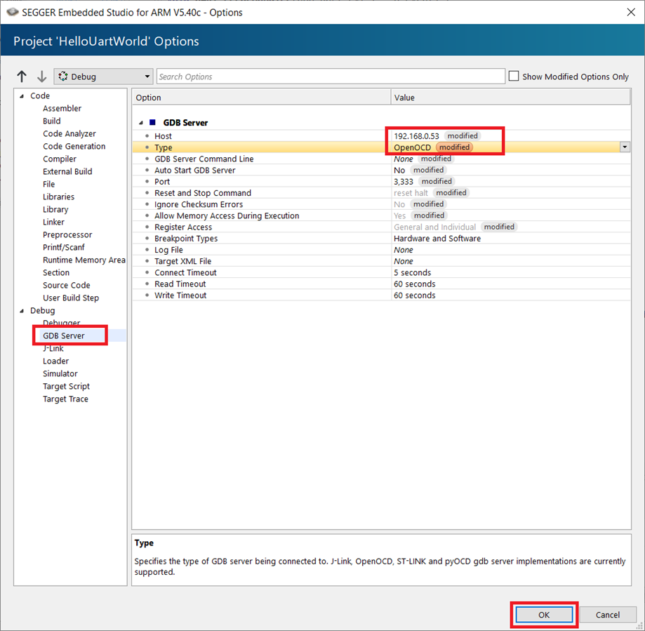
Then go to GDB Server tab and change Host to IP address of Raspberry Pi and change Type to OpenOCD. Then confirm by OK.
Now you can start debugging using F5 key. You should see marked first line of main because debugger restarted MCU and stopped CPU at main.

Place breakpoint on APP_UART_FIFO_INIT and press Continue in menu. Program will run until it breaks on any configured breakpoint.

Press F10 to step one line down. Your code will halt on condition checking for status of previous operation. You can hover mouse over status variable and view their content.

Then you can press continue to run program. Because there is no additional breakpoint it will run code and it will run infinite loop printing message. You can add breakpoints wherever you want and analyse behaviour of program, variable values and so on.
After every modification to program you must remember to do following steps:
- Stop previous debugging in SES.
- Press F7 in SES for building modified firmware.
- Copy new firmware to Raspberry Pi.
- Stop previous OpenOCD.
- Start new OpenOCD which flashes new firmware to device.
- Press F5 in SES to connect to newly running debugging server.
I created BAT (or sh file on Linux) file to automate part of this process with following content:
scp "C:\path_to_project\Output\Debug\Exe\HelloUartWorld.elf" pi@192.168.0.53:/home/pi/HelloUartWorld.elf
ssh pi@192.168.0.53 "pkill openocd"
ssh pi@192.168.0.53 "openocd -c 'bindto 0.0.0.0' -f rpi_as_debugger.cfg -c 'transport select swd' -c 'adapter speed 250' -f target/nrf52.cfg -c 'init' -c 'halt' -c 'nrf5 mass_erase' -c 'program HelloUartWorld.elf verify' -c 'reset'"
I also recommend configure SSH key connection method to reduce number of entering passwords. You must enter password on every scp and ssh command.
Restoring Backup Firmware
When you flashed new firmware to device, you completely lost Arduino Bootloader and possibility to use emulated serial over USB because our firmware has no logic for it. When you decide to go back to easy and user friendly Arduino environment you need to restore original firmware which you have backed up in one of previous sections. You need just execute command which flashes Arduino_nano_flash_backup.bin instead of HelloUartWorld.elf.
openocd -f rpi_as_debugger.cfg -c 'transport select swd' -c 'adapter speed 250' -f target/nrf52.cfg -c 'init' -c 'halt' -c 'nrf5 mass_erase' -c 'program arduino_nano_flash_backup.bin verify' -c 'reset'
Summary
This is all for this tutorial. You have seen how to develop application nRF52840 native application using Segger Embeded Studio and how to debug it using Raspberry Pi instead of any common JTAG/SWD debug probe.
My opinions about this complicated process, library, and SES you can find in chapter “Review of Software”.

