RoadTest: Seeking a Tech Enthusiast to Evaluate the Arduino GIGA Display Bundle
Author: dougw
Creation date:
Evaluation Type: Connectors & Cable
Did you receive all parts the manufacturer stated would be included in the package?: False
What other parts do you consider comparable to this product?: The Arduino Giga is the same form factor as an Arduino Mega, however the Giga is significantly improved in a great many ways..
What were the biggest problems encountered?: The biggest problem was trying to test the vast array of features in this kit.
Detailed Review:
Every once in a while a microcontroller module comes along that stands out as a significant step forward. The Arduino GIGA is one of hose modules. When I read the specifications and features, I knew I wanted to check it out and see what it could do. Fortunately I was chosen to put it through some paces. This blog chronicles that journey. It isn't a standard road test that focusses on explaining features and testing specifications. what I wanted to do was develop a series of mini applications that go beyond what the example sketches actually do, to showcase that when the feature set is comprehensive enough, they synergize to make the sum of the features greater than the individual features. The Arduino Giga exemplifies a platform that is so feature rich it can adapt to implement more complex applications than perhaps any microcontroller available today. I hope to show that saying it has more horsepower, more memory and more IO is insufficient to describe how much better it actually is than microcontrollers that came before.
Here is a picture of the GIGA with its companion LCD displaying a color picture - just to get things started with a splash:
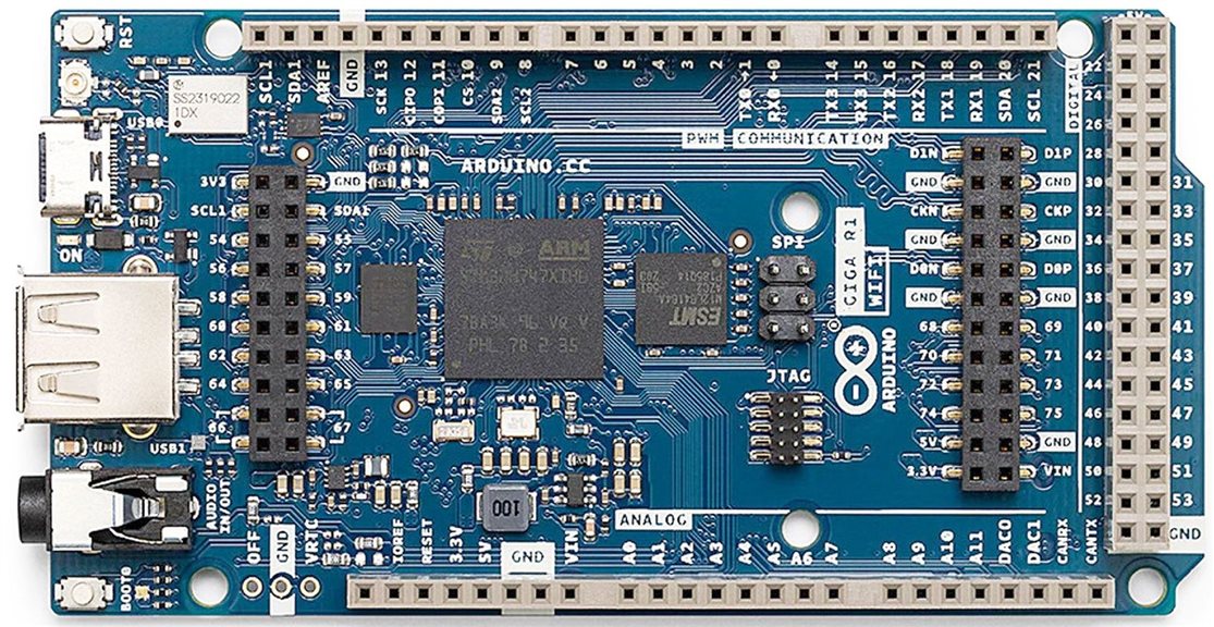
You can already see the display is a gorgeous 800x480 LCD, but I'm getting ahead of the journey.
The journey started with unboxing accompanied by a little Giga song I concocted. This video includes installation of an Arducam GC2145, procured separately from the road test kit. It also includes installation of the whole system in a 3D printed chassis, to make demonstrations a bit more robust. Finally the first video incudes powering on to display a first image:
One of the really impressive things about this display is how fast it can display a full image. This speed allows it to display video which is problematic on most small microcontroller displays.
The second video shows how to display images stored in onboard memory. The GIGA has 2 MB of Flash and 1 MB of RAM.
Full images for the 800x480 display take 750KB, so even though there is lots of onboard memory, it can't store very many full images.
/*
aball image display
by Doug Wong
*/

#include "Arduino_H7_Video.h"
#include "ArduinoGraphics.h"

// Alternatively, any raw RGB565 image can be included on demand using this macro
// Online image converter: https://lvgl.io/tools/imageconverter (Output format: Binary RGB565)

#define INCBIN_PREFIX
#include "incbin.h"
INCBIN(test, "F:/projects/arduino/GigaR1/demos/aball1.bin");

Arduino_H7_Video Display(800, 480, GigaDisplayShield);

Image img_aball1(ENCODING_RGB16, (uint8_t *) testData, 800, 480);

void setup() {
  Display.begin();

  Display.beginDraw();
  Display.image(img_aball1, (Display.width() - img_aball1.width())/2, (Display.height() - img_aball1.height())/2);
  Display.endDraw();
}

void loop() { }
This program also uses a incbin.h program to load an image into memory.
/**
 * @file incbin.h
 * @author Dale Weiler
 * @brief Utility for including binary files
 *
 * Facilities for including binary files into the current translation unit and
 * making use from them externally in other translation units.
 */
#ifndef INCBIN_HDR
#define INCBIN_HDR
#include <limits.h>
#if   defined(__AVX512BW__) || \
      defined(__AVX512CD__) || \
      defined(__AVX512DQ__) || \
      defined(__AVX512ER__) || \
      defined(__AVX512PF__) || \
      defined(__AVX512VL__) || \
      defined(__AVX512F__)
# define INCBIN_ALIGNMENT_INDEX 6
#elif defined(__AVX__)      || \
      defined(__AVX2__)
# define INCBIN_ALIGNMENT_INDEX 5
#elif defined(__SSE__)      || \
      defined(__SSE2__)     || \
      defined(__SSE3__)     || \
      defined(__SSSE3__)    || \
      defined(__SSE4_1__)   || \
      defined(__SSE4_2__)   || \
      defined(__neon__)
# define INCBIN_ALIGNMENT_INDEX 4
#elif ULONG_MAX != 0xffffffffu
# define INCBIN_ALIGNMENT_INDEX 3
# else
# define INCBIN_ALIGNMENT_INDEX 2
#endif

/* Lookup table of (1 << n) where `n' is `INCBIN_ALIGNMENT_INDEX' */
#define INCBIN_ALIGN_SHIFT_0 1
#define INCBIN_ALIGN_SHIFT_1 2
#define INCBIN_ALIGN_SHIFT_2 4
#define INCBIN_ALIGN_SHIFT_3 8
#define INCBIN_ALIGN_SHIFT_4 16
#define INCBIN_ALIGN_SHIFT_5 32
#define INCBIN_ALIGN_SHIFT_6 64

/* Actual alignment value */
#define INCBIN_ALIGNMENT \
    INCBIN_CONCATENATE( \
        INCBIN_CONCATENATE(INCBIN_ALIGN_SHIFT, _), \
        INCBIN_ALIGNMENT_INDEX)

/* Stringize */
#define INCBIN_STR(X) \
    #X
#define INCBIN_STRINGIZE(X) \
    INCBIN_STR(X)
/* Concatenate */
#define INCBIN_CAT(X, Y) \
    X ## Y
#define INCBIN_CONCATENATE(X, Y) \
    INCBIN_CAT(X, Y)
/* Deferred macro expansion */
#define INCBIN_EVAL(X) \
    X
#define INCBIN_INVOKE(N, ...) \
    INCBIN_EVAL(N(__VA_ARGS__))

/* Green Hills uses a different directive for including binary data */
#if defined(__ghs__)
#  if (__ghs_asm == 2)
#    define INCBIN_MACRO ".file"
/* Or consider the ".myrawdata" entry in the ld file */
#  else
#    define INCBIN_MACRO "\tINCBIN"
#  endif
#else
#  define INCBIN_MACRO ".incbin"
#endif

#ifndef _MSC_VER
#  define INCBIN_ALIGN \
    __attribute__((aligned(INCBIN_ALIGNMENT)))
#else
#  define INCBIN_ALIGN __declspec(align(INCBIN_ALIGNMENT))
#endif

#if defined(__arm__) || /* GNU C and RealView */ \
    defined(__arm) || /* Diab */ \
    defined(_ARM) /* ImageCraft */
#  define INCBIN_ARM
#endif

#ifdef __GNUC__
/* Utilize .balign where supported */
#  define INCBIN_ALIGN_HOST ".balign " INCBIN_STRINGIZE(INCBIN_ALIGNMENT) "\n"
#  define INCBIN_ALIGN_BYTE ".balign 1\n"
#elif defined(INCBIN_ARM)
/*
 * On arm assemblers, the alignment value is calculated as (1 << n) where `n' is
 * the shift count. This is the value passed to `.align'
 */
#  define INCBIN_ALIGN_HOST ".align " INCBIN_STRINGIZE(INCBIN_ALIGNMENT_INDEX) "\n"
#  define INCBIN_ALIGN_BYTE ".align 0\n"
#else
/* We assume other inline assembler's treat `.align' as `.balign' */
#  define INCBIN_ALIGN_HOST ".align " INCBIN_STRINGIZE(INCBIN_ALIGNMENT) "\n"
#  define INCBIN_ALIGN_BYTE ".align 1\n"
#endif

/* INCBIN_CONST is used by incbin.c generated files */
#if defined(__cplusplus)
#  define INCBIN_EXTERNAL extern "C"
#  define INCBIN_CONST    extern const
#else
#  define INCBIN_EXTERNAL extern
#  define INCBIN_CONST    const
#endif

/**
 * @brief Optionally override the linker section into which data is emitted.
 *
 * @warning If you use this facility, you'll have to deal with platform-specific linker output
 * section naming on your own
 *
 * Overriding the default linker output section, e.g for esp8266/Arduino:
 * @code
 * #define INCBIN_OUTPUT_SECTION ".irom.text"
 * #include "incbin.h"
 * INCBIN(Foo, "foo.txt");
 * // Data is emitted into program memory that never gets copied to RAM
 * @endcode
 */
#if !defined(INCBIN_OUTPUT_SECTION)
#  if defined(__APPLE__)
#    define INCBIN_OUTPUT_SECTION         ".const_data"
#  else
#    define INCBIN_OUTPUT_SECTION         ".rodata"
#  endif
#endif

#if defined(__APPLE__)
/* The directives are different for Apple branded compilers */
#  define INCBIN_SECTION         INCBIN_OUTPUT_SECTION "\n"
#  define INCBIN_GLOBAL(NAME)    ".globl " INCBIN_MANGLE INCBIN_STRINGIZE(INCBIN_PREFIX) #NAME "\n"
#  define INCBIN_INT             ".long "
#  define INCBIN_MANGLE          "_"
#  define INCBIN_BYTE            ".byte "
#  define INCBIN_TYPE(...)
#else
#  define INCBIN_SECTION         ".section " INCBIN_OUTPUT_SECTION "\n"
#  define INCBIN_GLOBAL(NAME)    ".global " INCBIN_STRINGIZE(INCBIN_PREFIX) #NAME "\n"
#  if defined(__ghs__)
#    define INCBIN_INT           ".word "
#  else
#    define INCBIN_INT           ".int "
#  endif
#  if defined(__USER_LABEL_PREFIX__)
#    define INCBIN_MANGLE        INCBIN_STRINGIZE(__USER_LABEL_PREFIX__)
#  else
#    define INCBIN_MANGLE        ""
#  endif
#  if defined(INCBIN_ARM)
/* On arm assemblers, `@' is used as a line comment token */
#    define INCBIN_TYPE(NAME)    ".type " INCBIN_STRINGIZE(INCBIN_PREFIX) #NAME ", %object\n"
#  elif defined(__MINGW32__) || defined(__MINGW64__)
/* Mingw doesn't support this directive either */
#    define INCBIN_TYPE(NAME)
#  else
/* It's safe to use `@' on other architectures */
#    define INCBIN_TYPE(NAME)    ".type " INCBIN_STRINGIZE(INCBIN_PREFIX) #NAME ", @object\n"
#  endif
#  define INCBIN_BYTE            ".byte "
#endif

/* List of style types used for symbol names */
#define INCBIN_STYLE_CAMEL 0
#define INCBIN_STYLE_SNAKE 1

/**
 * @brief Specify the prefix to use for symbol names.
 *
 * By default this is `g', producing symbols of the form:
 * @code
 * #include "incbin.h"
 * INCBIN(Foo, "foo.txt");
 *
 * // Now you have the following symbols:
 * // const unsigned char gFooData[];
 * // const unsigned char *const gFooEnd;
 * // const unsigned int gFooSize;
 * @endcode
 *
 * If however you specify a prefix before including: e.g:
 * @code
 * #define INCBIN_PREFIX incbin
 * #include "incbin.h"
 * INCBIN(Foo, "foo.txt");
 *
 * // Now you have the following symbols instead:
 * // const unsigned char incbinFooData[];
 * // const unsigned char *const incbinFooEnd;
 * // const unsigned int incbinFooSize;
 * @endcode
 */
#if !defined(INCBIN_PREFIX)
#  define INCBIN_PREFIX g
#endif

/**
 * @brief Specify the style used for symbol names.
 *
 * Possible options are
 * - INCBIN_STYLE_CAMEL "CamelCase"
 * - INCBIN_STYLE_SNAKE "snake_case"
 *
 * Default option is *INCBIN_STYLE_CAMEL* producing symbols of the form:
 * @code
 * #include "incbin.h"
 * INCBIN(Foo, "foo.txt");
 *
 * // Now you have the following symbols:
 * // const unsigned char <prefix>FooData[];
 * // const unsigned char *const <prefix>FooEnd;
 * // const unsigned int <prefix>FooSize;
 * @endcode
 *
 * If however you specify a style before including: e.g:
 * @code
 * #define INCBIN_STYLE INCBIN_STYLE_SNAKE
 * #include "incbin.h"
 * INCBIN(foo, "foo.txt");
 *
 * // Now you have the following symbols:
 * // const unsigned char <prefix>foo_data[];
 * // const unsigned char *const <prefix>foo_end;
 * // const unsigned int <prefix>foo_size;
 * @endcode
 */
#if !defined(INCBIN_STYLE)
#  define INCBIN_STYLE INCBIN_STYLE_CAMEL
#endif

/* Style lookup tables */
#define INCBIN_STYLE_0_DATA Data
#define INCBIN_STYLE_0_END End
#define INCBIN_STYLE_0_SIZE Size
#define INCBIN_STYLE_1_DATA _data
#define INCBIN_STYLE_1_END _end
#define INCBIN_STYLE_1_SIZE _size

/* Style lookup: returning identifier */
#define INCBIN_STYLE_IDENT(TYPE) \
    INCBIN_CONCATENATE( \
        INCBIN_STYLE_, \
        INCBIN_CONCATENATE( \
            INCBIN_EVAL(INCBIN_STYLE), \
            INCBIN_CONCATENATE(_, TYPE)))

/* Style lookup: returning string literal */
#define INCBIN_STYLE_STRING(TYPE) \
    INCBIN_STRINGIZE( \
        INCBIN_STYLE_IDENT(TYPE)) \

/* Generate the global labels by indirectly invoking the macro with our style
 * type and concatenating the name against them. */
#define INCBIN_GLOBAL_LABELS(NAME, TYPE) \
    INCBIN_INVOKE( \
        INCBIN_GLOBAL, \
        INCBIN_CONCATENATE( \
            NAME, \
            INCBIN_INVOKE( \
                INCBIN_STYLE_IDENT, \
                TYPE))) \
    INCBIN_INVOKE( \
        INCBIN_TYPE, \
        INCBIN_CONCATENATE( \
            NAME, \
            INCBIN_INVOKE( \
                INCBIN_STYLE_IDENT, \
                TYPE)))

/**
 * @brief Externally reference binary data included in another translation unit.
 *
 * Produces three external symbols that reference the binary data included in
 * another translation unit.
 *
 * The symbol names are a concatenation of `INCBIN_PREFIX' before *NAME*; with
 * "Data", as well as "End" and "Size" after. An example is provided below.
 *
 * @param NAME The name given for the binary data
 *
 * @code
 * INCBIN_EXTERN(Foo);
 *
 * // Now you have the following symbols:
 * // extern const unsigned char <prefix>FooData[];
 * // extern const unsigned char *const <prefix>FooEnd;
 * // extern const unsigned int <prefix>FooSize;
 * @endcode
 */
#define INCBIN_EXTERN(NAME) \
    INCBIN_EXTERNAL const INCBIN_ALIGN unsigned char \
        INCBIN_CONCATENATE( \
            INCBIN_CONCATENATE(INCBIN_PREFIX, NAME), \
            INCBIN_STYLE_IDENT(DATA))[]; \
    INCBIN_EXTERNAL const INCBIN_ALIGN unsigned char *const \
    INCBIN_CONCATENATE( \
        INCBIN_CONCATENATE(INCBIN_PREFIX, NAME), \
        INCBIN_STYLE_IDENT(END)); \
    INCBIN_EXTERNAL const unsigned int \
        INCBIN_CONCATENATE( \
            INCBIN_CONCATENATE(INCBIN_PREFIX, NAME), \
            INCBIN_STYLE_IDENT(SIZE))

/**
 * @brief Include a binary file into the current translation unit.
 *
 * Includes a binary file into the current translation unit, producing three symbols
 * for objects that encode the data and size respectively.
 *
 * The symbol names are a concatenation of `INCBIN_PREFIX' before *NAME*; with
 * "Data", as well as "End" and "Size" after. An example is provided below.
 *
 * @param NAME The name to associate with this binary data (as an identifier.)
 * @param FILENAME The file to include (as a string literal.)
 *
 * @code
 * INCBIN(Icon, "icon.png");
 *
 * // Now you have the following symbols:
 * // const unsigned char <prefix>IconData[];
 * // const unsigned char *const <prefix>IconEnd;
 * // const unsigned int <prefix>IconSize;
 * @endcode
 *
 * @warning This must be used in global scope
 * @warning The identifiers may be different if INCBIN_STYLE is not default
 *
 * To externally reference the data included by this in another translation unit
 * please @see INCBIN_EXTERN.
 */
#ifdef _MSC_VER
#define INCBIN(NAME, FILENAME) \
    INCBIN_EXTERN(NAME)
#else
#define INCBIN(NAME, FILENAME) \
    __asm__(INCBIN_SECTION \
            INCBIN_GLOBAL_LABELS(NAME, DATA) \
            INCBIN_ALIGN_HOST \
            INCBIN_MANGLE INCBIN_STRINGIZE(INCBIN_PREFIX) #NAME INCBIN_STYLE_STRING(DATA) ":\n" \
            INCBIN_MACRO " \"" FILENAME "\"\n" \
            INCBIN_GLOBAL_LABELS(NAME, END) \
            INCBIN_ALIGN_BYTE \
            INCBIN_MANGLE INCBIN_STRINGIZE(INCBIN_PREFIX) #NAME INCBIN_STYLE_STRING(END) ":\n" \
                INCBIN_BYTE "1\n" \
            INCBIN_GLOBAL_LABELS(NAME, SIZE) \
            INCBIN_ALIGN_HOST \
            INCBIN_MANGLE INCBIN_STRINGIZE(INCBIN_PREFIX) #NAME INCBIN_STYLE_STRING(SIZE) ":\n" \
                INCBIN_INT INCBIN_MANGLE INCBIN_STRINGIZE(INCBIN_PREFIX) #NAME INCBIN_STYLE_STRING(END) " - " \
                           INCBIN_MANGLE INCBIN_STRINGIZE(INCBIN_PREFIX) #NAME INCBIN_STYLE_STRING(DATA) "\n" \
            INCBIN_ALIGN_HOST \
            ".text\n" \
    ); \
    INCBIN_EXTERN(NAME)

#endif
#endif
In keeping with my goal to go beyond what the example sketches can do, this sketch can load images from a USB memory stick by touching the screen.
This is a complete slide show app.
// Arduino GIGA R1 program to display images stored on a USB memory device
// by Doug Wong 2025
// Touching the screen displays the next image
// The image will roll over to thr first image after the last image
// Image format should be 800 x 480 in RGB565 format - binary

#include <Arduino_USBHostMbed5.h>
#include <DigitalOut.h>
#include <FATFileSystem.h>
#include <Arduino_H7_Video.h>
#include <ArduinoGraphics.h>
#include "Arduino_GigaDisplayTouch.h"

Arduino_GigaDisplayTouch touchDetector;

USBHostMSD msd;
mbed::FATFileSystem usb("usb");

const int USB_HOST_ENABLE_PIN = PA_15;
const int MAX_FILES = 50;
const int MAX_NAME_LEN = 128;
char fileNames[MAX_FILES][MAX_NAME_LEN];
int fileCount = 0;
const int MAX_CONNECTION_ATTEMPTS = 10;
int filenum = 0;                        // file number selected

Arduino_H7_Video Display(800, 480, GigaDisplayShield);
const int IMG_WIDTH = 800;
const int IMG_HEIGHT = 480;
const uint32_t EXPECTED_FILE_SIZE = IMG_WIDTH * IMG_HEIGHT * 2;

uint8_t rowBuffer[IMG_WIDTH * 2]; // Static buffer

void setup() {
    Serial.begin(115200);
    touchDetector.begin();
    pinMode(USB_HOST_ENABLE_PIN, OUTPUT);
    digitalWrite(USB_HOST_ENABLE_PIN, HIGH);
    while (!Serial) {}
    delay(1500);

    Serial.println("=== USB File List ===");
    Display.begin();
    forceScreenClear();

    if (!initUSBHost() || !mountUSB()) return;
    listRootDirectory();
    if (fileCount == 0) return;

    printFileList();
    Serial.println("Select a file # to open as 800x480 .bin, or type 'clear' to reset the screen:");
}

void loop() {
    if (fileCount > 0) handleUserInput();
    uint8_t contacts;
    GDTpoint_t points[5];

    contacts = touchDetector.getTouchPoints(points);  //capture touches on touchscreen
    if (contacts > 0) {                               //Check for screen touch
        filenum++;                                    //increment filenumber
        if (filenum > fileCount)  filenum = 1;        //handle rollover when filenum exceeds filecount
        displayRawRowByRow(fileNames[filenum-1]);     //call image disply of file number
    }
    contacts = touchDetector.getTouchPoints(points);  //check screen for touches - should br none at this time
    contacts = 0;                                     //clear any touch count anyway
    delay (20);
}

bool initUSBHost() {
    for (int i = 0; i < MAX_CONNECTION_ATTEMPTS; i++) {
        if (msd.connect()) {
            Serial.println("USB mass storage device connected!");
            return true;
        }
        Serial.println("USB device not detected, retrying...");
        delay(1000);
    }
    return false;
}

bool mountUSB() {
    Serial.print("Mounting USB device... ");
    if (usb.mount(&msd)) {
        Serial.println("Failed to mount USB.");
        return false;
    }
    Serial.println("done.");
    return true;
}

void listRootDirectory() {
    fileCount = 0;
    DIR* dir = opendir("/usb/");
    if (!dir) return;
    while (fileCount < MAX_FILES) {
        struct dirent* entry = readdir(dir);
        if (!entry) break;
        strncpy(fileNames[fileCount], entry->d_name, MAX_NAME_LEN - 1);
        fileNames[fileCount][MAX_NAME_LEN - 1] = '\0';
        fileCount++;
    }
    closedir(dir);
}

void printFileList() {
    Serial.print("Found "); Serial.print(fileCount); Serial.println(" file(s) in /usb/:");
    for (int i = 0; i < fileCount; i++) {
        Serial.print(i + 1); Serial.print(") "); Serial.println(fileNames[i]);
    }
}

void handleUserInput() {
    if (Serial.available() > 0) {
        String input = Serial.readStringUntil('\n');
        input.trim();

        if (input.equalsIgnoreCase("clear")) {
            forceScreenClear();
            return;
        }

        int sel = input.toInt();
        if (sel < 1 || sel > fileCount) return;

        Serial.print("Displaying: /usb/");
        Serial.println(fileNames[sel - 1]);

        displayRawRowByRow(fileNames[sel - 1]);
    }
}

bool displayRawRowByRow(const char* fileName) {
    String path = "/usb/" + String(fileName);
    FILE* f = fopen(path.c_str(), "rb");
    if (!f) return false;

    forceScreenClear();
    Display.beginDraw();

    for (int y = 0; y < IMG_HEIGHT; y++) {
        if (fread(rowBuffer, 1, IMG_WIDTH * 2, f) != IMG_WIDTH * 2) break;
        Image rowImage(ENCODING_RGB16, rowBuffer, IMG_WIDTH, 1);
        Display.image(rowImage, 0, y);
    }

    Display.endDraw();
    fclose(f);
    Serial.println("Image displayed successfully!");
    return true;
}

void forceScreenClear() {
    Display.beginDraw();
    Display.fill(0x0000);
    Display.endDraw();
}
Next I moved on to see how the Arducam B0462 worked. The Giga has a connector for a camera which is passed through to the LCD module so it is simply plug and play.
Here is the Arducam displaying what it sees, which in this case is the camera I use to take videos for this blog.
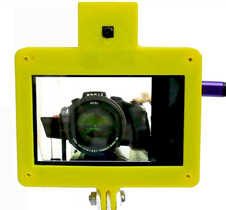
Currently the camera captures 320x240 pixels and upscales to 640x480. Hopefully the driver will get updated to capture a full 800x480.
Actually, I don't think I needed to swap horizontal orientation, but that is an easy fix.
//Arduino GIGA R1 displaying an Arducam B0462 (GC2145) on the GIGA Display
// Doug Wong 2025
// The GC2145 image has been transposed properly so it dsplays right side up

#include "arducam_dvp.h"
#include "Arduino_H7_Video.h"
#include "dsi.h"
#include "SDRAM.h"

// This example only works with Greyscale cameras (due to the palette + resize&rotate algo)
#define ARDUCAM_CAMERA_GC2145

#ifdef ARDUCAM_CAMERA_HM01B0
#include "Himax_HM01B0/himax.h"
HM01B0 himax;
Camera cam(himax);
#define IMAGE_MODE CAMERA_GRAYSCALE
#elif defined(ARDUCAM_CAMERA_HM0360)
#include "Himax_HM0360/hm0360.h"
HM0360 himax;
Camera cam(himax);
#define IMAGE_MODE CAMERA_GRAYSCALE
#elif defined(ARDUCAM_CAMERA_OV767X)
#include "OV7670/ov767x.h"
// OV7670 ov767x;
OV7675 ov767x;
Camera cam(ov767x);
#define IMAGE_MODE CAMERA_RGB565
#elif defined(ARDUCAM_CAMERA_GC2145)
#include "GC2145/gc2145.h"
GC2145 galaxyCore;
Camera cam(galaxyCore);
#define IMAGE_MODE CAMERA_RGB565
#endif

// The buffer used to capture the frame
FrameBuffer fb;
// The buffer used to rotate and resize the frame
FrameBuffer outfb;
// The buffer used to rotate and resize the frame
Arduino_H7_Video Display(800, 480, GigaDisplayShield);

void blinkLED(uint32_t count = 0xFFFFFFFF)
{
  pinMode(LED_BUILTIN, OUTPUT);
  while (count--) {
    digitalWrite(LED_BUILTIN, LOW);  // turn the LED on (HIGH is the voltage level)
    delay(50);                       // wait for a second
    digitalWrite(LED_BUILTIN, HIGH); // turn the LED off by making the voltage LOW
    delay(50);                       // wait for a second
  }
}

uint32_t palette[256];

void setup() {
  // Init the cam QVGA, 30FPS
  if (!cam.begin(CAMERA_R320x240, IMAGE_MODE, 30)) {
    blinkLED();
  }

  // Setup the palette to convert 8 bit greyscale to 32bit greyscale
  for (int i = 0; i < 256; i++) {
    palette[i] = 0xFF000000 | (i << 16) | (i << 8) | i;
  }

  Display.begin();

  if (IMAGE_MODE == CAMERA_GRAYSCALE) {
    dsi_configueCLUT((uint32_t*)palette);
  }
  outfb.setBuffer((uint8_t*)SDRAM.malloc(1024 * 1024));

  // clear the display (gives a nice black background)
  dsi_lcdClear(0);
  dsi_drawCurrentFrameBuffer();
  dsi_lcdClear(0);
  dsi_drawCurrentFrameBuffer();
}

#define HTONS(x)    (((x >> 8) & 0x00FF) | ((x << 8) & 0xFF00))

void loop() {

  // Grab frame and write to another framebuffer
  if (cam.grabFrame(fb, 3000) == 0) {

    // double the resolution and transpose (rotate by 90 degrees) in the same step
    // this only works if the camera feed is 320x240 and the area where we want to display is 640x480
    for (int i = 0; i < 320; i++) {
      int k = 320 - i;                    // this coordinate reversal swaps the image horizontally
      for (int j = 0; j < 240; j++) {
        int l = 240 - j;                  // this coordinate reversal swaps the image vertically
        if (IMAGE_MODE == CAMERA_GRAYSCALE) {
          ((uint8_t*)outfb.getBuffer())[j * 2 + (i * 2) * 480] = ((uint8_t*)fb.getBuffer())[i + j * 320];
          ((uint8_t*)outfb.getBuffer())[j * 2 + (i * 2) * 480 + 1] = ((uint8_t*)fb.getBuffer())[i + j * 320];
          ((uint8_t*)outfb.getBuffer())[j * 2 + (i * 2 + 1) * 480] = ((uint8_t*)fb.getBuffer())[i + j * 320];
          ((uint8_t*)outfb.getBuffer())[j * 2 + (i * 2 + 1) * 480 + 1] = ((uint8_t*)fb.getBuffer())[i + j * 320];
        } else {
          ((uint16_t*)outfb.getBuffer())[l * 2 + (k * 2) * 480] = HTONS(((uint16_t*)fb.getBuffer())[i + j * 320]);
          ((uint16_t*)outfb.getBuffer())[l * 2 + (k * 2) * 480 + 1] = HTONS(((uint16_t*)fb.getBuffer())[i + j * 320]);
          ((uint16_t*)outfb.getBuffer())[l * 2 + (k * 2 + 1) * 480] = HTONS(((uint16_t*)fb.getBuffer())[i + j * 320]);
          ((uint16_t*)outfb.getBuffer())[l * 2 + (k * 2 + 1) * 480 + 1] = HTONS(((uint16_t*)fb.getBuffer())[i + j * 320]);
        }
      }
    }
    dsi_lcdDrawImage((void*)outfb.getBuffer(), (void*)dsi_getCurrentFrameBuffer(), 480, 640, IMAGE_MODE == CAMERA_GRAYSCALE ? DMA2D_INPUT_L8 : DMA2D_INPUT_RGB565);
    dsi_drawCurrentFrameBuffer();
  } else {
    blinkLED(20);
  }
}
I spent some time exploring audio applications of the Giga. It has a microphone in the display and a stereo audio output jack. Both are unusual features for most microcontroller modules, but the Giga has them built-in.
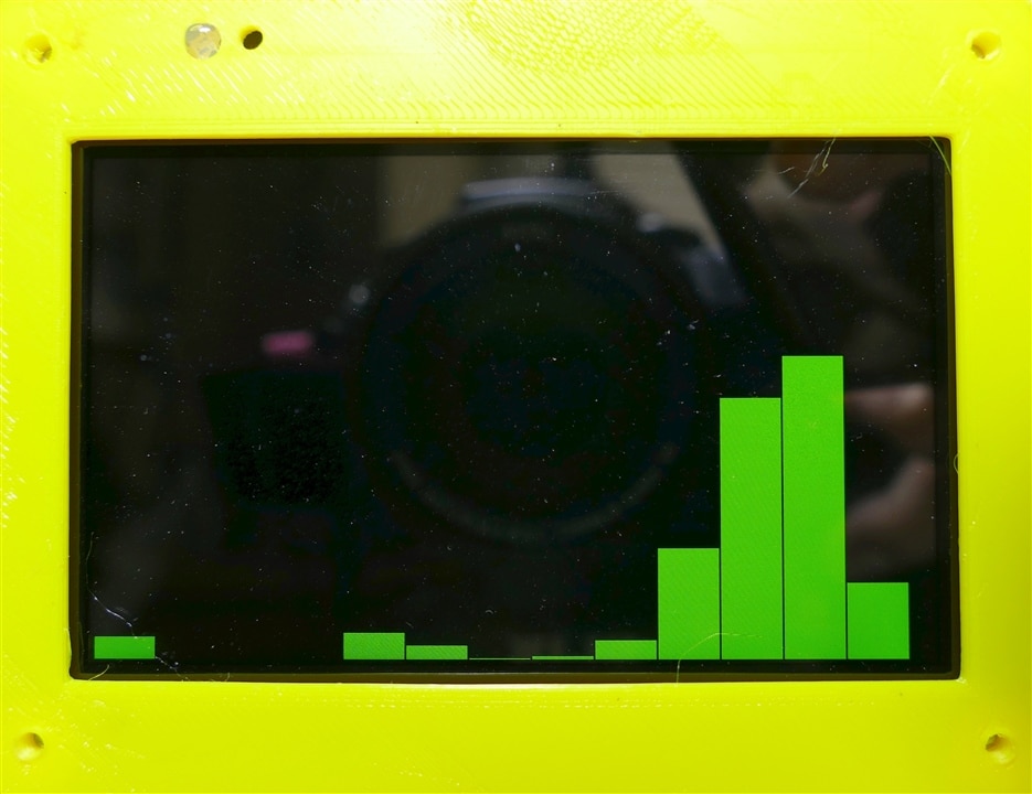
To demonstrate the microphone I am doing a VU Meter, which also shows that the display is lively, although the software slows down the activity to allow human eyes to keep up.
I also wanted to try a spectrum analyzer because the computer has enough speed to calculate FFTs and the display is also fast enough to display the results. This version doesn't try for a detailed spectrum (to reduce my programming time), although the hardware is certainly capable of it. The MCU is a dual core that includes both a 480 MHz ARM Cortex M7 and a 240 MHz ARM Cortex M4, which is about as fast as a decent PC from 1999.
/*
	Example of an audio spectrum analyzer display using the Arduino Giga Display and its microphone
  by Doug Wong 2025
  This program uses th FFT library by Enrique Condes
*/

#include "Arduino_GigaDisplay.h"
#include "arduinoFFT.h"
#include "Arduino_GigaDisplay_GFX.h"
#include <PDM.h>

GigaDisplay_GFX display; // Create the display object

#define SAMPLES 128           // Number of audio samples
#define BARS 16               // Number of spectrum bars
#define SAMPLING_FREQUENCY 16000  // Hz
#define GREEN 0x07E0
#define BLACK 0x0000
#define BLUE 0x001E

/*
These values can be changed in order to evaluate the functions
*/
const uint16_t samples = 128; //This value MUST ALWAYS be a power of 2
const double signalFrequency = 1000;
const double sampleFrequency = 16000;
static const int frequency = 16000;
static const char channels = 1;
const uint8_t amplitude = 100;
// static const int channels = 1;

short sampleBuffer[samples];

double vReal[samples];      //audio samples array
double vImag[samples];      //spectrum amplitudes
int iBar = SAMPLES / BARS;  //number of data points per bar
int barWidth = 2 * display.width() / BARS;  //number of pixels per bar
int barHeight;
int BarAmp;

int bytesAvailable = 128;   //in microphone buffer

/* Create FFT object */
ArduinoFFT<double> FFT = ArduinoFFT<double>(vReal, vImag, samples, sampleFrequency);

#define SCL_INDEX 0x00
#define SCL_TIME 0x01
#define SCL_FREQUENCY 0x02
#define SCL_PLOT 0x03

void setup()
{
  delay (400);
 // Serial.begin(115200);
  display.begin();
  display.setRotation(1);
  PDM.setBufferSize(samples);
  delay (400);
  display.fillScreen(BLACK);
  PDM.onReceive(onPDMdata);
    // Start PDM microphone
  if (!PDM.begin(channels, frequency)) {
    //Serial.println("Failed to start PDM!");
    while (1)
      ;
  }
}

void loop()
{
//  PDM.read(sampleBuffer, bytesAvailable);
  for (int i = 0; i < SAMPLES; i++) {
    vReal[i] = sampleBuffer[i];
    vImag[i] = 0.0;
  }

  FFT.windowing(vReal, samples, FFT_WIN_TYP_HAMMING, FFT_FORWARD);	/* Weigh data */
  FFT.compute(vReal, vImag, SAMPLES, FFT_FORWARD); /* Compute FFT */
  FFT.complexToMagnitude(vReal, vImag, SAMPLES); /* Compute magnitudes */

// Draw spectrum bars
  for (int i = 0; i < BARS; i++) {
    BarAmp = 0;
    for(int j = 0; j < iBar; j++) {
//       if (BarAmp < vImag[i * BARS + j]) BarAmp = vImag[i * BARS + j];
      BarAmp = BarAmp + vImag[i * BARS + j];    // total amplitude in each bar
    }
    if (i == 8) BarAmp = BarAmp / 20;           // to reduce an anomolously high bar
    BarAmp =  BarAmp / BARS;                    // average amplitube in this bar
    barHeight = BarAmp / 16;                    // adjustment for overall volume
    if (barHeight > display.height()) barHeight = display.height();
    display.fillRect(i * barWidth, 0, barWidth - 2, display.height() - barHeight, BLACK);
    display.fillRect(i * barWidth, display.height() - barHeight, barWidth - 2, barHeight, GREEN);
  }
  delay(80);
}

void onPDMdata() {
  // query the number of bytes available
  int bytesAvailable = PDM.available();

  // read into the sample buffer
  int bytesRead = PDM.read(sampleBuffer, bytesAvailable);

  // 16-bit, 2 bytes per sample
  int samplesRead = bytesRead / 2;
}
Now on to audio output. This requires an amplifier and speakers, so I roped in a single chip audio amp I designed a PCB for, and an orphan Logitech speaker I had kicking around.
I had been spoiled by how much was built-in to the Giga, which made this part of the road test seem a bit kluged, including making up some cables. However the audio sounded pretty good considering it uses a 12 bit DAC.
/*
 * GIGA WAV Player
 * GIGA R1 - Audio Playback of a wav file store on a USB memory device
 * Simple wav format audio playback via 12-Bit DAC output by reading from a USB drive.
 * This sketch assumes the USB memory device is named "USB"
 * This sketch assumes the audio file is named "GIGAchorus.wav"
 * by Doug Wong 2025
*/

#include <Arduino_AdvancedAnalog.h>
#include <DigitalOut.h>
#include <Arduino_USBHostMbed5.h>
#include <FATFileSystem.h>
#include "Arduino_GigaDisplay_GFX.h"

#define WHITE 0xffff
#define BLACK 0x0000
#define YELLOW 0xFFE0
#define CYAN 0x07FFF
#define PURPLE 0x8010

AdvancedDAC dac0(A12);

USBHostMSD msd;
mbed::FATFileSystem usb("USB");

GigaDisplay_GFX display;

FILE * file = nullptr;
int sample_size = 0;
int samples_count = 0;


void setup()
{
  Serial.begin(115200);
  while (!Serial);

  display.begin();
  display.setRotation(1); // Landscape mode
  display.fillScreen(PURPLE);
  display.setTextColor(YELLOW);
  display.setTextSize(8);
  display.setCursor(35, 200);
  display.println("GIGA WAV Player");
  delay(4000);
  display.fillScreen(PURPLE);
  display.setTextSize(4);
  display.setCursor(10, 10);
  display.println("Reading USB...");

  /* Enable power for HOST USB connector. */
  pinMode(PA_15, OUTPUT);
  digitalWrite(PA_15, HIGH);

  if (!msd.connect()) {
    display.println("Insert USB memory device");
    while (!msd.connect()) delay(100);
  }
  display.println("Mounting USB...");
  int const rc_mount = usb.mount(&msd);
  if (rc_mount)
  {
    display.println("Error mounting USB device ");
    display.println(rc_mount);
    return;
  }

  display.println("Opening audio file ...");

  /* 16-bit PCM Mono 16kHz realigned noise reduction */
  file = fopen("/USB/GigaChorus.wav", "rb");
  if (file == nullptr)
  {
    display.print("Error opening audio file: ");
    display.println(strerror(errno));
    return;
  }

  display.println("Reading audio header ...");

  delay(200);
  display.fillScreen(PURPLE);
  display.setTextSize(3);
  display.setCursor(10, 1);

  struct wav_header_t
  {
    char chunkID[4]; //"RIFF" = 0x46464952
    unsigned long chunkSize; //28 [+ sizeof(wExtraFormatBytes) + wExtraFormatBytes] + sum(sizeof(chunk.id) + sizeof(chunk.size) + chunk.size)
    char format[4]; //"WAVE" = 0x45564157
    char subchunk1ID[4]; //"fmt " = 0x20746D66
    unsigned long subchunk1Size; //16 [+ sizeof(wExtraFormatBytes) + wExtraFormatBytes]
    unsigned short audioFormat;
    unsigned short numChannels;
    unsigned long sampleRate;
    unsigned long byteRate;
    unsigned short blockAlign;
    unsigned short bitsPerSample;
  };

  wav_header_t header;
  fread(&header, sizeof(header), 1, file);

  display.println("WAV File Header read:");
  char msg[64] = {0};
  snprintf(msg, sizeof(msg), "File Type: %s", header.chunkID);
  display.println(msg);
  snprintf(msg, sizeof(msg), "File Size: %ld", header.chunkSize);
  display.println(msg);
  snprintf(msg, sizeof(msg), "WAV Marker: %s", header.format);
  display.println(msg);
  snprintf(msg, sizeof(msg), "Format Name: %s", header.subchunk1ID);
  display.println(msg);
  snprintf(msg, sizeof(msg), "Format Length: %ld", header.subchunk1Size);
  display.println(msg);
  snprintf(msg, sizeof(msg), "Format Type: %hd", header.audioFormat);
  display.println(msg);
  snprintf(msg, sizeof(msg), "Number of Channels: %hd", header.numChannels);
  display.println(msg);
  snprintf(msg, sizeof(msg), "Sample Rate: %ld", header.sampleRate);
  display.println(msg);
  snprintf(msg, sizeof(msg), "Sample Rate * Bits/Sample * Channels / 8: %ld", header.byteRate);
  display.println(msg);
  snprintf(msg, sizeof(msg), "Bits per Sample * Channels / 8: %hd", header.blockAlign);
  display.println(msg);
  snprintf(msg, sizeof(msg), "Bits per Sample: %hd", header.bitsPerSample);
  display.println(msg);

  /* Find the data section of the WAV file. */
  struct chunk_t
  {
    char ID[4];
    unsigned long size;
  };

  chunk_t chunk;
  snprintf(msg, sizeof(msg), "id\t" "size");
  display.println(msg);
  /* Find data chunk. */
  while (true)
  {
    fread(&chunk, sizeof(chunk), 1, file);
    snprintf(msg, sizeof(msg), "%c%c%c%c\t" "%li", chunk.ID[0], chunk.ID[1], chunk.ID[2], chunk.ID[3], chunk.size);
    display.println(msg);
    if (*(unsigned int *) &chunk.ID == 0x61746164)
      break;
    /* Skip chunk data bytes. */
    fseek(file, chunk.size, SEEK_CUR);
  }

  /* Determine number of samples. */
  sample_size = header.bitsPerSample / 8;
  samples_count = chunk.size * 8 / header.bitsPerSample;
  snprintf(msg, sizeof(msg), "Sample size = %i", sample_size); display.println(msg);
  snprintf(msg, sizeof(msg), "Samples count = %i", samples_count); display.println(msg);

  /* Configure the advanced DAC. */
  if (!dac0.begin(AN_RESOLUTION_12, header.sampleRate * 2, 256, 16))
  {
    display.println("Failed to start DAC1 !");
    return;
  }

  delay(1500);
  display.fillScreen(PURPLE);
  display.setCursor(50, 50);
  display.setTextSize(5);
  display.println("Playing ......");
  display.setCursor(50, 200);
  display.setTextSize(7);
  display.println("GIGAchorus.WAV");
}

void loop()
{
  if (dac0.available() && !feof(file))
  {
    /* Read data from file. */
    uint16_t sample_data[256] = {0};
    fread(sample_data, sample_size, 256, file);

    /* Get a free buffer for writing. */
    SampleBuffer buf = dac0.dequeue();

    /* Write data to buffer. */
    for (size_t i = 0; i < buf.size(); i++)
    {
      /* Scale down to 12 bit. */
      uint16_t const dac_val = ((static_cast<unsigned int>(sample_data[i])+32768)>>4) & 0x0fff;
      buf[i] = dac_val;
    }

    /* Write the buffer to DAC. */
    dac0.write(buf);
  }
}
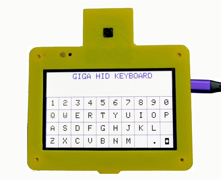
When I realized the Giga had a USB port capable of implementing a HID protocol, I had to try and implement a full HID QWERTY touch keyboard.
/*
HID Keyboard using arduino Giga Touch Display
by Doug Wong
2025
*/

//#include "ArduinoGraphics.h"
#include "PluggableUSBHID.h"
#include "USBKeyboard.h"
#include "Arduino_GigaDisplayTouch.h"
#include "Arduino_GigaDisplay_GFX.h"
#include "incbin.h"

#define BLACK 0x0000
#define WHITE 0xFFFF
#define RED 0xF800
#define YELLOW 0xFFE0
#define PURPLE 0xFB00
#define BLUE 0x001F

USBKeyboard Keyboard;
GigaDisplay_GFX display;
Arduino_GigaDisplayTouch touchDetector;

int ROW;
int COL;
int KEY;
char qwerty [41] = "1234567890QWERTYUIOPASDFGHJKL\nZXCVBNM .\b";   //keyboard characters

void setup() {
  display.begin();
  display.fillScreen(WHITE);
  display.setRotation(1);
  display.setTextSize(5);
  display.setTextColor(BLUE);
  display.setCursor(170, 10);
  display.print("GIGA HID KEYBOARD");
  display.setTextColor(BLACK);
  for (int i = 160; i <= 480; i+= 80) {   //draw hoizontal lines
  display.fillRect(0, i, 800, 2, BLUE);
  }
  for (int j = 0; j < 800; j+= 80) {      //draw vertical lines and display the keyboard characters
  display.fillRect(j, 160, 2, 320, BLUE);
  KEY = j / 80;
  display.setCursor(j+30, 180);
  display.print(qwerty[KEY]);
  KEY = j / 80 + 10;
  display.setCursor(j+30, 260);
  display.print(qwerty[KEY]);
  KEY = j / 80 + 20;
  display.setCursor(j+30, 340);
  display.print(qwerty[KEY]);
  KEY = j / 80 + 30;
  display.setCursor(j+30, 420);
  display.print(qwerty[KEY]);
  }

  display.setCursor(20, 60);        // set up to display which key was touched
  display.setTextColor(RED); // red text
  touchDetector.begin();
}

void loop() {
  uint8_t contacts;
  GDTpoint_t points[5];
  contacts = touchDetector.getTouchPoints(points);      //read the touch screen

  if (contacts > 0) {           // figure out the keaboard row that was touched
    if (points[0].x < 320) {
      if (points[0].x < 80) {
        ROW = 3;
    } else if (points[0].x < 160) {
        ROW = 2;
      } else if (points[0].x < 240) {
        ROW = 1;
    } else {
      ROW = 0;
    }
    if (points[0].y < 80) COL = 0;    // figure out the keaboard column that was touched
    else if (points[0].y < 160) COL = 1;
    else if (points[0].y < 240) COL = 2;
    else if (points[0].y < 320) COL = 3;
    else if (points[0].y < 400) COL = 4;
    else if (points[0].y < 480) COL = 5;
    else if (points[0].y < 560) COL = 6;
    else if (points[0].y < 640) COL = 7;
    else if (points[0].y < 720) COL = 8;
    else COL = 9;
    KEY = (ROW * 10 + COL);       // calculate which key was touched
    display.fillRect(0, 30, 100, 80, 0xFFFF);
    display.setCursor(20, 60);
    display.print(qwerty[KEY]);
    char tempCharString[2];
    tempCharString[0] = qwerty[KEY];
    tempCharString[1] = '\0';
    Keyboard.printf("%s", tempCharString);
  }

  for (int x = 0; x < 10; x++) {       //debounce touch
     contacts = touchDetector.getTouchPoints(points);
     if (contacts > 0) {
      x = 0;}   //you may want to time out to avoid a potential endless loop
     delay(10);
  }
  delay(100);
  contacts = 0;
 }
}
I have wanted to demonstrate a wireless application and this allowed me to explore the idea of using MQTT as a text messaging system. The idea is for users to publish and subscribe to a topic of mutual interest - forming an interest group that can text each other without needing a cell phone.
The Arduino GIGA with its display is an excellent platform to implement this functionality. It helped that I had already implemented a touch keyboard. Note the crude reflector on the right that allows me to see what the LED is doing.
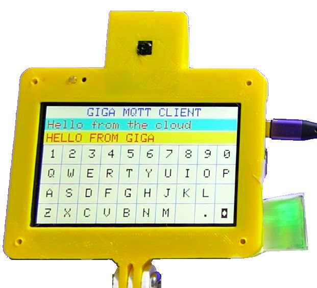
You will want to head over to the separate blog I did on this application for a more complete explanation of how to implement this capability.
//Arduino GIGA MQTT client example
//Touch keyboard publishes text messages to an MQTT broker
//It also subscribes to the a text chat topic
//It also subscribes to the LED topic, which controls the GIGA LED
//by Doug Wong 2025

#include "PluggableUSBHID.h"
#include "USBKeyboard.h"
#include "Arduino_GigaDisplayTouch.h"
#include "Arduino_GigaDisplay_GFX.h"
#include <WiFi.h>
#include <PubSubClient.h>
#include "creds.h"  // the following commented out code is included in creds.h

/* replace the capitallized text (only) with your own info & uncomment
const char* ssid = "WIFIACCESSPOINTNAME";
const char* pass = "ACCESSPOINTPASSWORD";
const char* username = "MQTTUSERNAME";
const char* password = "MQTTPASSWORD";
const char* mqtt_server = "MQTTBROKERURL";

const char* topic0 = "MQTTUSERNAME/feeds/TOPICNAME";
const char* topic1 = "MQTTUSERNAME/feeds/TOPICNAME";
*/

#define BLACK 0x0000
#define WHITE 0xFFFF
#define RED 0xF800
#define YELLOW 0xFFE0
#define PURPLE 0xFB00
#define BLUE 0x001F

USBKeyboard Keyboard;
GigaDisplay_GFX display;
Arduino_GigaDisplayTouch touchDetector;

WiFiClient espClient;
PubSubClient client(espClient);

int ROW;                //row number of the key being touched
int COL;                //column number of the key being touched
int KEY;                // KEY character index for the qwerty array
int curp = 0;           //cursor position on the display
char qwerty [41] = "1234567890QWERTYUIOPASDFGHJKL\nZXCVBNM .\b";   //keyboard characters
char mtxt [20];         //message txt to publish
bool sendt = false;     //publish flag to send text message
bool sendf = false;     //send flag to deal with broker echo
bool txt = false;       //flag to determine if the received message is text or LED

void setup() {
  pinMode(LED_BUILTIN, OUTPUT);     // Initialize the LED_BUILTIN pin as an output
  Serial.begin(115200);
  setup_wifi();
  client.setServer(mqtt_server, 1883);
  client.setCallback(callback);

  display.begin();
  display.fillScreen(WHITE);
  display.setRotation(1);             //set landscape orientation
  display.setTextSize(5);
  display.setTextColor(BLUE);
  display.setCursor(170, 6);
  display.print("GIGA MQTT CLIENT");
  display.setTextColor(BLACK);
  for (int i = 160; i <= 480; i+= 80) {   //draw hoizontal lines for the keyboard
  display.fillRect(0, i, 800, 2, BLUE);
  }
  for (int j = 0; j < 800; j+= 80) {      //draw vertical lines and display the keyboard characters
  display.fillRect(j, 160, 2, 320, BLUE);
  KEY = j / 80;
  display.setCursor(j+30, 180);
  display.print(qwerty[KEY]);
  KEY = j / 80 + 10;
  display.setCursor(j+30, 260);
  display.print(qwerty[KEY]);
  KEY = j / 80 + 20;
  display.setCursor(j+30, 340);
  display.print(qwerty[KEY]);
  KEY = j / 80 + 30;
  display.setCursor(j+30, 420);
  display.print(qwerty[KEY]);
  }

  display.setTextColor(RED); // red text
  touchDetector.begin();

  mtxt[19] = '\0';          //null character in case we want to use this array as a string
}

void setup_wifi() {

  delay(1500);
  //start by connecting to a WiFi network
  Serial.println();
  Serial.print("Connecting to ");
  Serial.println(ssid);

  WiFi.begin(ssid, pass);

  while (WiFi.status() != WL_CONNECTED) {
    delay(800);
    Serial.print(".");
  }

  Serial.println("");
  Serial.println("WiFi connected");
  Serial.println("IP address: ");
  Serial.println(WiFi.localIP());
}

void callback(char* topic, byte* payload, unsigned int length) { //when a message is received from a broker
  Serial.print("Message arrived [");
  Serial.print(topic);
  Serial.print("] ");
  for (int i = 0; i < length; i++) {
    Serial.print((char)payload[i]);
  }
  Serial.println();

   char lc = topic[strlen(topic) -1];
  if (lc == 't') txt = true;                  //look at the last character of the topic to determine what to do with the payload
  else txt = false;
  if (!txt && (char)payload[0] == '1') {      //if it is not a text message, use the payload to control the LED
    digitalWrite(LED_BUILTIN, LOW);   // Turn the LED on
  } else if (!txt && (char)payload[0] == '0') {
    digitalWrite(LED_BUILTIN, HIGH);  // Turn the LED off
  }
  if (txt) {
    if (sendf) {                              //if it is a txt message echo from a published message, display it in the transmit line
      sendf = false;
      display.fillRect(0, 105, 799, 50, 0xFFD0);
      display.setCursor(10, 114);
      for (int i = 0; i < length; i++) {
        display.print((char)payload[i]);
      }
    }
    else {                                    //if it is a fresh txt message, display it in the receive line
      display.fillRect(0, 50, 799, 50, 0x0FFF);
      display.setCursor(10, 59);
      for (int i = 0; i < length; i++) {
        display.print((char)payload[i]);
      }

    }
  }

}

void reconnect() {              // connect or reconnect to the MQTT broker

  while (!client.connected()) {
    Serial.print("Attempting MQTT connection...");
    // Create a random client ID
    String clientId = "ArduinoClient-";
    clientId += String(random(0xffff), HEX);
    // Attempt to connect
    if (client.connect(clientId.c_str(), username, password)) {
      Serial.println("connected");
      // Once connected, publish an announcement...
      //client.publish(topic0, "hello world");
      // ... and resubscribe
      client.subscribe(topic0);
      client.subscribe(topic1);
    } else {
      Serial.print("failed, rc=");
      Serial.print(client.state());
      Serial.println(" try again in 8 seconds");
      // Wait 10 seconds before retrying
      delay(2000);
    }
    delay(1000);
  }
}

void loop() {                 //loop to read keyboard touches and display text
  uint8_t contacts;
  GDTpoint_t points[5];

  if (!client.connected()) {
    reconnect();
  }

  client.loop();

  if (sendt) {
    sendt = false;
    sendf = true;
    Serial.print("Publish message: ");
    Serial.println(mtxt);
    client.publish(topic0, mtxt);
  }

 contacts = touchDetector.getTouchPoints(points);      //read the touch screen
  if (contacts > 0) {           // figure out the keaboard row that was touched
  if (points[0].x > 320) {
    points[0].x = 400;
    sendt = true;
    display.fillRect(0, 105, 799, 50, 0xFFEE);
    display.setCursor(10, 114);
    display.print(mtxt);
    }

  else if (points[0].x < 320) {
      if (points[0].x < 80) {
        ROW = 3;
    } else if (points[0].x < 160) {
        ROW = 2;
      } else if (points[0].x < 240) {
        ROW = 1;
    } else {
      ROW = 0;
    }
    if (points[0].y < 80) COL = 0;    // figure out the keaboard column that was touched
    else if (points[0].y < 160) COL = 1;
    else if (points[0].y < 240) COL = 2;
    else if (points[0].y < 320) COL = 3;
    else if (points[0].y < 400) COL = 4;
    else if (points[0].y < 480) COL = 5;
    else if (points[0].y < 560) COL = 6;
    else if (points[0].y < 640) COL = 7;
    else if (points[0].y < 720) COL = 8;
    else COL = 9;
    KEY = (ROW * 10 + COL);       // calculate which key was touched
    if (KEY == 39) {
      curp--;
      mtxt[curp] = 32;
      if (curp < 0) curp = 0;
    }
    else {
      mtxt[curp] = qwerty[KEY];
      curp++;
      if (curp > 18) curp = 18;
    }
      display.fillRect(0, 105, 799, 50, 0xFFE0);
      display.setCursor(10, 114);
      display.print(mtxt);
      display.setCursor(760, 114);
      display.print(">");

  }

  for (int x = 0; x < 10; x++) {       //debounce touch
     contacts = touchDetector.getTouchPoints(points);
     if (contacts > 0) {
      x = 0;}   //you may want to time out to avoid a potential endless loop
     delay(10);
  }
  delay(100);
  contacts = 0;
 }
}
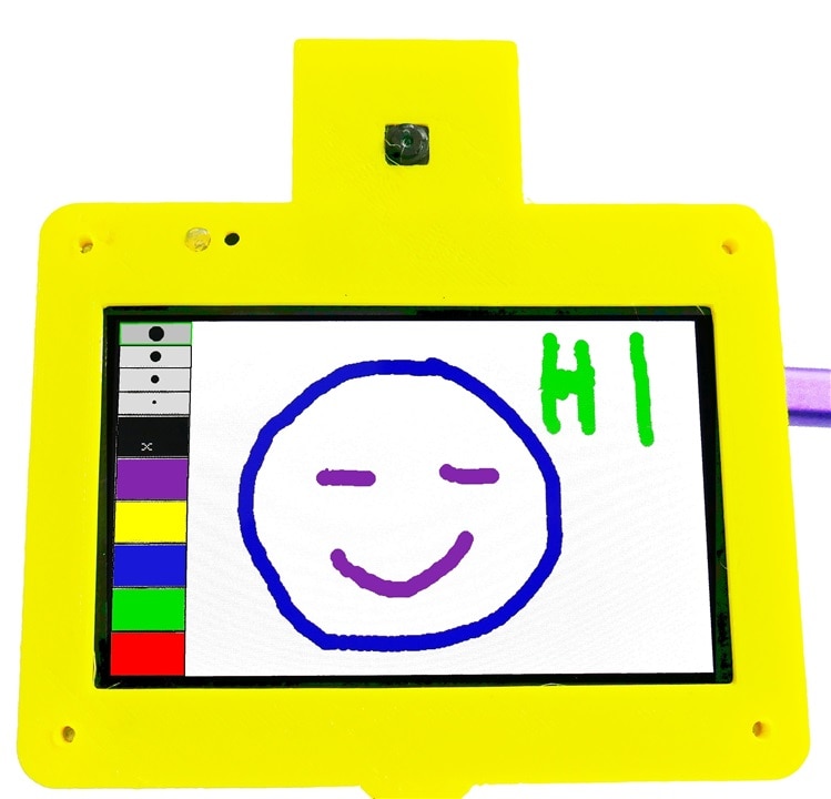
I wanted to include an application that is a fun, creative tool and a finger paint program fills that requirement.
// Giga Paint
//uses Arduino Giga and Giga Touch Display
// by Doug Wong 2025

#include "Arduino_GigaDisplay_GFX.h"
#include "Arduino_GigaDisplayTouch.h"

// --- Global Objects ---
// Create the GFX object for drawing
GigaDisplay_GFX display;
// Create the Touch object for reading touch input
Arduino_GigaDisplayTouch touch;

// --- Configuration Constants ---
// Use the display object to get dimensions
#define SCREEN_WIDTH  480  // GFX width is 480 (portrait by default)
#define SCREEN_HEIGHT 800  // GFX height is 800

// --- Palette and Control Bar Layout ---
const int CONTROL_BAR_HEIGHT = 100;
const int DRAWING_AREA_START_Y = CONTROL_BAR_HEIGHT;
const int PALETTE_COUNT = 5;
const int NIB_SIZES_COUNT = 4;
const int ERASER_INDEX = PALETTE_COUNT; // Index for the Eraser button
const int NIB_SELECTOR_START_X = 350;

// --- Colors and State ---
// Colors are defined in 16-bit RGB565 format (used by GFX)
#define RED     0xF800
#define GREEN   0x07E0
#define BLUE    0x001F
#define YELLOW  0xFFE0
#define MAGENTA 0xF81F
#define BLACK   0x0000
#define WHITE   0xFFFF
#define GREY    0x8410 // For control bar background

uint16_t colors[PALETTE_COUNT] = {RED, GREEN, BLUE, YELLOW, MAGENTA};
uint16_t currentColor = colors[0]; // Start with Red
uint16_t currentNibSize = 5;       // Start with a small size
int nibSizes[NIB_SIZES_COUNT] = {5, 10, 15, 20}; // Available nib sizes
bool isDrawing = false;
int lastX = -1;
int lastY = -1;

// --- Palette/Control Button Structure ---
const int PALETTE_BUTTON_WIDTH = (NIB_SELECTOR_START_X) / (PALETTE_COUNT + 1); // +1 for the eraser
struct ControlButton {
    int x;
    int y;
    int w;
    int h;
    uint16_t color;
    const char* label;
};
ControlButton paletteButtons[PALETTE_COUNT + 1]; // 5 colors + 1 eraser

void setup() {
    // Initialize Display and Touch
    display.begin();
    touch.begin();

    // Set default rotation (0 = portrait)
    display.setRotation(0);

    // Fill the screen with white to be the 'canvas'
    display.fillScreen(WHITE);

    // Initialize the control buttons array
    for (int i = 0; i < PALETTE_COUNT; i++) {
        paletteButtons[i] = {
            i * PALETTE_BUTTON_WIDTH,
            0,
            PALETTE_BUTTON_WIDTH,
            CONTROL_BAR_HEIGHT,
            colors[i],
            ""
        };
    }
    // Add the Eraser button
    paletteButtons[ERASER_INDEX] = {
        PALETTE_COUNT * PALETTE_BUTTON_WIDTH,
        0,
        PALETTE_BUTTON_WIDTH,
        CONTROL_BAR_HEIGHT,
        BLACK,
        "X"
    };

    drawControlBar();
}

// --- Drawing Functions ---

void drawControlBar() {
    // Draw the background of the control bar
    display.fillRect(0, 0, SCREEN_WIDTH, CONTROL_BAR_HEIGHT, GREY);

    // Draw Palette Buttons
    for (int i = 0; i <= PALETTE_COUNT; i++) {
        ControlButton btn = paletteButtons[i];

        // Draw the main button area
        display.fillRect(btn.x + 2, btn.y + 2, btn.w - 4, btn.h - 4, btn.color);

        // Draw the label for the eraser
        if (i == ERASER_INDEX) {
            display.setTextColor(WHITE);
            display.setTextSize(2);
            // Move cursor to center the text
            display.setCursor(btn.x + 10, btn.y + 35);
            display.print(btn.label);
        }
    }

    // Draw Nib Selector area
    drawNibSelector();
}

void drawNibSelector() {
    display.fillRect(NIB_SELECTOR_START_X, 0, SCREEN_WIDTH - NIB_SELECTOR_START_X, CONTROL_BAR_HEIGHT, GREY);

    int nibAreaWidth = SCREEN_WIDTH - NIB_SELECTOR_START_X;
    int nibButtonWidth = nibAreaWidth / NIB_SIZES_COUNT;

    for (int i = 0; i < NIB_SIZES_COUNT; i++) {
        int x_pos = NIB_SELECTOR_START_X + i * nibButtonWidth;
        int y_center = CONTROL_BAR_HEIGHT / 2;
        int radius = nibSizes[i] / 2;
        int btn_margin = 1;

        // Draw button border
        display.drawRect(x_pos + btn_margin, btn_margin, nibButtonWidth - 2*btn_margin, CONTROL_BAR_HEIGHT - 2*btn_margin, WHITE);

        // Draw the nib sample circle
        display.fillCircle(x_pos + nibButtonWidth / 2, y_center, radius, BLACK);

        // Highlight the currently selected size
        if (currentNibSize == nibSizes[i]) {
            // Draw a selection indicator (e.g., a thick green border around the button)
            display.drawRect(x_pos, 0, nibButtonWidth, CONTROL_BAR_HEIGHT, GREEN);
            display.drawRect(x_pos + 1, 1, nibButtonWidth - 2, CONTROL_BAR_HEIGHT - 2, GREEN);
        }
    }
}

// --- Touch Handling ---

void handleTouch(int x, int y) {
    // 1. Check if touch is in the Control Bar area
    if (y < CONTROL_BAR_HEIGHT) {
        // --- Palette and Eraser Selection ---
        for (int i = 0; i <= PALETTE_COUNT; i++) {
            ControlButton btn = paletteButtons[i];
            if (x >= btn.x && x < (btn.x + btn.w)) {
                if (i < PALETTE_COUNT) {
                    // Color selection
                    currentColor = colors[i];
                    currentNibSize = 5; // Reset nib size to default
                } else {
                    // Eraser selection: Set color to the canvas color (White)
                    currentColor = WHITE;
                    currentNibSize = nibSizes[NIB_SIZES_COUNT - 1]; // Max size for eraser
                }
                drawControlBar(); // Redraw to update selection highlights
                return;
            }
        }

        // --- Nib Size Selection ---
        if (x >= NIB_SELECTOR_START_X) {
            int nibAreaWidth = SCREEN_WIDTH - NIB_SELECTOR_START_X;
            int nibButtonWidth = nibAreaWidth / NIB_SIZES_COUNT;

            for (int i = 0; i < NIB_SIZES_COUNT; i++) {
                int x_pos = NIB_SELECTOR_START_X + i * nibButtonWidth;
                if (x >= x_pos && x < (x_pos + nibButtonWidth)) {
                    // Prevent changing nib size when eraser is selected
                    if (currentColor != WHITE) {
                         currentNibSize = nibSizes[i];
                    }
                    drawNibSelector(); // Redraw only the nib section
                    return;
                }
            }
        }
    }
    // 2. Touch is in the Drawing Area
    else {
        // We're drawing, update the canvas
        int radius = currentNibSize / 2;

        display.fillCircle(x, y, radius, currentColor); // Draw a dot at the current point

        // Draw a line connecting the last point to the current point for smooth drawing
        if (isDrawing && lastX != -1 && lastY != -1) {
            display.drawLine(lastX, lastY, x, y, currentColor);
            // Draw a second, slightly offset line to increase thickness (since GFX's drawLine is only 1 pixel wide by default)
            // For a true thick line, you would need a more advanced algorithm, but this is a simple approximation.
            if (currentNibSize > 5) {
                // Approximate thick line: draw 2-3 lines next to each other
                display.drawLine(lastX + 1, lastY, x + 1, y, currentColor);
                display.drawLine(lastX - 1, lastY, x - 1, y, currentColor);
            }
        }

        // Update the last position
        lastX = x;
        lastY = y;
        isDrawing = true;
    }
}

void loop() {
    // Check if the screen is touched
    uint8_t contacts;
    GDTpoint_t points[5];
    contacts = touch.getTouchPoints(points);      //read the touch screen
    int touch_x = points[0].x;
    int touch_y = points[0].y;
    handleTouch(touch_x, touch_y);
    // Touch is released, reset drawing state
    isDrawing = false;


    // Small delay to prevent reading the touch sensor too quickly
    delay(5);
}
Finally, I wanted to make an application the used the ADC and an oscilloscope is a great application that shows how fast the display is as well as exploring the ADC.
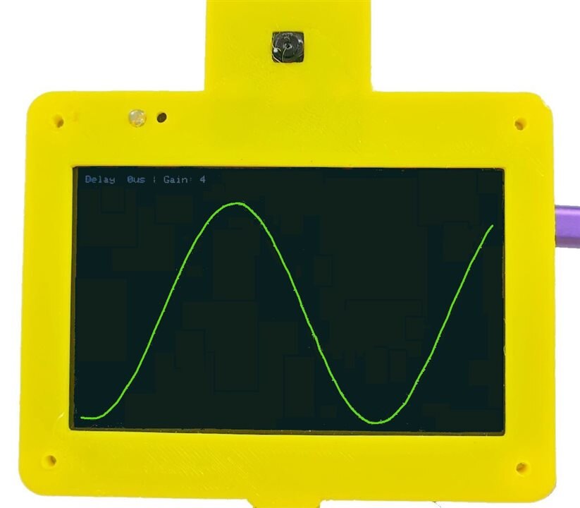
The video doesn't look as good as the in-person experience, but hopefully it came out well enough to get a feel for what it looks like in real life.
/*
  Giga Display Oscilloscope
  by Doug Wong 2025
  - Continuous plotting of ADC (A0) on 800x480 Landscape.
  - Scanline refresh (Erase old pixel -> Draw new pixel).
  - Touch Controls:
    1. Bottom (0-700px, H=50): Sets Delay (0-100us)
    2. Right (W=50, H=480): Sets Gain (0.1x - 1.0x)
    3. Leftt (W=50, H=480): Sets Trigger (0 - 480)
    Touch the screen to update signal trace - stop touching to freeze the trace
*/

#include "Arduino_GigaDisplay_GFX.h"
#include "Arduino_H7_Video.h"
#include "Arduino_GigaDisplayTouch.h"

GigaDisplay_GFX display;

// --- Configuration ---
#define SCREEN_WIDTH  800
#define SCREEN_HEIGHT 480
#define ADC_PIN       A0

// UI Dimensions
#define BOTTOM_TOUCH_WIDTH 700
#define BOTTOM_TOUCH_HEIGHT 50
#define RIGHT_TOUCH_WIDTH  50
#define RIGHT_TOUCH_HEIGHT 480

// Colors
#define COLOR_BG    0x0000 // Black
#define COLOR_TRACE 0x07E0 // Green
#define COLOR_TEXT  0xFFFF // White
#define COLOR_UI    0x3333 // Dark Grey (for UI guides)

// --- Objects ---
Arduino_H7_Video Display(800, 480, GigaDisplayShield);
Arduino_GigaDisplayTouch Touch;

// --- Global Variables ---
uint16_t signalBuffer[SCREEN_WIDTH]; // Stores Y-coordinates of the previous scan
int currentX = 0;
int rawADC;
int tADC;
int lastADC;

// Oscilloscope Settings
unsigned long sampleDelayMicros = 0; // 0 to 130 microseconds
float gain = 0.1;                    // 0.1 to 1.0
int gaini;
int trigger = 200;

// Helper to track previous touch state to avoid flickering UI updates
int lastTouchZoneDelay = -1;
int lastTouchZoneGain = -1;
uint8_t contacts;
GDTpoint_t points[5];

void setup() {
  pinMode(LED_BUILTIN, OUTPUT);     // Initialize the LED_BUILTIN pin as an output
  // Initialize Serial (Optional for debug)
  Serial.begin(115200);

  // Initialize Display
  Display.begin();
  display.begin();
  display.setRotation(1);
  display.fillScreen(COLOR_BG);

  // Initialize Touch
  Touch.begin();

  // Configure ADC
  analogReadResolution(12); // 0-4095
  pinMode(ADC_PIN, INPUT);

  // Initialize Buffer (Center screen initially)
  for (int i = 0; i < SCREEN_WIDTH; i++) {
    signalBuffer[i] = SCREEN_HEIGHT / 2;
  }

  // Draw UI Guidelines (Optional: Visual indicators for touch areas)
  gaini = gain * 10;
//  drawInterfaceGuides();
  updateStatsOnScreen();
}

void loop() {
  // 1. Handle Touch Input (Check strictly before sampling to adjust params)
  handleTouch();

//  tADC = analogRead(ADC_PIN);
//  if (tADC > lastADC && tADC > trigger) {
 for (int X = 0; X < SCREEN_WIDTH; X++) {

  // Perform Trace Update

  // 2. Capture New Sample
  rawADC = analogRead(ADC_PIN);

  // 3. Erase the pixel from the previous scan at this X position
  display.drawPixel(X, signalBuffer[X], COLOR_BG);

  // 4. Calculate Logic
  int newY = SCREEN_HEIGHT - round(rawADC * gain);

  // 5. Draw New Pixel
  display.drawPixel(X, newY, COLOR_TRACE);

  // 6. Update Buffer
  signalBuffer[X] = newY;

  // 7. Apply Sample Delay
  if (sampleDelayMicros > 0) {
    delayMicroseconds(sampleDelayMicros);
  }
 }
//}
//  lastADC = tADC;
//  display.fillRect(0, 20, 2, 2, COLOR_BG);     //need to isplay something for the drawPixel activity to be displayed
}

void handleTouch() {

  // Read touch points
  contacts = Touch.getTouchPoints(points);

  if (contacts > 0) {
    int ty = SCREEN_HEIGHT - points[0].x;
    int tx = points[0].y;

    // --- Check Bottom Area (Delay Control) ---
    // Area: x[0-700], y[430-480] (Bottom 50px)
    if (tx > 50 && tx < BOTTOM_TOUCH_WIDTH && ty > (SCREEN_HEIGHT - BOTTOM_TOUCH_HEIGHT)) {
      // 14 Zones, 50px wide each.
      int zone = (tx - 50) / 50;
      if (zone > 12) zone = 12;

      // Map zone 0-13 to 0-56 microseconds (step of 4)
      sampleDelayMicros = zone * 10;
    }

    // --- Check Right Area (Gain Control) ---
    // Area: x[750-800], y[0-480]
    else if (tx >= (SCREEN_WIDTH - RIGHT_TOUCH_WIDTH)) {
      // 12 Zones, 40px high each.
      int zone = (SCREEN_HEIGHT - ty) / 40;
      if (zone > 11) zone = 11;

      // Map zone 0-11 to Gain 0.1 - 1.0
      // We have 12 steps to cover range 0.9.
      // Step size approx 0.081.
      // Simple linear mapping: 0.1 + (zone / 11.0) * 0.9
      gain = 0.1 + ((float)zone / 11.0) * 0.9;
    }

        // --- Check Leftt Area (Trigger Control) ---
    // Area: x[0-50], y[0-480]
    else if (tx < (50)) {

      trigger = SCREEN_HEIGHT - points[0].x;
    }
      updateStatsOnScreen();
  }
}

// Draws visual markers so you know where to touch
void drawInterfaceGuides() {
    // Divider for Bottom Area
    display.drawLine(0, SCREEN_HEIGHT - BOTTOM_TOUCH_HEIGHT, BOTTOM_TOUCH_WIDTH, SCREEN_HEIGHT - BOTTOM_TOUCH_HEIGHT, COLOR_UI);
    // Ticks for Bottom Area
    for(int i=0; i<=14; i++) {
        display.drawLine(i*50, SCREEN_HEIGHT - BOTTOM_TOUCH_HEIGHT, i*50, SCREEN_HEIGHT, COLOR_UI);
    }

    // Divider for Right Area
    display.drawLine(SCREEN_WIDTH - RIGHT_TOUCH_WIDTH, 0, SCREEN_WIDTH - RIGHT_TOUCH_WIDTH, SCREEN_HEIGHT, COLOR_UI);
    // Ticks for Right Area
    for(int i=0; i<=12; i++) {
        display.drawLine(SCREEN_WIDTH - RIGHT_TOUCH_WIDTH, i*40, SCREEN_WIDTH, i*40, COLOR_UI);
    }
}

// Displays current settings in top left corner
void updateStatsOnScreen() {
    // Simple text overlay to show current settings
    // We draw a black box first to erase old text
    display.fillRect(0, 0, 300, 20, COLOR_BG);

    display.setCursor(0, 0);
    display.setTextSize(2);
    display.setTextColor(COLOR_UI);

    display.print("Delay: ");
    display.print(sampleDelayMicros);
    display.print("us | Gain: ");
    gaini = (1.1 - gain) * 10;
    display.print(gaini);
}
I had a blast road testing the Arduino Giga with its touch LCD. I was absolutely tickled at how easy it was to implement sophisticated applications using built-in hardware. That isn't to say everything went smoothly and quickly, but problems were mostly to do with me, not the support materials available.
The example code and libraries available from Arduino and online were a big help in developing applications that went a bit beyond what was available.
The feature set of the Giga platform is so extensive, I only just scratched the surface of what it can do. I didn't even get around to using the accelerometers on the LCD module. Actually I had planned to use them to lock the camera video to gravity, but since the camera is mounted to the display, the video is always upright, regardless of camera tilt. For some reason, it wasn't obvious to me until I saw it in action.
Another feature I didn't get to was Bluetooth low energy. My main computer and other Arduino modules do not do BLE, so I gave this one a pass. This road test blog is already too long, but it would be hard to cover this many features in a shorter review. Other things I didn't push into were the large number of I/O pins, the dual core architecture and the large memory. This review required lots of small programs, not one huge program - thankfully.
I did post individual blogs about each of the applications I explored, which may help them be searchable. If you want a little more detail, they are linked below.
In summary, this Giga plus LCD platform is the only platform with this many high-end microcontroller features. It isn't super cheap, but it is good value and it can handle pretty much any microcontroller task with ease. It is actually a full computer platform, with a complete user interface built-in. I could see it being used as a stand-alone system that is used to develop its own software - maybe with a Python IDE. Presumably a USB keyboard could be plugged in to avoid having to use the touch screen as a keyboard.
I really like the fact that the Giga has tons of I/O and I especially like that many peripheral interfaces have their own standard connector, such as camera, LCD, audio and even antenna. The USB host functionality adds a whole world of possibilities and the capacitive touch screen provides a very potent user interface. However, if I had to choose the one feature that surprised or impressed me the most out of all the superlative features, I would say the speed with which it can load and display a 768 kbyte full color image was a total surprise, but a very useful and pleasant one.
I have to say it is both a super powerful and a super fun platform and I am certain I will find lots of uses for it. I am so happy and grateful that I got to participate in this road test. Thanks e14 and Arduino.
Touch Screen and USB memory demo
GIGA display of an Arducam video camera


