


Intro
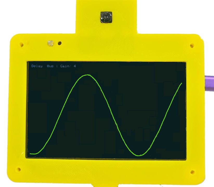
The last demo I want to show in this road test is an oscilloscope application. The Arduino Giga with its display has the infrastructure to implement an oscilloscope function so I wanted to include a quick demo of this in action.. This demo simply captures samples from the ADC and displays them on screen.
This program uses the touch screen to control the time scale, the amplitude and the trigger.
GIGA Scope Video
Giga Scope Sketch
/*
  Giga Display Oscilloscope
  by Doug Wong 2025
  - Continuous plotting of ADC (A0) on 800x480 Landscape.
  - Scanline refresh (Erase old pixel -> Draw new pixel).
  - Touch Controls:
    1. Bottom (0-700px, H=50): Sets Delay (0-100us)
    2. Right (W=50, H=480): Sets Gain (0.1x - 1.0x)
    3. Leftt (W=50, H=480): Sets Trigger (0 - 480)
    Touch the screen to update signal trace - stop touching to freeze the trace
*/

#include "Arduino_GigaDisplay_GFX.h"
#include "Arduino_H7_Video.h"
#include "Arduino_GigaDisplayTouch.h"

GigaDisplay_GFX display;

// --- Configuration ---
#define SCREEN_WIDTH  800
#define SCREEN_HEIGHT 480
#define ADC_PIN       A0

// UI Dimensions
#define BOTTOM_TOUCH_WIDTH 700
#define BOTTOM_TOUCH_HEIGHT 50
#define RIGHT_TOUCH_WIDTH  50
#define RIGHT_TOUCH_HEIGHT 480

// Colors
#define COLOR_BG    0x0000 // Black
#define COLOR_TRACE 0x07E0 // Green
#define COLOR_TEXT  0xFFFF // White
#define COLOR_UI    0x3333 // Dark Grey (for UI guides)

// --- Objects ---
Arduino_H7_Video Display(800, 480, GigaDisplayShield);
Arduino_GigaDisplayTouch Touch;

// --- Global Variables ---
uint16_t signalBuffer[SCREEN_WIDTH]; // Stores Y-coordinates of the previous scan
int currentX = 0;
int rawADC;
int tADC;
int lastADC;

// Oscilloscope Settings
unsigned long sampleDelayMicros = 0; // 0 to 130 microseconds
float gain = 0.1;                    // 0.1 to 1.0
int gaini;
int trigger = 200;

// Helper to track previous touch state to avoid flickering UI updates
int lastTouchZoneDelay = -1;
int lastTouchZoneGain = -1;
uint8_t contacts;
GDTpoint_t points[5];

void setup() {
  pinMode(LED_BUILTIN, OUTPUT);     // Initialize the LED_BUILTIN pin as an output
  // Initialize Serial (Optional for debug)
  Serial.begin(115200);

  // Initialize Display
  Display.begin();
  display.begin();
  display.setRotation(1);
  display.fillScreen(COLOR_BG);

  // Initialize Touch
  Touch.begin();

  // Configure ADC
  analogReadResolution(12); // 0-4095
  pinMode(ADC_PIN, INPUT);

  // Initialize Buffer (Center screen initially)
  for (int i = 0; i < SCREEN_WIDTH; i++) {
    signalBuffer[i] = SCREEN_HEIGHT / 2;
  }

  // Draw UI Guidelines (Optional: Visual indicators for touch areas)
  gaini = gain * 10;
//  drawInterfaceGuides();
  updateStatsOnScreen();
}

void loop() {
  // 1. Handle Touch Input (Check strictly before sampling to adjust params)
  handleTouch();

//  tADC = analogRead(ADC_PIN);
//  if (tADC > lastADC && tADC > trigger) {
 for (int X = 0; X < SCREEN_WIDTH; X++) {

  // Perform Trace Update

  // 2. Capture New Sample
  rawADC = analogRead(ADC_PIN);

  // 3. Erase the pixel from the previous scan at this X position
  display.drawPixel(X, signalBuffer[X], COLOR_BG);

  // 4. Calculate Logic
  int newY = SCREEN_HEIGHT - round(rawADC * gain);

  // 5. Draw New Pixel
  display.drawPixel(X, newY, COLOR_TRACE);

  // 6. Update Buffer
  signalBuffer[X] = newY;

  // 7. Apply Sample Delay
  if (sampleDelayMicros > 0) {
    delayMicroseconds(sampleDelayMicros);
  }
 }
//}
//  lastADC = tADC;
//  display.fillRect(0, 20, 2, 2, COLOR_BG);     //need to isplay something for the drawPixel activity to be displayed
}

void handleTouch() {

  // Read touch points
  contacts = Touch.getTouchPoints(points);

  if (contacts > 0) {
    int ty = SCREEN_HEIGHT - points[0].x;
    int tx = points[0].y;

    // --- Check Bottom Area (Delay Control) ---
    // Area: x[0-700], y[430-480] (Bottom 50px)
    if (tx > 50 && tx < BOTTOM_TOUCH_WIDTH && ty > (SCREEN_HEIGHT - BOTTOM_TOUCH_HEIGHT)) {
      // 14 Zones, 50px wide each.
      int zone = (tx - 50) / 50;
      if (zone > 12) zone = 12;

      // Map zone 0-13 to 0-56 microseconds (step of 4)
      sampleDelayMicros = zone * 10;
    }

    // --- Check Right Area (Gain Control) ---
    // Area: x[750-800], y[0-480]
    else if (tx >= (SCREEN_WIDTH - RIGHT_TOUCH_WIDTH)) {
      // 12 Zones, 40px high each.
      int zone = (SCREEN_HEIGHT - ty) / 40;
      if (zone > 11) zone = 11;

      // Map zone 0-11 to Gain 0.1 - 1.0
      // We have 12 steps to cover range 0.9.
      // Step size approx 0.081.
      // Simple linear mapping: 0.1 + (zone / 11.0) * 0.9
      gain = 0.1 + ((float)zone / 11.0) * 0.9;
    }

        // --- Check Leftt Area (Trigger Control) ---
    // Area: x[0-50], y[0-480]
    else if (tx < (50)) {

      trigger = SCREEN_HEIGHT - points[0].x;
    }
      updateStatsOnScreen();
  }
}

// Draws visual markers so you know where to touch
void drawInterfaceGuides() {
    // Divider for Bottom Area
    display.drawLine(0, SCREEN_HEIGHT - BOTTOM_TOUCH_HEIGHT, BOTTOM_TOUCH_WIDTH, SCREEN_HEIGHT - BOTTOM_TOUCH_HEIGHT, COLOR_UI);
    // Ticks for Bottom Area
    for(int i=0; i<=14; i++) {
        display.drawLine(i*50, SCREEN_HEIGHT - BOTTOM_TOUCH_HEIGHT, i*50, SCREEN_HEIGHT, COLOR_UI);
    }

    // Divider for Right Area
    display.drawLine(SCREEN_WIDTH - RIGHT_TOUCH_WIDTH, 0, SCREEN_WIDTH - RIGHT_TOUCH_WIDTH, SCREEN_HEIGHT, COLOR_UI);
    // Ticks for Right Area
    for(int i=0; i<=12; i++) {
        display.drawLine(SCREEN_WIDTH - RIGHT_TOUCH_WIDTH, i*40, SCREEN_WIDTH, i*40, COLOR_UI);
    }
}

// Displays current settings in top left corner
void updateStatsOnScreen() {
    // Simple text overlay to show current settings
    // We draw a black box first to erase old text
    display.fillRect(0, 0, 300, 20, COLOR_BG);

    display.setCursor(0, 0);
    display.setTextSize(2);
    display.setTextColor(COLOR_UI);

    display.print("Delay: ");
    display.print(sampleDelayMicros);
    display.print("us | Gain: ");
    gaini = (1.1 - gain) * 10;
    display.print(gaini);
}
The scope function is very screen-centric. Since the display is 800x480, every trace has exactly 800 samples, which are also stored in a buffer so that the pixel at each of the 800 positions may be erased before being replaced by a new sample. This way, the whole screen does not need to be redrawn, just the pixel that is changing.
The ADC is being run with 12 bit resolution (4096 counts full scale), which is almost 10 times more that the 480 pixel LCD can display, 480 counts of a possible 4096 times 3.3 volts (the ADC max) gives 0.387 Volts at 1 ADC count per pixel. This means we want a maximum gain to correspond to 0.387 Volts providing 480 counts. At the minimum gain we want 4096 counts to correspond to 480 pixels. The touch slider on the right of the screen is actually set up to go from a gain of 0.1 to a gain of 1 times the ADC reading, but this is displayed as a gain of 1 to 10, just to keep the display simple.
The time scale is also based on Giga performance. The loop to capture an ADC sample, delete the old sample and display the new one has a minimum period. This period can be extended from 0 microseconds to 120 microseconds using the invisible slider at the bottom of the screen. I tried graticule marks on the screen, but got rid of them because the aesthetic cost outweighed the marginal benefit.
The trigger slider is on the left. It simply picks which vertical pixel will be used as the trace trigger.
Discussion
I liked that the Giga and its display are fast enough to make a low frequency scope function, although my implementation leaves a lot to be desired. I learned a few things about how hard it would be to make a siick scope, which is always good, and I am happy that this sketch at least provides some proof that a scope function is possible.
In looking at the video, I probably should have chosen a white scope trace instead of green - it would have been s bit brighter. It looks great to the human eye - just the camera had a hard time showing the trace.
Links:
Touch Screen and USB memory demo
GIGA display of an Arducam video camera

