element14 Community
element14 Community
    Register Log In
  • Site
  • Search
  • Log In Register
  • About Us
  • Community Hub
    Community Hub
    • What's New on element14
    • Feedback and Support
    • Benefits of Membership
    • Personal Blogs
    • Members Area
    • Achievement Levels
  • Learn
    Learn
    • Ask an Expert
    • eBooks
    • element14 presents
    • Learning Center
    • Tech Spotlight
    • STEM Academy
    • Webinars, Training and Events
    • Learning Groups
  • Technologies
    Technologies
    • 3D Printing
    • FPGA
    • Industrial Automation
    • Internet of Things
    • Power & Energy
    • Sensors
    • Technology Groups
  • Challenges & Projects
    Challenges & Projects
    • Design Challenges
    • element14 presents Projects
    • Project14
    • Arduino Projects
    • Raspberry Pi Projects
    • Project Groups
  • Products
    Products
    • Arduino
    • Avnet Boards Community
    • Dev Tools
    • Manufacturers
    • Multicomp Pro
    • Product Groups
    • Raspberry Pi
    • RoadTests & Reviews
  • Store
    Store
    • Visit Your Store
    • Choose another store...
      • Europe
      •  Austria (German)
      •  Belgium (Dutch, French)
      •  Bulgaria (Bulgarian)
      •  Czech Republic (Czech)
      •  Denmark (Danish)
      •  Estonia (Estonian)
      •  Finland (Finnish)
      •  France (French)
      •  Germany (German)
      •  Hungary (Hungarian)
      •  Ireland
      •  Israel
      •  Italy (Italian)
      •  Latvia (Latvian)
      •  
      •  Lithuania (Lithuanian)
      •  Netherlands (Dutch)
      •  Norway (Norwegian)
      •  Poland (Polish)
      •  Portugal (Portuguese)
      •  Romania (Romanian)
      •  Russia (Russian)
      •  Slovakia (Slovak)
      •  Slovenia (Slovenian)
      •  Spain (Spanish)
      •  Sweden (Swedish)
      •  Switzerland(German, French)
      •  Turkey (Turkish)
      •  United Kingdom
      • Asia Pacific
      •  Australia
      •  China
      •  Hong Kong
      •  India
      •  Korea (Korean)
      •  Malaysia
      •  New Zealand
      •  Philippines
      •  Singapore
      •  Taiwan
      •  Thailand (Thai)
      • Americas
      •  Brazil (Portuguese)
      •  Canada
      •  Mexico (Spanish)
      •  United States
      Can't find the country/region you're looking for? Visit our export site or find a local distributor.
  • Translate
  • Profile
  • Settings
Embedded and Microcontrollers
  • Technologies
  • More
Embedded and Microcontrollers
Blog MAX32660 Evaluation Kit - part 2: Mod the PCB for Power Measurement
  • Blog
  • Forum
  • Documents
  • Quiz
  • Polls
  • Files
  • Members
  • Mentions
  • Sub-Groups
  • Tags
  • More
  • Cancel
  • New
Join Embedded and Microcontrollers to participate - click to join for free!
  • Share
  • More
  • Cancel
Group Actions
  • Group RSS
  • More
  • Cancel
Engagement
  • Author Author: Jan Cumps
  • Date Created: 14 Dec 2018 6:14 PM Date Created
  • Views 821 views
  • Likes 2 likes
  • Comments 3 comments
  • RoadTest
  • max32660
  • maxim
  • road_test
Related
Recommended

MAX32660 Evaluation Kit - part 2: Mod the PCB for Power Measurement

Jan Cumps
Jan Cumps
14 Dec 2018

I'm road testing the  Ultra-Low Power Arm Cortex-M4 Darwin MCU EVM.

In this blog post I modify the PCB to isolate the power going to the MAX32660.

image


Where to Measure the Current Consumtion


Measuring the voltage is easy. You can do that on the upper right breakout pin.

To measure the current, you could use the TARGET VDD jumper on the debuger / programmer side, and use a low Burden current meter instead of the jumper.

This will work, but there are a few (low current) consumers on the debug circuit.

image


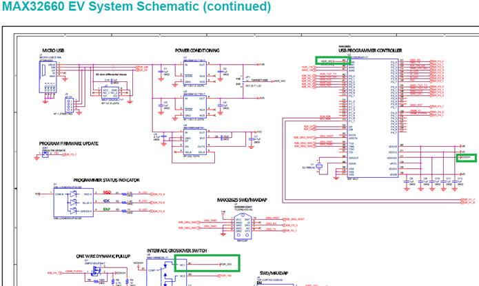
To rule those out in the power measurements, I chose to get the signal further downstream, where only the controller and peripherals use power.


image


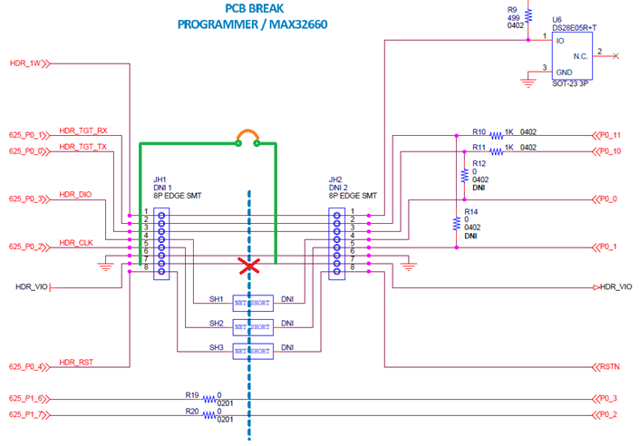
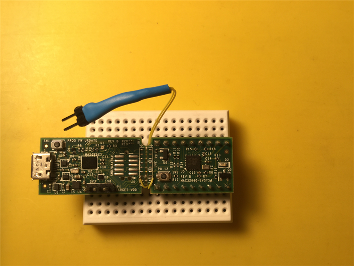
The way to be able to measure the current is to break the existing PCB trace and replace it by a jumper that can either be shortcut, or where you can insert a current meter.

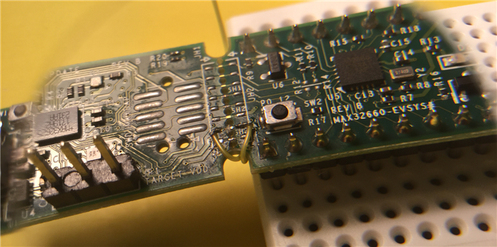
I soldered a wire on the positive supply line at both sides of the mouse bites in the middle of the PCB.

After checking that all was soldered correctly, I cut the copper trace for the power on the breakout mouse bites in the middle of the board.

Then I soldered pin headers at the end of the two wires, protected by heat shrink.

The two wires are hot glued on the PCB bottom side for strain relief.


image


When I put a little jumper over the header pins, the board works as before.


image


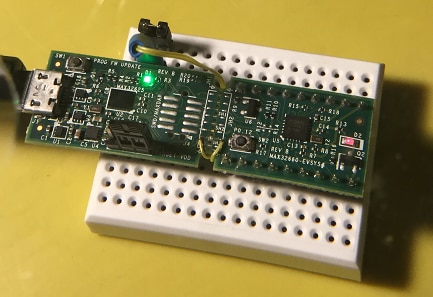
When I want to measure current, I can remove the jumper and put a sensitive, low Burden meter in between.


image


I will use this together with the Low Power example from Maxim. That project can cycle the controller through the different modes by pressing the button on the board.

That is going to be my next blog post ...


part 1: IDE install and Build First Example
part 2: Mod the PCB for Power Measurement
part 3: Power Measurement
part 4a: Low Power Sensor design - Barometer Hardware
part 4b: Low Power Sensor design - Barometer i2c and Init
part 4c: Low Power Sensor design - Barometer, Not Yet Power Optimised
MAX32660 Evaluation Kit - part 5: FreeRTOS Example
side note A: C++ Eclipse Project
side note B: Create a Release Configuration
  • Sign in to reply

Top Comments

  • Jan Cumps
    Jan Cumps over 6 years ago +2
    First measurements, using two different multimeters, 1.8 V Running in ACTIVE mode 6.72 mA All unused RAMs placed in LIGHT SLEEP mode 6.72 mA All unused RAMs shutdown 6.71 mA Entering SLEEP mode 2.73 mA…
  • DAB
    DAB over 6 years ago +2
    Good update Jan. DAB
  • Jan Cumps
    Jan Cumps over 6 years ago in reply to Jan Cumps +1
    For my own reference: 1.8 V measured with µCurrent in 1 mV/mA mode console off button off RTC, 10 s / mode
Parents
  • Jan Cumps
    Jan Cumps over 6 years ago

    First measurements, using two different multimeters, 1.8 V


    Running in ACTIVE mode                         6.72 mA
    All unused RAMs placed in LIGHT SLEEP mode     6.72 mA
    All unused RAMs shutdown                       6.71 mA
    Entering SLEEP mode                            2.73 mA
    Entering DEEPSLEEP mode                        3.57 mA
    Entering BACKUP mode                           0.21 mA


    For some reason, DEEPSLEEP seems to pull more current then SLEEP.

    This is measured without debugger, and with enabeling USB/UART0 clock.


    It would be interesting to see other tester's measurements.


    With 3.3 V supply:

    7,57
    7,56
    7,55
    3,48
    5,21
    0,74


    A trace of the current, switching between modes every 5 seconds, with 1.8 V

    image

    • Cancel
    • Vote Up +2 Vote Down
    • Sign in to reply
    • More
    • Cancel
  • Jan Cumps
    Jan Cumps over 6 years ago in reply to Jan Cumps

    For my own reference:

    1.8 V

    measured with µCurrent in 1 mV/mA mode

    console off

    button off

    RTC, 10 s / mode


    image

    • Cancel
    • Vote Up +1 Vote Down
    • Sign in to reply
    • More
    • Cancel
Comment
  • Jan Cumps
    Jan Cumps over 6 years ago in reply to Jan Cumps

    For my own reference:

    1.8 V

    measured with µCurrent in 1 mV/mA mode

    console off

    button off

    RTC, 10 s / mode


    image

    • Cancel
    • Vote Up +1 Vote Down
    • Sign in to reply
    • More
    • Cancel
Children
No Data
element14 Community

element14 is the first online community specifically for engineers. Connect with your peers and get expert answers to your questions.

  • Members
  • Learn
  • Technologies
  • Challenges & Projects
  • Products
  • Store
  • About Us
  • Feedback & Support
  • FAQs
  • Terms of Use
  • Privacy Policy
  • Legal and Copyright Notices
  • Sitemap
  • Cookies

An Avnet Company © 2025 Premier Farnell Limited. All Rights Reserved.

Premier Farnell Ltd, registered in England and Wales (no 00876412), registered office: Farnell House, Forge Lane, Leeds LS12 2NE.

ICP 备案号 10220084.

Follow element14

  • X
  • Facebook
  • linkedin
  • YouTube