element14 Community
element14 Community
    Register Log In
  • Site
  • Search
  • Log In Register
  • Community Hub
    Community Hub
    • What's New on element14
    • Feedback and Support
    • Benefits of Membership
    • Personal Blogs
    • Members Area
    • Achievement Levels
  • Learn
    Learn
    • Ask an Expert
    • eBooks
    • element14 presents
    • Learning Center
    • Tech Spotlight
    • STEM Academy
    • Webinars, Training and Events
    • Learning Groups
  • Technologies
    Technologies
    • 3D Printing
    • FPGA
    • Industrial Automation
    • Internet of Things
    • Power & Energy
    • Sensors
    • Technology Groups
  • Challenges & Projects
    Challenges & Projects
    • Design Challenges
    • element14 presents Projects
    • Project14
    • Arduino Projects
    • Raspberry Pi Projects
    • Project Groups
  • Products
    Products
    • Arduino
    • Avnet Boards Community
    • Dev Tools
    • Manufacturers
    • Multicomp Pro
    • Product Groups
    • Raspberry Pi
    • RoadTests & Reviews
  • About Us
  • Store
    Store
    • Visit Your Store
    • Choose another store...
      • Europe
      •  Austria (German)
      •  Belgium (Dutch, French)
      •  Bulgaria (Bulgarian)
      •  Czech Republic (Czech)
      •  Denmark (Danish)
      •  Estonia (Estonian)
      •  Finland (Finnish)
      •  France (French)
      •  Germany (German)
      •  Hungary (Hungarian)
      •  Ireland
      •  Israel
      •  Italy (Italian)
      •  Latvia (Latvian)
      •  
      •  Lithuania (Lithuanian)
      •  Netherlands (Dutch)
      •  Norway (Norwegian)
      •  Poland (Polish)
      •  Portugal (Portuguese)
      •  Romania (Romanian)
      •  Russia (Russian)
      •  Slovakia (Slovak)
      •  Slovenia (Slovenian)
      •  Spain (Spanish)
      •  Sweden (Swedish)
      •  Switzerland(German, French)
      •  Turkey (Turkish)
      •  United Kingdom
      • Asia Pacific
      •  Australia
      •  China
      •  Hong Kong
      •  India
      •  Korea (Korean)
      •  Malaysia
      •  New Zealand
      •  Philippines
      •  Singapore
      •  Taiwan
      •  Thailand (Thai)
      • Americas
      •  Brazil (Portuguese)
      •  Canada
      •  Mexico (Spanish)
      •  United States
      Can't find the country/region you're looking for? Visit our export site or find a local distributor.
  • Translate
  • Profile
  • Settings
FPGA
  • Technologies
  • More
FPGA
Blog 7 Ways to Leave Your Spartan-6 Experiments with the FPGA polarimeter.
  • Blog
  • Forum
  • Documents
  • Quiz
  • Events
  • Polls
  • Files
  • Members
  • Mentions
  • Sub-Groups
  • Tags
  • More
  • Cancel
  • New
Join FPGA to participate - click to join for free!
  • Share
  • More
  • Cancel
Group Actions
  • Group RSS
  • More
  • Cancel
Engagement
  • Author Author: jure
  • Date Created: 27 Jul 2022 9:41 PM Date Created
  • Views 9009 views
  • Likes 10 likes
  • Comments 4 comments
  • 7 Ways to Leave Your Spartan-6
  • experimenting
  • fpga
  • spartan-7
  • Spartan_Migration
Related
Recommended

7 Ways to Leave Your Spartan-6 Experiments with the FPGA polarimeter.

jure
jure
27 Jul 2022

To conclude with the FPGA polarimeter for the 7 Ways to Leave Your Spartan-6 contest, I have run some experiments, where I explored some optical phenomena in everyday objects. This will hopefully serve as a simple demonstration of what a polarimeter can be used for.

In previous blog posts (first post, second post) we have explored how I have constructed a working polarimeter. I have not had the option to test it in a real lab but was able to build 3 experiments from mostly household items. Since I didn't have any optical components and mounting devices, I had to use whatever I had at hand. Hence I used Lego bricks to assemble the mechanical parts of the experiments. Hence I would recommend reading everything with a big grain of salt. I did try to perform experiments as repeatably as I could, so they would illustrate something.

A note on reading the results

Most of the readers probably never heard of Stokes parameters. In this short section, I want to give some information about what these parameters represent. But before looking at that, let's just remember how light polarization works. We can describe light with two perpendicular oscillating electric fields. If they are in sync, the polarization is circular. If they are out of sync the polarization is elliptical. If the phases of the fields are 90° apart, we then have circularly polarized light.

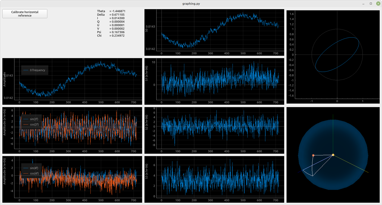
Onto the Stokes parameters. The S0 parameter tells us the intensity of light (proportional to the power). Both S1 and S2 parameters tell us the angle of polarization as well as the "amount of linear polarization". Finally, the S3 parameter tells us about the "ellipticity of the light". So if S1 or S2 is much greater than the S3, the polarization is linear or close to linear. If S3 is greater than both the S1 or S2, then the polarization is elliptical.

I have also added Chi and Psi info in the screenshots. Psi is simply the angle of the central axis of the polarization. The tangent of phi describes the ratio between the major and minor axis in the polarization ellipse (refer to this image). If Chi is zero the polarization is linear if chi is close to pi/2 or -pi/2 the polarization is close to circular.

For each experiment, I will tell you what to look at and give a brief description of what it tells us.

1. Experiment: Sugar as a circular polarizer

imageAn interesting property of sugar is, that some molecules can polarize light. For example, dextrose causes right-hand circular polarization. This is commonly used to measure the content of sugar. Since we have a device that can measure every possible polarization, we can explore this phenomenon.

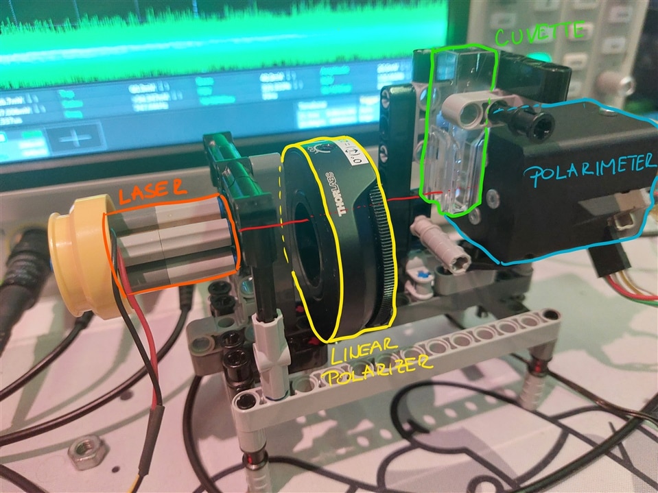
First I have constructed a simple construct that holds a cuvette, adjustable polarizer and a laser diode. The light from the diode is polarized, after which it passes through a cuvette. Finally, the transmitted light is measured. 

First I had to find a reference for the measurement. I did this by filling the cuvette with plain tap water and measuring the light. After that, I emptied the cuvette and refilled it with water with dissolved sugar.

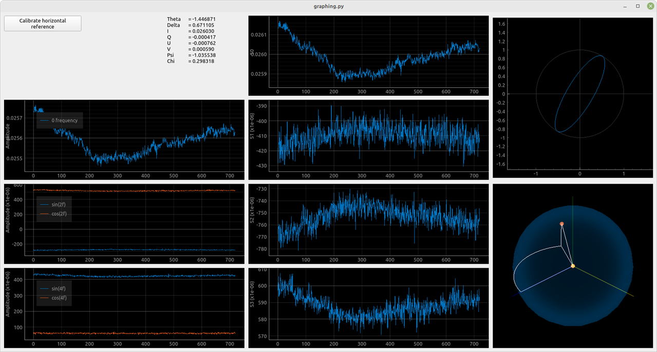
{gallery}Sugar polarization measurement

image

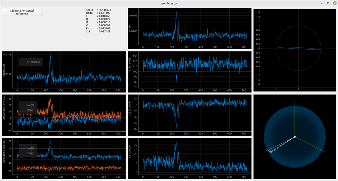
Reference measurement of the water-filled cuvette. Transmitted light has a slightly elliptical polarization, which is probably due to the plastic, from which the cuvette is made.

image

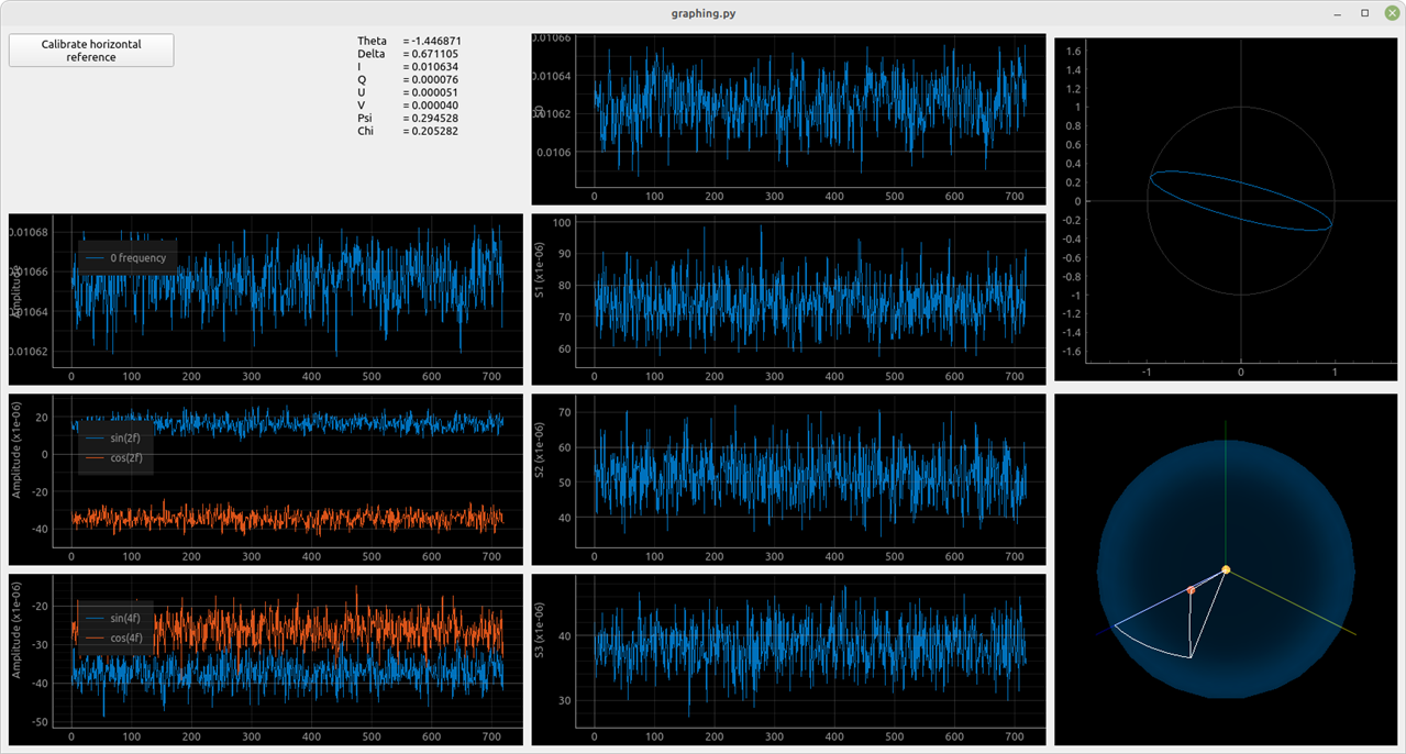
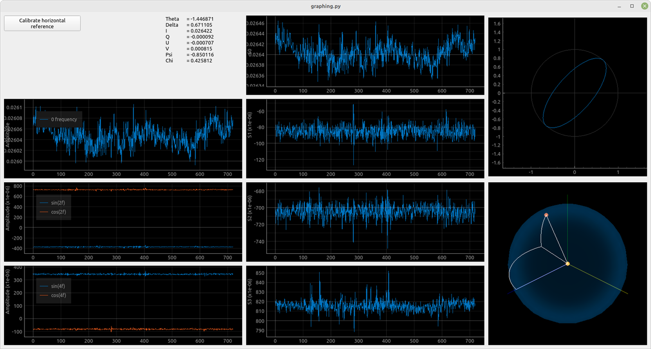
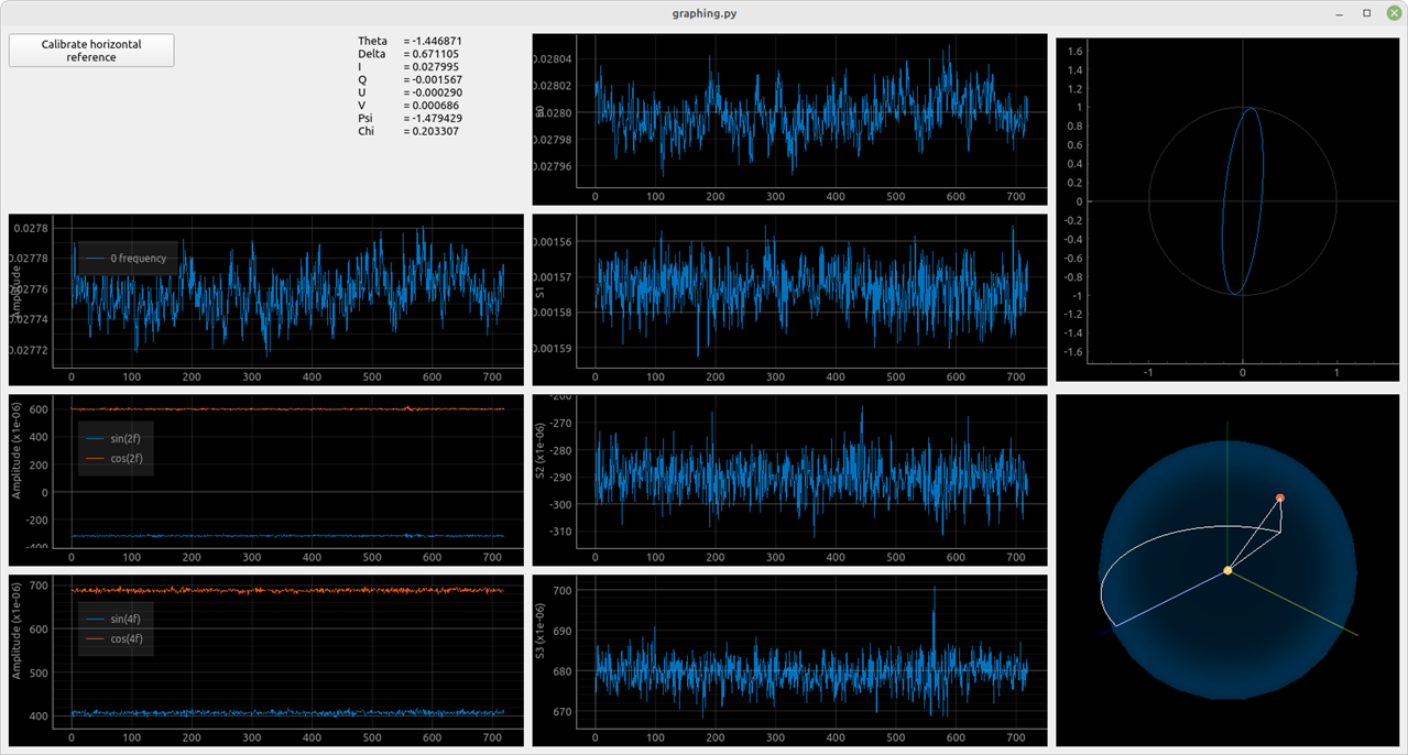
Measurement of a cuvette filled with water with dissolved sugar. The light is much more elliptically polarized.

As we can see from the images (the ellipse in the upper right corner), we can see that the sugar caused the polarization of light to become much more elliptical. This is as expected as the ellipticity of transmitted light is proportional to the concentration of sugar.

2. Experiment: Optical fibre and polarization.

image

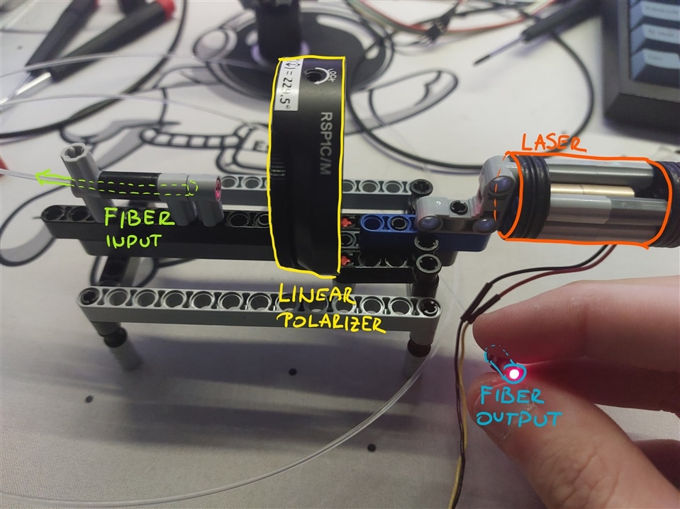
For the second experiment, I wanted to see whether a cheap plastic optical fibre could retain polarization to some degree. For this, I used about 0.5m of 1.6mm diameter plastic fibre. I used a laser which was shining light through an adjustable linear polarizer. The light was then coupled into the fibre. The output side of the fibre was mounted onto a polarimeter. I then spun the polarizer to 180° and observed the results.

image

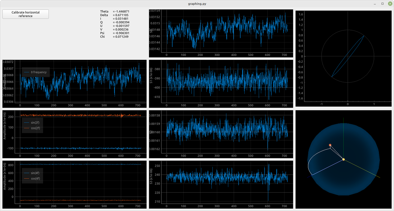
From the image above, we can see that this fibre doesn't preserve any polarization since  S1, S2, and S3 (graphs in the middle column) show just the noise (both the ellipse plot and the sphere plot were jumping around due to noise). The intensity is due to the polarization of the laser light.

3. Experiment: Brewsters effect

Lastly, we're going to take a look at how reflection changes the polarization properties of light. The experiment is quite simple. I simply measured the reflected light at different angles. I used a mirror that I had lying around. The laser Light used in the beginning is linearly polarized, yet the angle is not known.

I used the row of Lego bricks in the middle as a scale, for which I then measured the angles Phi.

{gallery}Brewsters effect experiment

image

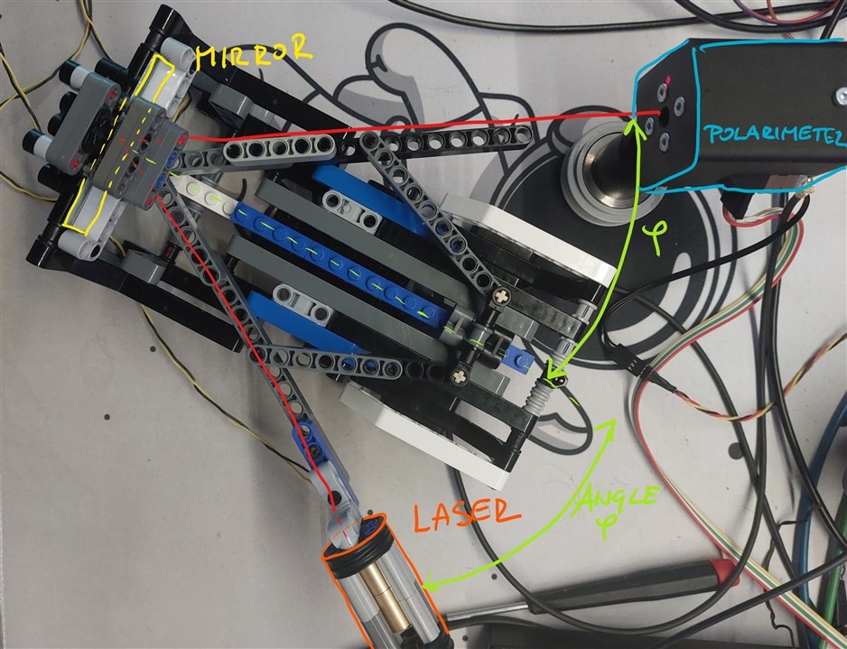
Setup from above (misalignment in the laser spot is due to perspective as well as a slight angle of the assembly)

image

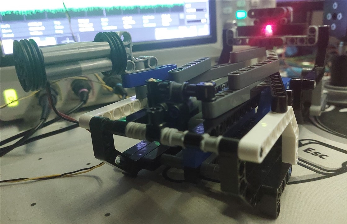
Setup as seen along the optical path of the reflected light.

{gallery}Reflection polarization measurements

image

Measurement of reflected light at 63°

image

Measurement of reflected light at 54°

image

Measurement of reflected light at 45°

image

Measurement of reflected light at 35°

image

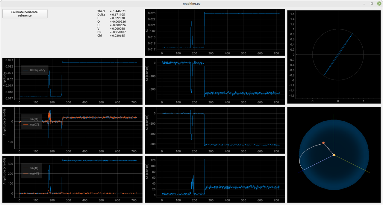
Measurement of reflected light at 20°

image

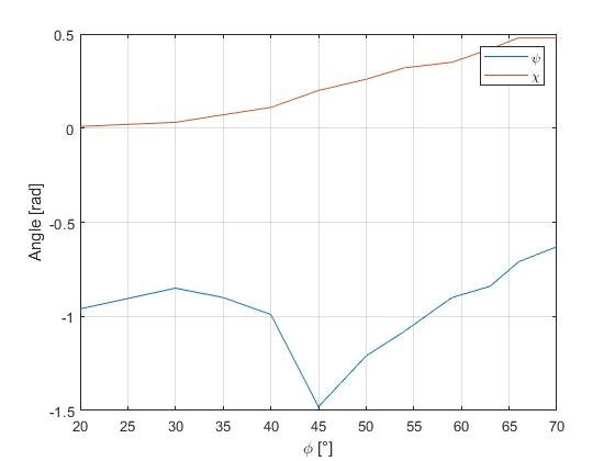
We can see in the images that the light becomes more and more elliptical with increasing angles (look at the ellipse plot in the top right). We can see this better in the following plot.

As we can see from the plot and the screenshot, the polarisation angle (angle Psi) has some angular dependence. This is due to the Brewster effect. Similarly, we can see that Chi has some angular dependence as well. This is because some phase difference between the electric field components is obtained when the light is reflected. 

Observed problems

During the experiments I noticed some problems with the device, hence I did not look at all the details with every experiment. All of the experiments were done with extremely weak light since I do not want to damage my ADC (I don't have any spare). Second I have observed that I have a non-negligible amount of noise in DC component measurement. I will have to look at resolving this since it causes issues when working with weak light sources. This prevents causes a few issues when I looking at parameters which are obtained through multiplication or division of the S0 parameter.

Conclusion

Hopefully, I have presented some interesting phenomena in everyday items. I also hope that I have successfully Illustrated the functionality of a polarimeter. If you have any questions or comments I will gladly answer/respond.

  • Sign in to reply

Top Comments

  • javagoza
    javagoza over 3 years ago +1
    Your experiment is very interesting. Have you used the laser that you mentioned in your previous blog, the OPV330? I have never worked with a laser, any safety recommendations and how to use it without…
  • jure
    jure over 3 years ago in reply to javagoza +1
    Thank you. No, I have used a red laser diode (~650nm). The main reason is that I already had the laser assembly with the optics inside and was unable to find suitable optics for the OPV (the optical paths…
Parents
  • javagoza
    javagoza over 3 years ago

    Your experiment is very interesting. Have you used the laser that you mentioned in your previous blog, the OPV330? I have never worked with a laser, any safety recommendations and how to use it without damaging it or damaging yourself?

    • Cancel
    • Vote Up +1 Vote Down
    • Sign in to reply
    • More
    • Cancel
  • jure
    jure over 3 years ago in reply to javagoza

    Thank you. No, I have used a red laser diode (~650nm). The main reason is that I already had the laser assembly with the optics inside and was unable to find suitable optics for the OPV (the optical paths in the experiments were quite long and I was unable to focus it well enough). Secondly, 850nm is on the border of the visible range. When focused the laser dot could barely be seen. It was much easier to align everything with red laser light.


    Second I would suggest getting a constant current driver (like with most LEDs it is better to control using current). You can use a decent power supply (make sure it can be adjusted in the correct range e.g. mA). There are also some nice modules (I used this https://www.thorlabs.com/thorproduct.cfm?partnumber=MLD203CLNE with their eval board). Work using the datasheet of the laser and read them thoroughly.


    For safety recommendations, I would suggest looking at laser classes and what they mean. I used lasers with ~10mW of power, which are mainly harmless. Keep in mind that power density is a very important factor. As such powerful but unfocused laser can be less damaging than a lower-power laser but very focused.

    It's a good practice to set everything up at a different height than your head. This can prevent any beams from reaching your eyes. When working with visible light you can use a piece of cardboard to track the beam. If working with invisible light you'll have to use something like this https://www.thorlabs.com/thorproduct.cfm?partnumber=VRC2. In general, avoid using any shiny objects (e.g. screwdrivers) in the optical setup to avoid any accidental reflections. If using high-power lasers (<0.5A) you'll need beam dumps to "terminate" the laser (black heatsink will work in most cases). This will prevent burnt holes and damage (i have seen the result of this).

    • Cancel
    • Vote Up +1 Vote Down
    • Sign in to reply
    • More
    • Cancel
  • javagoza
    javagoza over 3 years ago in reply to jure

    Thank you very much for your extensive and detailed answer. It seems to me that until my children grow up and I have a place to do these experiments safely, I will have to content myself with reading what others are capable of doing.

    • Cancel
    • Vote Up 0 Vote Down
    • Sign in to reply
    • More
    • Cancel
Comment
  • javagoza
    javagoza over 3 years ago in reply to jure

    Thank you very much for your extensive and detailed answer. It seems to me that until my children grow up and I have a place to do these experiments safely, I will have to content myself with reading what others are capable of doing.

    • Cancel
    • Vote Up 0 Vote Down
    • Sign in to reply
    • More
    • Cancel
Children
  • jure
    jure over 3 years ago in reply to javagoza

    No problem. I think experimenting with optics is similar to electronics. When working with low voltage/power devices there is not much to worry about, but most people are still careful when touching and connecting things.

    For children, I think that experimenting with optics is some of the best experiences in terms of science/physics. And it is still a very valuable process since optical components require some careful handling to keep them clean and prevent damage. A relatively easy solution is to connect all of the lasers on a common mains power cable with a switch. Turn on the experiment only when everyone is ready and in their place. Also, use protection glasses.

    • Cancel
    • Vote Up 0 Vote Down
    • Sign in to reply
    • More
    • Cancel
element14 Community

element14 is the first online community specifically for engineers. Connect with your peers and get expert answers to your questions.

  • Members
  • Learn
  • Technologies
  • Challenges & Projects
  • Products
  • Store
  • About Us
  • Feedback & Support
  • FAQs
  • Terms of Use
  • Privacy Policy
  • Legal and Copyright Notices
  • Sitemap
  • Cookies

An Avnet Company © 2025 Premier Farnell Limited. All Rights Reserved.

Premier Farnell Ltd, registered in England and Wales (no 00876412), registered office: Farnell House, Forge Lane, Leeds LS12 2NE.

ICP 备案号 10220084.

Follow element14

  • X
  • Facebook
  • linkedin
  • YouTube