


In this blog post, we will add HDMI video output to our Arty S7. We will build upon the basic microblaze system that we constructed in the previous blog post.
The first thing you might be wondering is how to get a physical HDMI output from the Arty-S7, since there is no HDMI ports on the board. Well, this is one of those situations that really shows the flexibility and power of FPGAs. More on this later. Let's get the FPGA design up first.
We start with the basic hello microblaze design that we created in the previous blog post.
On a high-level, we will add:
- RGB-to-DVI IP -> We will use a Digilent IP for this (we will need to edit the IP in Vivado's IP packager to add Spartan-7 as supported device family and repackage the IP)
- Video Test Pattern Generato (TPG)r -> Xilinx makes available this IP free-of-cost
- AXI4-Stream to Video Out IP -> To convert the TPG output from AXIStream to RGB format with Video Sync, valid signals
- Video Timing Controller -> Xilinx IP, available free-of-cost. Generates the video timing signals (HSync, VSync, DataValid) for a certain video format
- Clocking wizard to generate the pixel clock as well as a 5x serial clock needed for HDMI output. This will use the "ui_clk" clock output from the MIG (Memory Interface Generator) as the clock source
Open the block design from the hello microblaze project in Vivado. First of all, add Clocking a "Clocking WIzard" IP to the block design:

We will be using the output clock of MIG to run our subsequent design's clocks
Connect clk_in1 (input) of this Clocking Wizard block to the "ui_clk" output of MIG
Connect reset (input) of this Clocking Wizard block to the "ui_clk_sync_rst" output from the MIG.
Now, double-click the Clocking Wizard IP block to open and set outputs as following. We are setting up clocks for 640x480, 60fps output. We go for a lower resolution fist to get the whole system up before trying to push for higher performance.

Click OK to save and close the dialog box.
Next, we add "Video Timing Controller" IP. Once added to block design, double click to edit.
On the first tab we un-check the "Enable Detection" option, since we will only use it to generate video timing signals. We also reduct the maximum resolution values to save some resources.

We dont' change the rest of settings as those we will configure over the AXI4Lite interface from microblaze code. Click OK to close.
We will run the IP from the HDMI pixel clock, so connect the "clk" input to "clk_hdmi" output of Clocking Wizard IP

Next we add a "Video Test Pattern Generator" IP from the IP catalog and double click it to customize it as following:

Click OK to close. For clocking this IP, since the output is in AXIStream, we connect "ap_clk" input to the "ui_clk" clock ouput from MIG7 IP.
Since the output of the Test Pattern Generator is in AXIStream format, we need to convert this into the native video format (pixel data, sync signals), so we add a "AXI4-Stream to Video Out" IP from the IP catalog. Customize it as following:

We use "Master" timing mode as we want this IP to be the clocking master for the Video Timing Controller. For that effect, also connect the "vtg_ce" output of this IP to the "gen_clken" input fo the Video Timing Controller IP added earlier.

To clock the "AXI4-Stream to Video Out" IP's "aclk" input, we use the "ui_clk" output from the MIG7. This sets the clock for the AXIStream side.
And the "video_io_out_clk" input we can connect to the "clk_hdmi" of clocking wizard. This sets the clock for the Native video output from this IP.
Also, connect the Video Input and Timing inputs as following:

Next we add a HDMI encoder. For this, I am using the "RGB to DVI Video Encoder (Source)" IP from Digilent. I have already setup my Vivado to include the IPs from Digilent. (Let me know in comments if you are not able to do that). Also note that this IP is not enabled for Spartan7 family, so I had to edit the IP in IP packager to add Spartan7 as supported family. It's a very simple process, but I plan to write about this process in a separate blog post so that this one doesn't get too long. Please leave a comment if you need help with this.
After adding the IP, customize it as following. Since we already have a clock and 5x clock for HDMI, we don't need to generate the 5x clock internally.

Click OK to close.
Connect the PixelClk and Serial Clk of the HDMI IP to the "clk_hdmi" and "clk_hdmi5x" from the clocking wizard.

Also connect the Video Path as shown here:

Right click on the TMDS port and select "Make external" to tell Vivado we will be connecting this externally

Once the external port is created, select it and change the name to "hdmi_tx_0" from the property editor. This is something we don't NEED to do. But I renamed it to this since I will be using this name to assign pin constraints later.

At this point, we can run "connection Automation" to complete the remaining connections automatically

We connect the "locked" output of the clocking wizard as the reset input for the HDMI encoder. This way, only once the clock is locked, the HDMI IP will come out of reset

Optionally (and recommended), we can also add one or more "ILA" or "System ILA" IPs to monitor the critical signals in the design later.
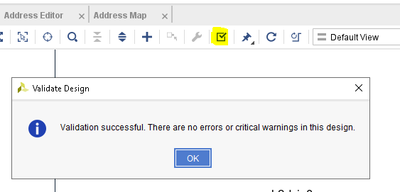
At this point, we can validate the design to make sure there are no errors.
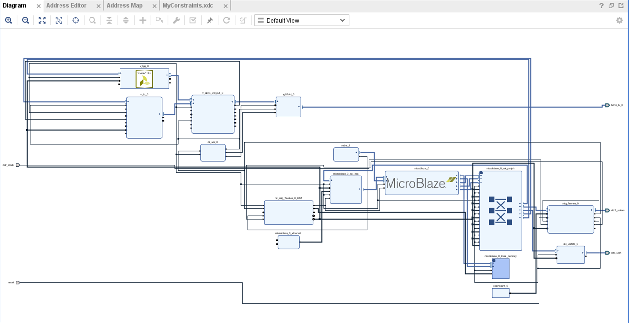
Here's our final block design
Next, we need to tell Vivado where the external ports are connected. Note that anything that we used from the "Boards" tab will automatically have it's constraints added by Vivado and we don't need to bother with those. In this case, we added our own HDMI transmitter, so we need to tell Vivado which pins we're going to use for this. We do this by adding a "Constraints" file to our project. Vivado will read this in addition to the board's own constraint file.
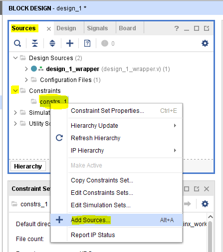
Click Sources -> Constraints -> constrs_1 (right-click) -> Add Sources
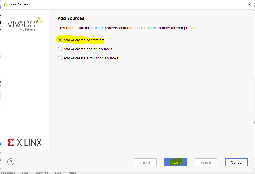
Add an empty Contraints file by following these steps:
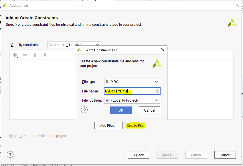
Once the newly created file opens, we add the following lines to it and save it:
set_property -dict {PACKAGE_PIN M18 IOSTANDARD TMDS_33} [get_ports hdmi_tx_0_clk_p]
set_property -dict {PACKAGE_PIN M16 IOSTANDARD TMDS_33} [get_ports {hdmi_tx_0_data_p[2]}]
set_property -dict {PACKAGE_PIN M14 IOSTANDARD TMDS_33} [get_ports {hdmi_tx_0_data_p[1]}]
set_property -dict {PACKAGE_PIN L17 IOSTANDARD TMDS_33} [get_ports {hdmi_tx_0_data_p[0]}]
Basically we are assigning the Pins for the TMDS pairs for HDMI (HDMI uses TMDS signalling). For differential pairs, we only need to specify the positive pin for a pair. The negative pin is automatically assigned. I will talk more about the pin assignment in the next blog post when we add a physical HDMI port to our board.
Anyway, now we have done all that we needed to do on the Vivado side. All that's left is to generate the Bitstream, and export it.
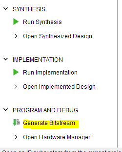
Once this process completes successfuly, we can re-export the updated bitstream:
File -> Export -> Export Hardware.
Since we already exported the previous "Hello microblaze" to the same folder, it will ask if it can overwrite the previous bitstream. Answer YES.
After this, we can switch to Vitis IDE
Click Tools -> Launch VITIS IDE
Once VITIS opens, we edit our previously created helloworld.c to the following code:
/*
 * helloworld.c: simple test application
 *
 * This application configures UART to baud rate 9600. *
 */

#include <stdio.h>
#include "platform.h"
#include "xil_printf.h"

#include "xparameters.h"
#include "xvtc.h"
#include "xv_tpg.h"

#define XVTC_DEVICE_ID			XPAR_VTC_0_DEVICE_ID

XVtc	VtcInst;		/**< Instance of the VTC core. */

typedef struct {
	char label[64]; /* Label describing the resolution */
	u32 width; /*Width of the active video frame*/
	u32 height; /*Height of the active video frame*/
	u32 hps; /*Start time of Horizontal sync pulse, in pixel clocks (active width + H. front porch)*/
	u32 hpe; /*End time of Horizontal sync pulse, in pixel clocks (active width + H. front porch + H. sync width)*/
	u32 hmax; /*Total number of pixel clocks per line (active width + H. front porch + H. sync width + H. back porch) */
	u32 hpol; /*hsync pulse polarity*/
	u32 vps; /*Start time of Vertical sync pulse, in lines (active height + V. front porch)*/
	u32 vpe; /*End time of Vertical sync pulse, in lines (active height + V. front porch + V. sync width)*/
	u32 vmax; /*Total number of lines per frame (active height + V. front porch + V. sync width + V. back porch) */
	u32 vpol; /*vsync pulse polarity*/
	double freq; /*Pixel Clock frequency*/
} VideoMode;

static const VideoMode VMODE_640x480 =
{
	.label = "640x480@60Hz",
	.width = 640,
	.height = 480,
	.hps = 656,//640+16
	.hpe = 752,//
	.hmax = 799,
	.hpol = 0,
	.vps = 490,
	.vpe = 492,
	.vmax = 524,
	.vpol = 0,
	.freq = 25.0
};


VideoMode vMode;


int configureStartVTC()
{
	int Status;
	XVtc_Config *Config;
	XVtc_Signal *SignalCfgPtr;

	XVtc_Timing vtcTiming;
	XVtc_SourceSelect SourceSelect;


	/* Initialize the VTC driver so that it's ready to use look up
	 * configuration in the config table, then initialize it.
	 */
	Config = XVtc_LookupConfig(XVTC_DEVICE_ID);

	/* Checking Config variable */
	if (NULL == Config) {
		return (XST_FAILURE);
	}

	Status = XVtc_CfgInitialize(&VtcInst, Config, Config->BaseAddress);

	/* Checking status */
	if (Status != (XST_SUCCESS)) {
		return (XST_FAILURE);
	}

	/* Perform a self-test  */
	Status = XVtc_SelfTest(&VtcInst);

	/* Checking status */
	if (Status != (XST_SUCCESS)) {
		return (XST_FAILURE);
	}


	vMode = VMODE_640x480;

	/*
	 * Configure the vtc core with the display mode timing parameters
	 */
	vtcTiming.HActiveVideo = vMode.width; /**< Horizontal Active Video Size */
	vtcTiming.HFrontPorch = vMode.hps - vMode.width; /**< Horizontal Front Porch Size */
	vtcTiming.HSyncWidth = vMode.hpe - vMode.hps; /**< Horizontal Sync Width */
	vtcTiming.HBackPorch = vMode.hmax - vMode.hpe + 1; /**< Horizontal Back Porch Size */
	vtcTiming.HSyncPolarity = vMode.hpol; /**< Horizontal Sync Polarity */
	vtcTiming.VActiveVideo = vMode.height; /**< Vertical Active Video Size */
	vtcTiming.V0FrontPorch = vMode.vps - vMode.height; /**< Vertical Front Porch Size */
	vtcTiming.V0SyncWidth = vMode.vpe - vMode.vps; /**< Vertical Sync Width */
	vtcTiming.V0BackPorch = vMode.vmax - vMode.vpe + 1;
	; /**< Horizontal Back Porch Size */
	vtcTiming.V1FrontPorch = vMode.vps - vMode.height; /**< Vertical Front Porch Size */
	vtcTiming.V1SyncWidth = vMode.vpe - vMode.vps; /**< Vertical Sync Width */
	vtcTiming.V1BackPorch = vMode.vmax - vMode.vpe + 1;
	; /**< Horizontal Back Porch Size */
	vtcTiming.VSyncPolarity = vMode.vpol; /**< Vertical Sync Polarity */
	vtcTiming.Interlaced = 0; /**< Interlaced / Progressive video */

	/* Setup the VTC Source Select config structure. */
	/* 1=Generator registers are source */
	/* 0=Detector registers are source */
	memset((void *) &SourceSelect, 0, sizeof(SourceSelect));
	SourceSelect.VBlankPolSrc = 1;
	SourceSelect.VSyncPolSrc = 1;
	SourceSelect.HBlankPolSrc = 1;
	SourceSelect.HSyncPolSrc = 1;
	SourceSelect.ActiveVideoPolSrc = 1;
	SourceSelect.ActiveChromaPolSrc = 1;
	SourceSelect.VChromaSrc = 1;
	SourceSelect.VActiveSrc = 1;
	SourceSelect.VBackPorchSrc = 1;
	SourceSelect.VSyncSrc = 1;
	SourceSelect.VFrontPorchSrc = 1;
	SourceSelect.VTotalSrc = 1;
	SourceSelect.HActiveSrc = 1;
	SourceSelect.HBackPorchSrc = 1;
	SourceSelect.HSyncSrc = 1;
	SourceSelect.HFrontPorchSrc = 1;
	SourceSelect.HTotalSrc = 1;

	Status = XVtc_SelfTest(&VtcInst);

	XVtc_RegUpdateEnable(&VtcInst);
	XVtc_SetGeneratorTiming(&VtcInst, &vtcTiming);
	XVtc_SetSource(&VtcInst, &SourceSelect);

	/*
	 * Enable VTC core
	 */
	XVtc_EnableGenerator(&VtcInst);


	return (XST_SUCCESS);
}


int configureStartTPG()
{
	int Status;

	XV_tpg * tpgInst;
	XV_tpg_Config *tpg_Config;

	tpg_Config = XV_tpg_LookupConfig(XPAR_V_TPG_0_DEVICE_ID);
	if (tpg_Config == NULL)
	{
		xil_printf("ERR:: TPG device not found\r\n");
		return (XST_DEVICE_NOT_FOUND);
	}

	Status = XV_tpg_CfgInitialize(tpgInst, tpg_Config, tpg_Config->BaseAddress);
	if (Status != XST_SUCCESS)
	{
		xil_printf("ERR:: TPG Initialization failed %d\r\n", Status);
		return (XST_FAILURE);
	}

	// Must RESET the Tpg since it's a HLS IP (This must be done through GPIO on IP reset port)
	// RESET HERE!

	XV_tpg_Set_height(tpgInst, vMode.height);
	XV_tpg_Set_width(tpgInst, vMode.width);
	XV_tpg_Set_colorFormat(tpgInst, 0);
	XV_tpg_Set_bckgndId(tpgInst, XTPG_BKGND_COLOR_BARS);//XTPG_BKGND_RAINBOW_COLOR //XTPG_BKGND_CHECKER_BOARD //XTPG_BKGND_HV_RAMP//XTPG_BKGND_H_RAMP//XTPG_BKGND_RAINBOW_COLOR
	XV_tpg_Set_ovrlayId(tpgInst, 0);
	XV_tpg_Set_enableInput(tpgInst, 0);	// Enable (1) or disable (0) the video pass through
	XV_tpg_Set_passthruStartX(tpgInst, 0);
	XV_tpg_Set_passthruStartY(tpgInst, 0);
	XV_tpg_Set_passthruEndX(tpgInst, vMode.width);
	XV_tpg_Set_passthruEndY(tpgInst, vMode.height);
	XV_tpg_WriteReg(tpg_Config->BaseAddress, XV_TPG_CTRL_ADDR_AP_CTRL,	0x81); //start, auto-restart

	return XST_SUCCESS;
}

int main()
{
    init_platform();

    print("Hello World\n\r");

    configureStartVTC();
    configureStartTPG();

    print("Successfully ran Hello World application");

    while(1)
    {
    	;
    }
    cleanup_platform();
    return 0;
}
The main() function at the bottom of the code file gives an overview of the code. It does the following things:
1. Configure and Start Video Timing Controller at 640x480 resolution.
2. We configure and start the Video Test Pattern Generator.
The code in the functions themselves have more details of what is done to achieve the above. Please leave a comment if anything is not clear.
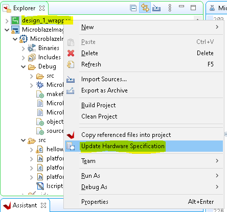
Before we build the application code, we need to update the hardware specification based on the hardware we just exported (because we previously used the same project for the "hello microblaze"). We will also need to repeat this step if we generate and export the bitstream again in future.
Right-click design_1_wrapper (the Platform Project), then select "Update Hardware Specification".
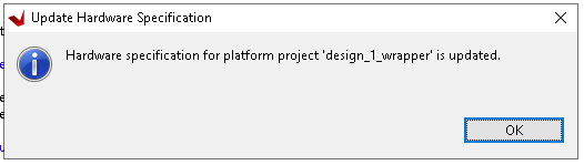
Wait for successful completion message:
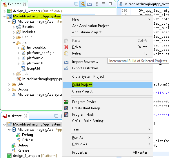
Now, we can rebuild the project with the newly added code. Right-click the application project and click "Build Project"
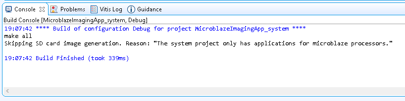
The project build status can be confirmed in the console output.
Now the last thing that needs to be done is to build the special PMOD-to-HDMI cable that we need, and then test it. I will address this in the next blog post.


