Hello everyone, I'll be writing a step-by-step tutorial on building a basic line follower robot with the Arty S7.

This project requires the following components:
Hardware
- IR proximity sensors x 5
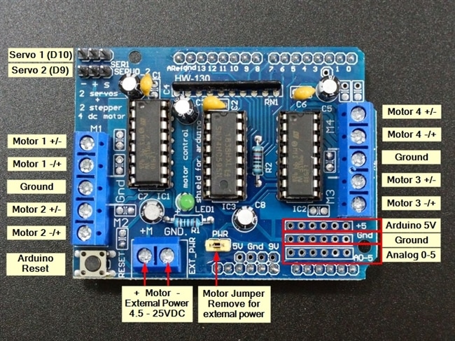
- Motor driver shield x 1
- 60 RPM BO motors x 2
- Ball caster x 1
- 3.7V 2600mAh Li-ion battery x 2
Software
- Vivado® Design Suite 2019.2


Arty S7 Features
- Expansion Connectors: 4 Pmod connectors, Arduino/chipKIT Shield connector
- Interaction and Sensory Devices: 4 Switches, 4 Buttons, 1 Board Reset Button, 1 FPGA Reset Button, 4 Green LEDs, 2 RGB LEDs
- System Connectivity: USB-UART Bridge
- Power: Powered from USB or any 7V-15V source
- USB-JTAG Programming circuitry (USB Micro cable required, NOT INCLUDED).
- 100 MHz External Clock
- 128 Mbits Quad-SPI Flash
- 256 MB DDR3L with a 16-bit bus @ 650 MHz
- Programmable over JTAG and Quad-SPI Flash
- On-chip analog-to-digital converter (XADC)
- Internal clock speeds exceeding 450MHz;
- DSP Slices: 120
- Clock Management Tiles: 5
- Block RAM (Kbits): 2,700
- Flip-flops: 65,200
- Slices: 8,150
- Logic Cells: 52,160
- 1 MSPS On-chip ADC
- FPGA Part: XC7S50-CSGA324
Algorithm
The BO motors are wired to the Motor driver shield. The shield and the Arty S7 share the power from a 2S Li-ion battery. The digital signals are fed as the inputs to the motor driver. The Line sensors or the IR proximity sensors are adjusted to detect the black line. When sensors on the left are HIGH, the robot moves towards the right and when sensors on the right are HIGH, the robot moves to the left thus it catches the line.

Hardware Issue:

Read the next blog to set up Vivado 2019.2 on a windows 10 machine and run a Demo program on Arty S7.
Thanks for reading!

