


Polyphase FIRs
The half-band FIR is just one particular case of a larger class of FIR filter implementations called polyphase structures. The basic idea is to split the sum of products we need to compute for every filter output sample into multiple sub-sums or phases, using the associativity property of addition. From a mathematical point of view, this would be expressed by the following formula:
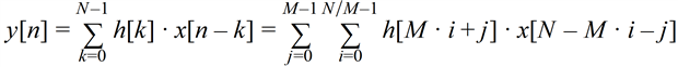
What this means is that we have M partial sums which are computed separately and then added together to produce the final result. Each partial sum accesses input samples and filter coefficients in a modulo M way.
This of course provides no savings whatsoever, the number of operations is exactly the same. Also, the half-band FIR we have seen earlier is the case where M=2 and half of the filter coefficients are zero, except for the center one, which is 0.5. But as the half-band single rate FIR becomes interesting when used as a 2x interpolator or decimator, the single rate polyphase FIR with M phases is ideal for interpolation or decimation by a factor of M.
These are multi-rate FIRs, filters where the input and output sample rates are not equal. In the case of the M-Polyphase interpolator the output sample rate is M times higher than the input sample rate. Similarly, for the decimator the output sample rate is M times smaller than the input sample rates.
The way the interpolator works is by raising the input sample rate by a factor of M through the insertion of M-1 zero samples between the normal input samples. This will introduce M-1 undesirable copies of the input spectrum and the role of the single rate prototype FIR is to attenuate them while leaving the base band spectral image untouched. This means that this prototype FIR needs to have a very flat pass band, high attenuation in the stop band and a very sharp transition band, with all three factors leading to a large filter order N. It is not uncommon for these prototype filters to have hundreds, even thousands of taps. Fortunately, since only one out of every M input sample is non-zero, most of these partial products do not need to be calculated and the computation load is reduced by a factor of M.
The decimator benefits from a similar reduction when we consider that we do not have to compute the M-1 output samples, which will be dropped anyway through the decimation process. The computational reduction in the number of multiplications and additions is the same, a factor of M.
Our hardware implementation will run at a particular system clock rate and we have two options here, we can choose it to be equal to the lower sample rate, the input one for the interpolator and the output one for the decimator, or the other way around.
The first case is simpler. Such an interpolator accepts one input sample every clock and produces M output samples per clock. It consists of M completely independent single rate FIRs of order N/M, each one with its own set of coefficients. The M FIRs have their inputs tied together and produce M output samples every clock. Such an architecture is useful when you need to produce a signal with a sample rate much higher than the maximum possible clock rate in the FPGA fabric. For example, typical FPGA implementations can run at speeds in the 400 MHz to 800 MHz range, depending on FPGA family and speed grade, but you may need to interface to digital-to-analog converters with rates in the 1 Gsps to 8 Gsps range. A polyphase interpolator can be used as part of the up-conversion process and bridge the gap between the two rates. There is nothing new about this type of implementation, it is just M instances of a single rate N/M tap FIR of the type we have seen in Post 5.
The decimator is very similar. Once again we have M separate single rate FIRs of order N/M, each one consuming one of the M input samples that come in every clock. We then add together the outputs of the M single rate FIRs, and this produces the single sample per clock output of our decimator. Like in the case of the interpolator, this is useful for doing the down conversion required to reduce the sample rates of a multi Gbps DAC to a rate that can be handled by the FPGA fabric. Also, there is nothing new about this filter architecture either, it is simply M single rate FIRs running in parallel. The final M-input post adder can be implemented in the fabric as an adder tree, or if increased latency is not an issue, we could save those fabric resources by cascading the adder chains of the M FIRs and delaying the inputs to each one accordingly to account for the increase in latency. The first option will have lower latency, especially if a transpose architecture is used for the individual phases, the second one will use fewer fabric resources. If an adder tree is chosen, this post from the previous season of the Art of FPGA Design shows the most efficient way to build one, using 3-input Carry Save Adders.
The second case is more interesting. Here the higher sample rate, the interpolator output or the decimator input, is equal to the system clock rate and the lower sample rate is M times slower. By running the multipliers and adders at the highest possible frequency, we can take advantage of that using a time-sharing technique and further reduce the utilization by a factor of M.
In the next two posts we will look at the use of this type of polyphase FIRs for efficient interpolation and decimation with rates other than 2x.
Back to the top: The Art of FPGA Design Season 2
