element14 Community
element14 Community
    Register Log In
  • Site
  • Search
  • Log In Register
  • Community Hub
    Community Hub
    • What's New on element14
    • Feedback and Support
    • Benefits of Membership
    • Personal Blogs
    • Members Area
    • Achievement Levels
  • Learn
    Learn
    • Ask an Expert
    • eBooks
    • element14 presents
    • Learning Center
    • Tech Spotlight
    • STEM Academy
    • Webinars, Training and Events
    • Learning Groups
  • Technologies
    Technologies
    • 3D Printing
    • FPGA
    • Industrial Automation
    • Internet of Things
    • Power & Energy
    • Sensors
    • Technology Groups
  • Challenges & Projects
    Challenges & Projects
    • Design Challenges
    • element14 presents Projects
    • Project14
    • Arduino Projects
    • Raspberry Pi Projects
    • Project Groups
  • Products
    Products
    • Arduino
    • Avnet Boards Community
    • Dev Tools
    • Manufacturers
    • Multicomp Pro
    • Product Groups
    • Raspberry Pi
    • RoadTests & Reviews
  • About Us
  • Store
    Store
    • Visit Your Store
    • Choose another store...
      • Europe
      •  Austria (German)
      •  Belgium (Dutch, French)
      •  Bulgaria (Bulgarian)
      •  Czech Republic (Czech)
      •  Denmark (Danish)
      •  Estonia (Estonian)
      •  Finland (Finnish)
      •  France (French)
      •  Germany (German)
      •  Hungary (Hungarian)
      •  Ireland
      •  Israel
      •  Italy (Italian)
      •  Latvia (Latvian)
      •  
      •  Lithuania (Lithuanian)
      •  Netherlands (Dutch)
      •  Norway (Norwegian)
      •  Poland (Polish)
      •  Portugal (Portuguese)
      •  Romania (Romanian)
      •  Russia (Russian)
      •  Slovakia (Slovak)
      •  Slovenia (Slovenian)
      •  Spain (Spanish)
      •  Sweden (Swedish)
      •  Switzerland(German, French)
      •  Turkey (Turkish)
      •  United Kingdom
      • Asia Pacific
      •  Australia
      •  China
      •  Hong Kong
      •  India
      •  Korea (Korean)
      •  Malaysia
      •  New Zealand
      •  Philippines
      •  Singapore
      •  Taiwan
      •  Thailand (Thai)
      • Americas
      •  Brazil (Portuguese)
      •  Canada
      •  Mexico (Spanish)
      •  United States
      Can't find the country/region you're looking for? Visit our export site or find a local distributor.
  • Translate
  • Profile
  • Settings
FPGA
  • Technologies
  • More
FPGA
Forum Vivado and Zynq: TRI-STATE help
  • Blog
  • Forum
  • Documents
  • Quiz
  • Events
  • Polls
  • Files
  • Members
  • Mentions
  • Sub-Groups
  • Tags
  • More
  • Cancel
  • New
Join FPGA to participate - click to join for free!
Actions
  • Share
  • More
  • Cancel
Forum Thread Details
  • State Not Answered
  • +1 person also asked this people also asked this
  • Replies 31 replies
  • Subscribers 551 subscribers
  • Views 14968 views
  • Users 0 members are here
  • zynq
  • vivado
Related

Vivado and Zynq: TRI-STATE help

Jan Cumps
Jan Cumps over 3 years ago

I'm trying to write i2c code for Zynq, in VHDL.
I have difficulties creating a TRI-STATE pin.

The output logic should be: the pin is either pulled down to 0, or open-collector.
I have a pull-up resistor between that pin and VCC (3.3 V).
I'm expecting that if I write '0', it is low. When I write 'Z', it's open collector and pulled high by my pullup.
But in my design, the pin stays low. 0.62 V.

I thought, from reading up, that I should be done by:

  • defining the pin as INOUT
  • when you want to drive it low, assign '0'.
  • when you want to drive it open collector, assign 'Z'.
  • put an external pullup between pin and VCC

I created a testbed that puts the pin in "Z' mode, except when reset is asserted (via an external button).
In my testbed I also added a test pin, that I attach to an LED, that is high when the reset is asserted.
I connected a multimeter to the output.

The LED behaves as expected. It lights up when I assert the reset.
But the tri-state pin stays low, whether I write '0' or 'Z' to it. 

entity tristate_test is
    Port ( 
    reset_n: in std_logic;
    reset_out: out std_logic;
    tristate_pin : inout std_logic);
end tristate_test;

architecture Behavioral of tristate_test is

begin

reset_active: process (reset_n) is

begin
  if (reset_n = '0') then
    tristate_pin <= '0';
    reset_out <= '1';
  else
    tristate_pin <= 'Z';
    reset_out <= '0';
  end if;
end process reset_active;

end Behavioral;

Here is how I set the constraint:

image

set_property PACKAGE_PIN Y18 [get_ports tristate_pin_0]
set_property IOSTANDARD LVCMOS33 [get_ports tristate_pin_0]
set_property DRIVE 12 [get_ports tristate_pin_0]

Schema:

image

PMOD A pin 1 is PACKAGE_PIN Y18

What am I doing wrong?

  • Sign in to reply
  • Cancel

Top Replies

  • jc2048
    jc2048 over 3 years ago +4
    It might be a problem with hierarchy with the drag-and-drop stuff. An answer to this support question suggests that you need to set the synthesis to flatten the hierachy so that the tristate-ness can propagate…
  • jc2048
    jc2048 over 3 years ago in reply to bhfletcher +4
    Once you understand that the block-based design is an entity that could be used as part of a larger, more traditional design, the issue with the top-level wrapper becomes clearer. If the user is just using…
  • rachaelp
    rachaelp over 3 years ago +3
    Hi Jan, Just create the tristate in an assignment and not in a process. Not sure why what you have isn't working, have you looked at the schematic for what it's creating in Vivado? I guess maybe it's…
  • jc2048
    0 jc2048 over 3 years ago in reply to Jan Cumps

    "I tried pins with name_T, name_I, name_O"

    What did the schematic view show when you did that? Was there still just an OBUF attached to name_O? Did it do anything with the other two?

    • Cancel
    • Vote Up 0 Vote Down
    • Sign in to reply
    • Verify Answer
    • Cancel
  • Jan Cumps
    0 Jan Cumps over 3 years ago in reply to jc2048

    When I generated the wrapper - the moment where I was expecting magic to happen -I get errors for unconnected pins.

    • Cancel
    • Vote Up 0 Vote Down
    • Sign in to reply
    • Verify Answer
    • Cancel
  • jc2048
    0 jc2048 over 3 years ago in reply to Jan Cumps

    What does your tristate_test code in the block look like now? Can you show it to us?

    • Cancel
    • Vote Up 0 Vote Down
    • Sign in to reply
    • Verify Answer
    • Cancel
  • Jan Cumps
    0 Jan Cumps over 3 years ago in reply to jc2048

    The IP code  - one of the many incarnations. I tried different combinations, directions, with and without process:

    library IEEE;
    use IEEE.STD_LOGIC_1164.ALL;
    
    entity tristate_test is
        Port ( 
        reset_n: in std_logic;
        reset_out: out std_logic;
        tri_T : out std_logic;
        tri_I : in std_logic;    
        tri_O : out std_logic);
    end tristate_test;
    
    architecture Behavioral of tristate_test is
    
    begin
    
    reset_active: process (reset_n) is
    
    begin
    null;
    end process reset_active;
    
     
    reset_out <= '1' when reset_n = '0' else '0';
    tri_O <= 'Z' when reset_n = '0' else '0';
    tri_T <= '1' when reset_n = '0' else '0';
    
    end Behavioral;

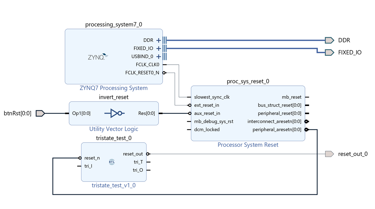
    The block design - I deliberately do not make ports external or assign a pin to them, because the manual says they need to be unconnected and not external

    image

    The wrapper code and the error message generated while wrapping:

    image

    --Copyright 1986-2020 Xilinx, Inc. All Rights Reserved.
    ----------------------------------------------------------------------------------
    --Tool Version: Vivado v.2020.2 (win64) Build 3064766 Wed Nov 18 09:12:45 MST 2020
    --Date        : Wed Feb  9 11:15:06 2022
    --Host        : paradise3 running 64-bit major release  (build 9200)
    --Command     : generate_target design_1_wrapper.bd
    --Design      : design_1_wrapper
    --Purpose     : IP block netlist
    ----------------------------------------------------------------------------------
    library IEEE;
    use IEEE.STD_LOGIC_1164.ALL;
    library UNISIM;
    use UNISIM.VCOMPONENTS.ALL;
    entity design_1_wrapper is
      port (
        DDR_addr : inout STD_LOGIC_VECTOR ( 14 downto 0 );
        DDR_ba : inout STD_LOGIC_VECTOR ( 2 downto 0 );
        DDR_cas_n : inout STD_LOGIC;
        DDR_ck_n : inout STD_LOGIC;
        DDR_ck_p : inout STD_LOGIC;
        DDR_cke : inout STD_LOGIC;
        DDR_cs_n : inout STD_LOGIC;
        DDR_dm : inout STD_LOGIC_VECTOR ( 3 downto 0 );
        DDR_dq : inout STD_LOGIC_VECTOR ( 31 downto 0 );
        DDR_dqs_n : inout STD_LOGIC_VECTOR ( 3 downto 0 );
        DDR_dqs_p : inout STD_LOGIC_VECTOR ( 3 downto 0 );
        DDR_odt : inout STD_LOGIC;
        DDR_ras_n : inout STD_LOGIC;
        DDR_reset_n : inout STD_LOGIC;
        DDR_we_n : inout STD_LOGIC;
        FIXED_IO_ddr_vrn : inout STD_LOGIC;
        FIXED_IO_ddr_vrp : inout STD_LOGIC;
        FIXED_IO_mio : inout STD_LOGIC_VECTOR ( 53 downto 0 );
        FIXED_IO_ps_clk : inout STD_LOGIC;
        FIXED_IO_ps_porb : inout STD_LOGIC;
        FIXED_IO_ps_srstb : inout STD_LOGIC;
        btnRst : in STD_LOGIC_VECTOR ( 0 to 0 );
        reset_out_0 : out STD_LOGIC
      );
    end design_1_wrapper;
    
    architecture STRUCTURE of design_1_wrapper is
      component design_1 is
      port (
        btnRst : in STD_LOGIC_VECTOR ( 0 to 0 );
        DDR_cas_n : inout STD_LOGIC;
        DDR_cke : inout STD_LOGIC;
        DDR_ck_n : inout STD_LOGIC;
        DDR_ck_p : inout STD_LOGIC;
        DDR_cs_n : inout STD_LOGIC;
        DDR_reset_n : inout STD_LOGIC;
        DDR_odt : inout STD_LOGIC;
        DDR_ras_n : inout STD_LOGIC;
        DDR_we_n : inout STD_LOGIC;
        DDR_ba : inout STD_LOGIC_VECTOR ( 2 downto 0 );
        DDR_addr : inout STD_LOGIC_VECTOR ( 14 downto 0 );
        DDR_dm : inout STD_LOGIC_VECTOR ( 3 downto 0 );
        DDR_dq : inout STD_LOGIC_VECTOR ( 31 downto 0 );
        DDR_dqs_n : inout STD_LOGIC_VECTOR ( 3 downto 0 );
        DDR_dqs_p : inout STD_LOGIC_VECTOR ( 3 downto 0 );
        FIXED_IO_mio : inout STD_LOGIC_VECTOR ( 53 downto 0 );
        FIXED_IO_ddr_vrn : inout STD_LOGIC;
        FIXED_IO_ddr_vrp : inout STD_LOGIC;
        FIXED_IO_ps_srstb : inout STD_LOGIC;
        FIXED_IO_ps_clk : inout STD_LOGIC;
        FIXED_IO_ps_porb : inout STD_LOGIC;
        reset_out_0 : out STD_LOGIC
      );
      end component design_1;
    begin
    design_1_i: component design_1
         port map (
          DDR_addr(14 downto 0) => DDR_addr(14 downto 0),
          DDR_ba(2 downto 0) => DDR_ba(2 downto 0),
          DDR_cas_n => DDR_cas_n,
          DDR_ck_n => DDR_ck_n,
          DDR_ck_p => DDR_ck_p,
          DDR_cke => DDR_cke,
          DDR_cs_n => DDR_cs_n,
          DDR_dm(3 downto 0) => DDR_dm(3 downto 0),
          DDR_dq(31 downto 0) => DDR_dq(31 downto 0),
          DDR_dqs_n(3 downto 0) => DDR_dqs_n(3 downto 0),
          DDR_dqs_p(3 downto 0) => DDR_dqs_p(3 downto 0),
          DDR_odt => DDR_odt,
          DDR_ras_n => DDR_ras_n,
          DDR_reset_n => DDR_reset_n,
          DDR_we_n => DDR_we_n,
          FIXED_IO_ddr_vrn => FIXED_IO_ddr_vrn,
          FIXED_IO_ddr_vrp => FIXED_IO_ddr_vrp,
          FIXED_IO_mio(53 downto 0) => FIXED_IO_mio(53 downto 0),
          FIXED_IO_ps_clk => FIXED_IO_ps_clk,
          FIXED_IO_ps_porb => FIXED_IO_ps_porb,
          FIXED_IO_ps_srstb => FIXED_IO_ps_srstb,
          btnRst(0) => btnRst(0),
          reset_out_0 => reset_out_0
        );
    end STRUCTURE;
    

    The buffer wasn't instantiated. I was expecting that to happen because the pins _I, _O and _T are available

    Schematic after synthesis:

    image

    • Cancel
    • Vote Up 0 Vote Down
    • Sign in to reply
    • Verify Answer
    • Cancel
  • jc2048
    0 jc2048 over 3 years ago in reply to Jan Cumps

    Line 25. Just set tri_O to '0' (the level you want at the output of the IOBUF, when it's enabled, to give you your pretend open-drain output). The tristating is done by the external buffer, not at the block's port.

    It's possible you might need to do something with the tri_I. Perhaps just take the value that comes from it and then push it back out on another output like you've done with the reset_n. I'm saying that just in case it gets optimised away as not doing anything and then the rest gets upset because it isn't there any longer.

    • Cancel
    • Vote Up 0 Vote Down
    • Sign in to reply
    • Verify Answer
    • Cancel
  • Jan Cumps
    0 Jan Cumps over 3 years ago in reply to jc2048

    Yes, the traditional individual OBuffer / IBuffer depending on direction, if I manually made them external.
    Input grounded and buffer not connected to anything (nc) if I left them flapping in the breeze.

    • Cancel
    • Vote Up 0 Vote Down
    • Sign in to reply
    • Verify Answer
    • Cancel
  • Jan Cumps
    0 Jan Cumps over 3 years ago in reply to Jan Cumps

    This is how the PYNQ team does it. It's a snippet from the PMOD hierarchy of the BASE (proof of concept) overlay.

    image

    The output pin (pmoda_gpio) is Xilinx specific, a MASTER interface pin of Xilinx predefined type gpio_rtl. I know how to make that.
    The block on the left of that (io_switch_xxx) is a custom PYNQ IP. I believe that I'll be able to find the source code. Most likely Verilog - but I may be able to understand it ...

    • Cancel
    • Vote Up 0 Vote Down
    • Sign in to reply
    • Verify Answer
    • Cancel
  • Jan Cumps
    0 Jan Cumps over 3 years ago

    I'm circling on this for two weeks now (there's a preceding post where this one was spawned off). Read a lot, tried a lot. Lost perspective.
    I'm going to let it rest for a while, pick it back up with fresh energy.

    • Cancel
    • Vote Up +1 Vote Down
    • Sign in to reply
    • Verify Answer
    • Cancel
  • Metaforest
    0 Metaforest over 3 years ago in reply to Jan Cumps

    Something  haven't seen discussed in this thread is the importance in Vivado of putting a "wrapper" around your block design. I've also noticed that making changes to the block design, such as wiring or modifying the ports can cause the wrapper to go stale.  You can delete the wrapper from the project and rewrap the block design.

    In the sources panel you should see an orange triangular shape next to an orange rectangle with the name of your block design.  This is what a bare design file looks like in the source panel.   If you right click on the design you should get a menu.  Select 'Create HDL wrapper'  It will create a VHDL module that connects your block design with the board layout.  Creating the wrapper allows Vivado to properly infer i/o mapping and tri_states.

    If you are working from a board that has a correct board definition stored in the board layout section of the Vivado installation, then you should be able to use your block design.  In the Board Support file(Board.xml) Be sure that the device pin you want to use component_pin="<device pin name>"  and three following entries with the suffix '_T' , '_I' , and '_O'  you might be able to explicitly refer to the device pin with the correct suffix to get a direct hold of the tri_state switch.

    if you look in the board.xml file you will also see pin_map_file="<your pin map file" look in that file to see what that device pin maps to in the board design editor.

    Using the name you discovered in the pin_map_file create a port and set it as an output, rather than a INOUT.  Keep the inout definition in your hdl file. Another file to look for is a master constraints file for your board( .XDC) it may have references to other pins on the board that are available for use but don't have a predefined role on the board.   (GPIO)  make sure you have a properly formed constraint entry for the pin.

    EDIT:

    found it:

    in language templates you will find:  Device Primitive Instantiation/<your device family>/IO Components/Bidirectional Buffers/Single-ended Buffer(IOB)

    This gives you the Vivado approved invocation for the IOBUF on the RTL side.

    On the pin_interface side:

    in your block design:

    Right Click on blank space in the canvas:  Select->  Create Interface Port...

    Enter name of the pin you want to use  (declared in the board.xml::pin_table_file, or in the XDC you have added to your project.)

    search gpio

    select gpio_rtl

    Viola! you now have a port pin that has the correct configuration using IOBUF

    • Cancel
    • Vote Up +2 Vote Down
    • Sign in to reply
    • Verify Answer
    • Cancel
  • bhfletcher
    0 bhfletcher over 3 years ago in reply to Metaforest

    I'm not sure if this will also be helpful, but I was doing a little research on this area as well. I learned two things:

    1. If you are already using Xilinx IP with tri-state logic, anything additional you add will just mess things up. See community.element14.com/.../basic-pull-up-tri-state-test-trouble
    2. If you are going to add tri-state buffers in HDL, you may need to put it inside that top-level wrapper, at least you did as recently as 2019. See https://support.xilinx.com/s/question/0D52E00006hpJw7SAE/tristate-buffers-in-board-design?language=en_US which in turn references https://support.xilinx.com/s/question/0D52E00006hpJOQSA2/why-does-vivado-reject-my-bidirectional-ports?language=en_US

    Good luck!

    Bryan

    • Cancel
    • Vote Up +2 Vote Down
    • Sign in to reply
    • Verify Answer
    • Cancel
<>
element14 Community

element14 is the first online community specifically for engineers. Connect with your peers and get expert answers to your questions.

  • Members
  • Learn
  • Technologies
  • Challenges & Projects
  • Products
  • Store
  • About Us
  • Feedback & Support
  • FAQs
  • Terms of Use
  • Privacy Policy
  • Legal and Copyright Notices
  • Sitemap
  • Cookies

An Avnet Company © 2025 Premier Farnell Limited. All Rights Reserved.

Premier Farnell Ltd, registered in England and Wales (no 00876412), registered office: Farnell House, Forge Lane, Leeds LS12 2NE.

ICP 备案号 10220084.

Follow element14

  • X
  • Facebook
  • linkedin
  • YouTube