WIP
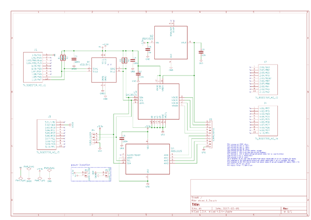
This blog documents the characteristics of the DAC/ADC BoosterPack of the electronic load that Robert Peter Oakes, jc2048 and Jan Cumps are designing.
|
Test Setup
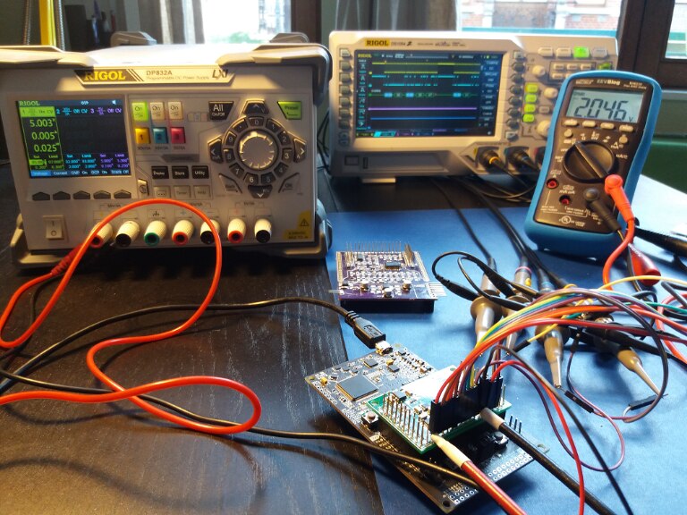
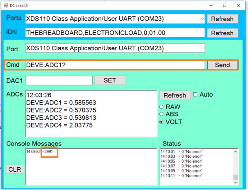
Peter has created a GUI that we can use to shoot SCPI commands. We can control the DACs and read the ADCs.
Measurements are performed with and without the power driver BoosterPack installed. We'll use 5V to power the DACs and ADCs in both situations.
 P1 and P2 on the bottom of the DAC/ADC BoosterPack have to be open. Else you'll inject 5V onto the LaunchPad 3V3 rail and you'll damage components. P1 and P2 on the bottom of the DAC/ADC BoosterPack have to be open. Else you'll inject 5V onto the LaunchPad 3V3 rail and you'll damage components. |
It's not critical if you switch on the power supply before or after you connect the LaunchPad to your computer. The circuits are isolated.
All measurements use P3.10 as GND reference and P3.1 as reference voltage.
Setup without the power driver BoosterPack:
Mount the DAC/ADC BoosterPack on the LaunchPad.
Use a +5V power supply. It should be a decent one, current is approximately 5 mA.
Connect  with DAC/ADC BoosterPack P4.2 and
  with P4.1.
Setup with the power driver BoosterPack:
Mount the DAC/ADC BoosterPack on the LaunchPad and the Power Driver BoosterPack on top of that.
On the Power Driver BoosterPack, bridge pins P2.4, P2.5 and P2.6 to tie both opamp inputs of opamp 3D to ground.
Use a +12V power supply. It should be a decent one, current is approximately 50 mA.
Connect  with Power Driver BoosterPack P1.1
  and with P1.2.
Measurements
In the table, the first column shows what we're measuring, the second column the SCPI command to execute with Peter's GUI.
The next columns are the measurements for Peter, Jon or Jan with and without the Power Driver BoosterPack.
The last column is for comments. We can indicate odds, errors, learnings.
| Jon | Peter | Jan | ||||||
| Data Point | SCPI | Without | With | Without | With | Without | With | Measurement method |
|---|---|---|---|---|---|---|---|---|
| Supply | N/A | 4.989 V | 11.88 V | DMM | ||||
| DAC/ADC V+ | N/A | 4.989 V | 5.035 V | DMM | ||||
| VREF | N/A | 2.046 V | 2.046 V | DMM | ||||
| ADC A GND | DEVE:ADC1? | 2 | SCPI output | |||||
| ADC A VREF | DEVE:ADC1? | 10918 | SCPI output | |||||
| ADC A | DEVE:ADC1? | 1138 | SCPI output | |||||
| ADC B GND | DEVE:ADC2? | 12 | SCPI output | |||||
| ADC B VREF | DEVE:ADC2? | 10920 | SCPI output | |||||
| ADC B | DEVE:ADC2? | 1 | SCPI output | |||||
| ADC C GND | DEVE:ADC3? | 2 | 2 | SCPI output | ||||
| ADC C VREF | DEVE:ADC3? | 10920 | 10919 | SCPI output | ||||
| ADC C | DEVE:ADC3? | 26868 | SCPI output | |||||
| ADC D GND | DEVE:ADC4? | 8 | 3 | SCPI output | ||||
| ADC D VREF | DEVE:ADC4? | 10919 | 10919 | SCPI output | ||||
| DAC A 0 | DEVE:DAC1 0 | 0.000 V | 0.001 V | DMM | ||||
| DAC A max | DEVE:DAC1 65535 | 2.040 V | 2.040 V | DMM | ||||
| DAC B 0 | DEVE:DAC2 0 | 0.005 V | 0.005 V | DMM | ||||
| DAC B max | DEVE:DAC2 65535 | 2.046 V | 2.046 V | DMM | ||||
| DAC C 0 | DEVE:DAC3 0 | 0.000 V | 0.000 V | DMM | ||||
| DAC C max | DEVE:DAC3 65535 | 2.039 V V | 2.039 V | DMM | ||||
| DAC D 0 | DEVE:DAC4 0 | 0.000 V | 0.000 V | DMM | ||||
| DAC D max | DEVE:DAC4 65535 | 2.039 V | 2.039 V | DMM | ||||
| To resolve |
|---|
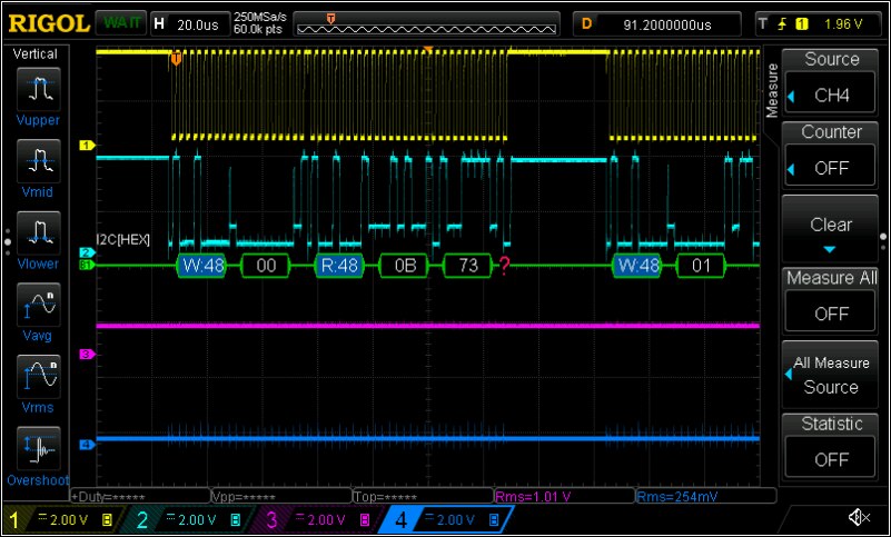
With the power driver installed, ADC C and D act strange (probably also A and B, but I didn't inject a voltage in them because they are connected to opamp pins). In particular strange for ADC D, because that one isn't routed. Strange. I will try to decrease the frequency of the sample speed and the i²c speed to see if it's related to that ...
Follow up: the cause is that OPAMP 3C injects -0.8V into ADC A. All measurements are off when that happens. As soon as I force ADC A positive (by tying it to ground or a positive voltage) all measurements are correct. |
We have a separate document to analyse the summing node at zero.


Top Comments
-

Andrew J
-
Cancel
-
Vote Up
+2
Vote Down
-
-
Sign in to reply
-
More
-
Cancel
Comment-

Andrew J
-
Cancel
-
Vote Up
+2
Vote Down
-
-
Sign in to reply
-
More
-
Cancel
Children