Six weeks ago, a package arrived on my doorstep marking the beginning of my journey into the world of supercapacitors. As a hobbyist, supercapacitors were an exotic component I had heard of, but never put into use. Thanks to element14’s “Experimenting with Supercapacitors” Design Challenge sponsored by Cornell Dubilier Electronics (CDE), I have been on a mission to understand all that I can about supercapacitors, how they work, how they behave, how to design with them and gain practical experience in integrating them into various applications.
This final blog marks the end of my journey, collating all the learnings I have made throughout (as required by the new-format “experimenting with” challenges). While I have made comprehensive weekly blogs, this blog will try to bring all the learnings together in a “question and answer” format. As a result, this blog is slightly less detailed (to avoid being even longer and running into limitations on embedded content) and readers should refer to the detailed weekly “extra credit” blogs for more detail (including code listings or downloadable files). Readers who have followed on with my weekly blogs will note some minor corrections which are made within this blog.
So, what’s super about supercapacitors? Quite a lot, actually …
Table of Contents
- Q1: What’s a Supercapacitor?
- Q2: Who makes Supercapacitors?
- Q3: What’s in the Kit?
- Q4: Supercapacitor Weight and Charge on Arrival
- Q5: Lithium-Ion Capacitor (LIC) Hybrid Supercapacitor Safety
- Q6: Can you Measure Supercapacitors with LCR Meters or DMMs?
- Q7: How to Measure Capacitance?
- Q8: How to Make ESR Measurements?
- Q9: How to Perform (and Performing) Leakage Current Measurements?
- Q10: How to Keep Charged Supercapacitors Apart?
- Q11: How to Design a Supercapacitor Solution?
- Q12: Supercapacitor Lifetime vs. Voltage and Temperature?
- Q13: How Much Power Can You Get from the Provided Solar Panel?
- Q14: What are the Chemicals Inside a Supercapacitor?
- Q15: What Happens Under Reverse Polarity?
- Q16: What Happens Under Overvoltage?
- Q17: What’s Inside a 5.5V Supercapacitor?
- Q18: Can it be Used to Replace Coin Cells for Power Backup?
- Q19: What Happens Under Cyclic Charge/Discharge?
- Q20: What Happens Under Repeated Short-Circuit?
- Q21: Building a Solar-Powered LoRaWAN Particulate Monitor Sensor
- Q22: Series-Connected Supercapacitor Imbalance in Practice?
- Q23: How do Supercapacitors Perform in Low Temperatures?
- Q24: Practical Use of LIC Supercapacitors in a LED Blinker
- Conclusion
- Appendix: Acknowledgements
Q1: What’s a Supercapacitor?
Supercapacitors, sometimes also known as an ultracapacitor, are capacitors with much higher capacitance than ordinary capacitors but with a lower voltage capability. They are more energy dense than ordinary capacitors (by around 1,000x to 100,000x), but much less so than batteries, occupying a space in-between when it comes to energy and power density. They have a much higher cycle life than batteries, although their operational lifetime and temperature capabilities mostly fall behind that of ordinary capacitors.
Such components see applications in memory back-up, power-loss protection in computing, short-term ride-through for UPSes, burst-power requirements for car audio, medical devices, electric vehicles and even wind-turbines and kinetic energy recovery systems. Their use is primarily based on the need for rapid charge/discharge and frequent cycling, whilst maintaining adequate energy density (both in terms of weight and volume) and cost.
There are a number of types of supercapacitor, the most traditional being the Electric Double-Layer Capacitor (EDLC). These use activated carbon electrodes with electrostatic storage of charge in a double-layer between the electrode and electrolyte. Such an arrangement improves energy density above that of ordinary capacitors mainly due to the reduced charge separation distance and increased surface area of the activated carbon. A key downside of this, however, is that the structure of the capacitor acts like an array of parallel connected capacitors with different series resistances – to fully charge (soak) the capacitor takes a long time.
The next most common type, and a more recent development, is the Lithium-Ion Capacitor (LIC) which is a type of hybrid capacitor. It draws upon the structure of the EDLC, but replaces the anode with that found in a lithium-ion battery. As a result, it takes some of the characteristics of a lithium-ion battery (e.g. higher voltage, lower self discharge, higher energy density) and combines them with the characteristics of EDLCs (e.g. high cycle life, lower ESR than batteries, improved safety).

For a more comprehensive review on the technology, I’d highly recommend Karimi et.al. (2022) A Comprehensive Review of Lithium-Ion Capacitor Technology: Theory, Development, Modeling, Thermal Management Systems, and Applications, MDPI Molecules (open-access).
Perusing the various electronic component distributor sites including element14 and Newark, it is possible to find supercapacitors ranging from 10mF to 6000F with products being single components for integration into mainstream or portable electronics through to large modules intended for industrial and transportation use. Voltage ratings ranged from 1.4V to 850V where the higher voltages are formed by modules with balanced series-connection of multiple supercapacitors. Typically EDLC have 2.7V or 3.0V nominal voltages and LIC have 3.8V nominal. Lifetimes range from as low as 500h or 1000h at 50°C up to a high of about 6000h at 85°C which is still less than some of the best wet electrolytic capacitors of today, possibly due to issues with “wetting” and “leakage” of internal electrolytes which seem particularly aggressive and are an industry-wide issue according to VINATech. The ESR ratings range from 200µΩ up to 300Ω depending on the product.
Q2: Who makes Supercapacitors?
After spending some time scouring electronics distributors, I found the following companies to make or have supercapacitor components in their catalogue:
- EDLC
- Abracon
- CDA (Zhifengwei Technology)
- Cornell Dubilier (CDE)
- Eaton
- Kemet
- Kyocera AVX
- Lelon Electronics
- LICAP Technologies
- Maxwell Technologies
- NIC Components
- Nichicon
- Nippon Chemi-Con
- Ohmite
- Rubycon
- Samxon
- Skeleton Technologies
- Taiyo Yuden
- Tecate Group
- VINATech
- Vishay
- Würth Elektronik
- Yongmin Electronic (Ymin)
- LIC
- CDA (Zhifengwei Technology)
- Cornell Dubilier (CDE)
- Eaton
- LICAP Technologies
- Taiyo Yuden
- Tecate Group
- VINATech
Notably, I have omitted ELNA, Panasonic and TDK/EPCOS from the list as all seem to be discontinuing their lines of EDLC. Panasonic EOL’d all their lines on 1st October 2020, while ELNA has issued NRND notices 1st July 2023 for their EDLC products with no alternatives. A banner also indicates NRND status for all EDLC in TDK’s portfolio. I’m not sure if Rubycon is continuing with their series – even though inventory is available, the DMB series does not appear on their English website. Some other companies specialise in supercapacitor modules comprising multiple cells and were not included in this list.
During this deep dive, I also discovered the reason behind the “IC” branding on the capacitors from Cornell Dubilier – they are actually Illinois Capacitor products but since Cornell Dubilier Marketing had acquired Illinois Capacitor in 2015, they now fall under the CDE banding.
Q3: What’s in the Kit?
The kit includes a mix of radial lead EDLC supercapacitors from the DGH and DGS series, and LIC supercapacitors from the VMF and VPF series …
… and coin-cell modules from the EDC and EDS series.
I’ve extracted all of the key parameters from the datasheet (where given) and tabulated it with colour-coding and some calculated values of my own.
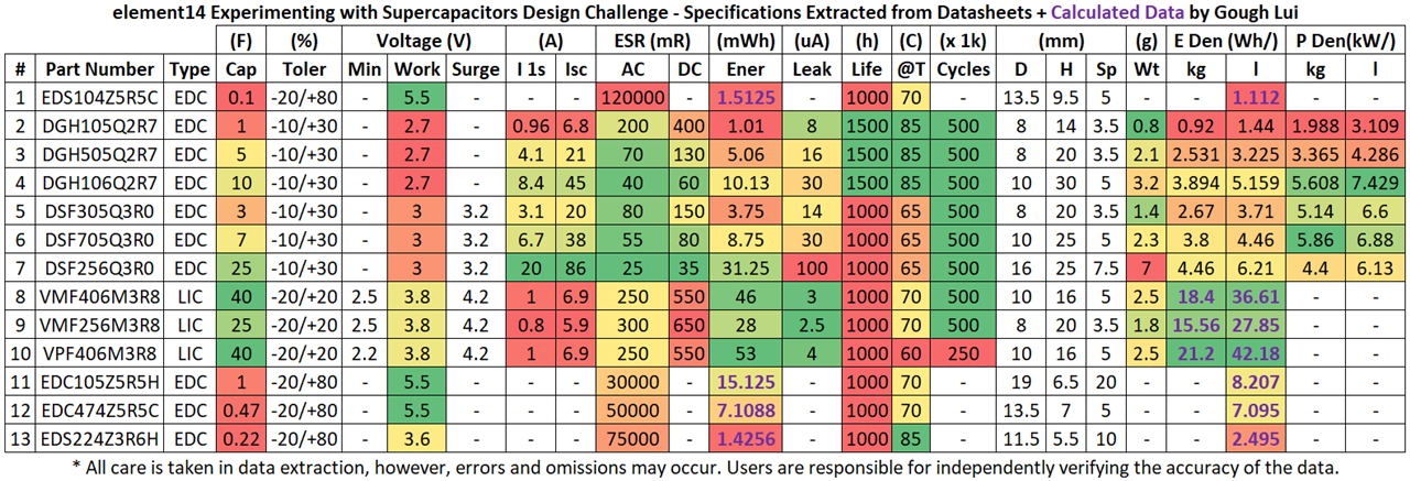
The range of capacitances is quite large with some overlap between EDLC and LIC products. The EDC stacked cells have a voltage rating of 5.5V, while most of the ordinary EDLCs have a 2.7V/3V rating with LICs having a 3.8V rating. The exception is the EDS224Z3R6H which has a 3.6V rating instead. Current delivery and internal resistance figures generally get better with increasing capacity which also correlates with the size of capacitor. The radial lead capacitors in the set range from 8 to 16mm diameter and 16 to 30mm height, while the coin-cell type ranges from 11.5 to 19mm diameter and 5.5 to 9.5mm height. Rather unsurprisingly, if looking at the energy in mWh, the capacitors have a very small amount of energy even compared to a true-wireless stereo earbud battery (3.7V/40mAh = 148mWh).
Nevertheless, the advantages of LICs in terms of energy density are clear as they are almost an order of magnitude better. A more limited voltage window, cycle life limitations with more limited temperature window and internal resistances are, however, the price that is paid for this.
Note: earlier versions of this table incorrectly specified the AC ESR values for EDC/EDS series products. Thanks to misaz for pointing this out.
Q4: Supercapacitor Weight and Charge on Arrival
Checking the supercapacitors, I decided to use my rather accurate Muticomp Pro BAL1 scales to measure the weight to the milligram to see how consistent the product is …
… and my Fluke 279 FC True RMS Thermal Multimeter to measure the charge on the capacitor (if any).
The results are as follows:

The weights in bold differ significantly from the datasheet. The DSF705Q3R0 is stated as weighing 2.3g while the DSF256Q3R0 is stated as weighing 7.0g which suggests that the energy density figures for these products may be a little optimistic as the measured weights were 0.3-0.5g higher. On the whole, most weights were close to the datasheet value and the pairs of weights were reasonably close together. Voltage-wise, most capacitors were very close to zero – mostly below 100mV with some minor negative readings as well. However, the voltages for the LICs were all over the place – some had charge, others didn’t.
Q5: Lithium-Ion Capacitor (LIC) Hybrid Supercapacitor Safety
Due to the similarities between lithium-ion batteries and LICs, there may be some hesitation about the safety of such products. However, it seems that the replacement of the anode of an EDLC with that from a lithium-ion battery results in a structure that is immune to thermal runaway even with a dead short-circuit via a nail puncture test even when the cell reaches above 100°C.

From Taiyo Yuden’s Whitepaper - TAIYO YUDEN Lithium Ion Capacitors: An Effective EDLC Replacement
In fact, it seems that supercapacitors with less than 0.3Wh are not regulated and are exempt from dangerous goods or HAZMAT shipping regulations which was interesting to know
Unfortunately, there is one safety aspect which seems to have already been violated – namely that some of the lithium-ion supercapacitors have a voltage below the minimum voltage. After digging through documentation, I have come to the consensus that this is not good for the capacitor and may even result in failure or be dangerous.
According to CDE, the LIC supercapacitors are “charged with voltage between 3.6V - 3.8V from the time of shipment and should be used within the working voltage range of 2.2V - 3.8V. Exceeding this may cause leakage or explosion. If discharging lower than 2.2V, it will cause capacitance reduction and ESR increase reducing the life of the product.” With thanks to scottiebabe for digging this one up, when I was relying on sources from other manufacturers.
I suspect the packaging of capacitors such that the legs could touch in shipment was probably the cause of the capacitors being over-discharged causing permanent damage, but perhaps still partially recoverable.
Q6: Can you Measure Supercapacitors with LCR Meters or DMMs?
When it comes to measuring capacitors, one of the first items you might be thinking of using is an LCR meter or a digital multimeter.
But in reality, such meters are often not a good choice for measuring supercapacitors. This is because most of these meters top out at 10mF or even less. This is not enough for supercapacitors – the smallest in our kit is 100mF and the largest is 40000mF to put it into perspective.
The second reason is that many of these meters cannot handle charged capacitors. Lithium-ion (LIC) hybrid supercapacitors will be charged at all times in normal operation and thus cannot be measured on such meters without potentially causing damage. Even with ordinary electric double-layer (EDLC) supercapacitors may hold sufficient residual charge even at low voltages that they could stress the meter.
But all is not lost … there are other ways of measuring capacitance and the LCR meter may not be entirely worthless.
Q7: How to Measure Capacitance?
As supercapacitors are so big, the measurement techniques used share more similarity with batteries. Ideally, the use of a source measurement unit (SMU) is required for accurate measurements.
Cornell Dubilier’s Technical Guide gives a few methods, with a number of different charge/discharge rates. Not satisfied with this, also I consulted the AVX datasheets which had clearer guidance.
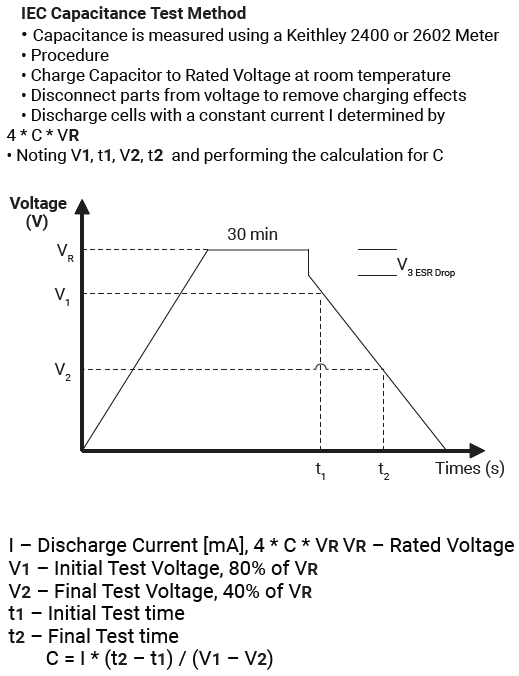
The IEC method for measuring capacitance uses 4*C*Vr as the current in mA (i.e. 10.8mA/F to 22mA/F depending on voltage). The capacitor is charged to rated voltage and disconnected. Then after 30 mins, it is discharged at constant current with 80% and 40% voltage points used for computing capacitance. That being said, this was not the method I employed as there was another method which seemed more convenient.
Q8: How to Make ESR Measurements?
Another key parameter for capacitors is their equivalent series resistance (ESR) or internal resistance (IR). This can be imagined as a “restriction” that leads to energy dissipation as heat which can shorten the life of the capacitor and restricts the current capability. There are two common methods – AC ESR and DC ESR which are not interchangeable. Usually the DC ESR is greater and represents the voltage drop you would experience under load, while the AC ESR tells us a bit about the internal electrochemical status of the capacitor without causing any net charging or discharging.
AC ESR
The AC ESR is ordinarily performed by injecting a small symmetrical 1kHz AC signal into the capacitor and measuring the current and voltage magnitude to determine the resistance. In this case, it actually can be acceptable to use an LCR meter on discharged EDLC capacitors for this purpose as the ESR value is usually within the range of the meter even if the capacitance is not.
Ideally you should use an LCR meter that can handle voltage across its inputs. Thankfully, I have one in the form of the B&K Precision BA6010 Battery Analyser – it’s basically an isolated 1kHz AC LCR meter that can handle a voltage up to 60V across its input making it acceptable for measuring even charged LICs.
You might be surprised to see the capacitance is not measuring “correctly”. This is actually proper behaviour – because the capacitor doesn’t have anywhere near as much effective capacitance at 1kHz. In essence, supercapacitors are too “slow” to react at such high frequencies – in fact, it’s been stated in several datasheets that they’re not even meant to be used for smoothing out ripple as that can shorten their life expectancies dramatically.
DC ESR
The DC ESR can be determined through charge and discharge tests similar to the test for capacitance, although the rate and timings can be different depending on which procedure is used.
Cornell Dubilier’s Technical Guide recommends a rate of 1mA/F with holding the voltage for 1 minute. The values for V1 and V2 are not given.
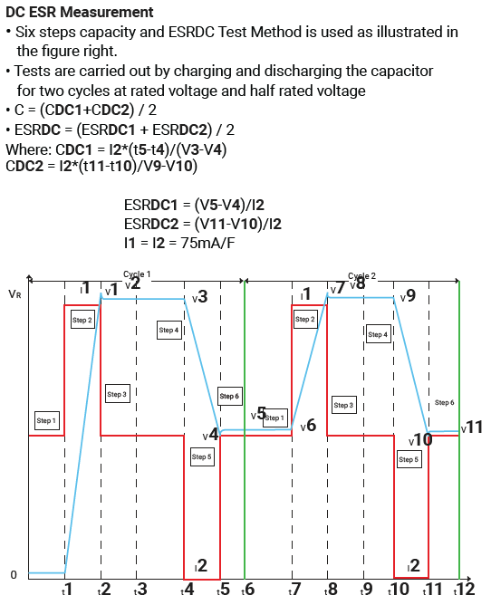
Consulting the AVX datasheets again, they propose a six-step DC ESR and capacity measurement methodology. This takes a two-cycle approach with a rate of 75mA/F instead. However, the short dwell time may mean that some supercapacitors may not have the time to charge fully.
Measured Characteristics
For this experiment, I used the Keithley 2450 SourceMeter as my measurement instrument along with two scripts I have developed that implement a “fast” method based on the AVX datasheet and a “slow” method which is based on the IEC/CDE recommendations.
In the case of EDLC, the script first discharges the capacitor to zero (prior to logging), charges the capacitor from zero, dwells for 60s, discharges to V/2, rests for 60s, charges to V, dwells for 60s, then discharges to 0.1V. Capacitance values are calculated based on the V to V/2 time.

In the case of LIC, the script instead will discharge the capacitor to 2.5V (prior to logging). The other steps are similar but instead of V/2, a lower limit of 2.5V is used. Post-test, instead of discharging, the capacitor is recharged to 3.6V for storage. Capacitance values are calculated based on V to 2.5V time.

Using the same data, the DC ESR was determined from the samples around the load-step. This is repeated for both down-slopes so each “fast” run resulted in two values for capacitance and DC ESR.

The slow method was implemented with a discharge to 0V prior to commencement, a 30-minute dwell time while remaining connected to voltage (to more thoroughly charge the supercapacitor) and discharge to 0.1V. Capacitance is calculated between 0.8*V and 0.4*V. As a result, this is not strictly adherent to IEC methodology but is more convenient.

A similar change was made for LICs in the slow method, a discharge to 2.5V prior to commencement, discharge limited to 2.5V (as the end-point) and recharge to 3.6V for stage post-test.

Connections were initially done as two-wire with clips, with null compensation for lead resistance.
Later tests were performed in four-wire mode to remove lead resistance effects. Polarity was doubly-verified prior to each test to ensure no damage to the supercapacitors.
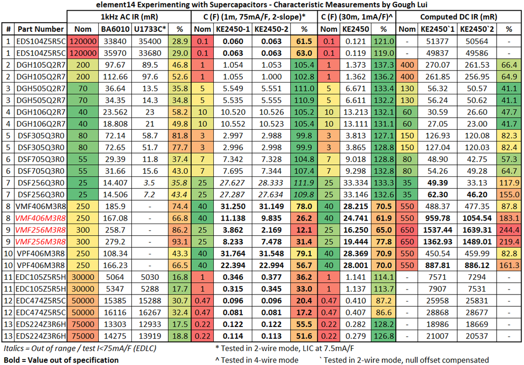
The capacitor part numbers in red are the units that were over-discharged. Tests done with a * indicate two-wire mode was used, with ` indicating that the null resistance compensation was performed to take away lead resistance. Tests indicated with ^ are done in four-wire mode.
All supercapacitors were within range for AC ESR, however, DC ESR showed some marginal readings for DSF256Q3R0. Interestingly, the over-discharged LICs all showed significantly elevated ESRs (VMF406M3R8, VMF256M3R8) which appear inversely-correlated to the state-of-charge as received (i.e. deeper discharge = higher ESR). One of the not-overly-discharged LICs (VPF406M3R8) also seems to have a consistently higher DC ESR than datasheet which was slightly surprising, but not as significant as the over-discharged units.
Capacitance values as measured using the “fast” method shows all EDC/EDS coin-cells and LICs as having less capacitance than rated. I suppose this is because there is insufficient time for the supercapacitors to “soak” a full charge, especially for the coin-cell type.
Repeating the test with the “slow” method finds all EDC/EDS coin-cells to now comply, while the radial-type DGH/DSF series are all “over-performing”. Unfortunately, all LICs (VMF/VPF series) are under-performing even with the 30-minute dwell time and I am unsure as to the cause. In some cases, the results of this slower test were even worse than the fast mode – suggesting something may have happened to the capacitor in test.

Looking closely, it is clear that all supercapacitor charging, even EDLC, are not entirely linear, so the choice of start- and end-points can have an influence in the computed capacitance figures.

Recovery of the over-discharged LIC actually results in a very non-linear voltage curve under constant-current charging. This suggests to me some sort of electrochemical process may be happening. The performance is inconsistent.

However, on subsequent charges, it seems to behave more normally, suggesting the “recovery” charge is permanent in reverting the state of the capacitor, but this may not recover the full performance especially if the over-discharge is repeated.
Q9: How to Perform (and Performing) Leakage Current Measurements?
The leakage current of a supercapacitor is the current it draws when it is fully charged. This is usually a good indicator about the state of the internals of any capacitor and is of vital importance especially in energy harvesting applications where the leakage represents a parasitic load that is “wasting” away energy. We can expect the leakage current to be in the one to several-hundred µA region.
One way to measure this would be to use a Source Measurement Unit (SMU) to supply the fixed rated voltage to the supercapacitor for a 72-hour period (to ensure it is fully charged) and measure precisely the small amount of current still flowing into the unit. The use of an SMU is recommended due to the small currents involved, requiring a rather precise measurement capability that is lacking in most power supply units (PSUs) and avoiding any issues with burden resistances.
However, such an approach is expensive as SMUs are not cheap – I only have one and if each capacitor took 72 hours to test, I’d need 78 days to test the whole lot. I don’t have 78 days …
Thankfully, I came across this simple “compromise” arrangement in an AVX datasheet:

Put simply, you can use a DC power supply and a sense resistor (1kΩ) that is shorted over for the first 72 hours. Once the time has elapsed, you remove the short so that the capacitor is powered through the sense resistor and you measure the voltage across the resistor after a ten-minute stabilisation period to know the current. This method is not 100% accurate as there is a tiny burden voltage caused by the sense resistor that may mean that the leakage measured is a slight underestimate, hence the ten-minute stabilisation period to let everything equilibrate. The major advantage of this method is that it is simple, inexpensive, easily parallelisable and doesn’t require any high-end equipment.
For the AVX method using a power supply, I opted to call upon my Rohde & Schwarz HMP4040 four-channel power supply (that they generously restored the 4th channel for me last year). Supercapacitors were connected onto breadboards and bussed together for charging.
The first breadboard had all the radial EDLCs.
The second breadboard had all the LICs and coin-cell EDLCs excepting the 3.6V rated ones.
The power supply was turned on and the capacitors were left to charge for the 72-hour period. A decrease in current is noted on the display.
Towards the end of the period, 1kΩ 1% tolerance sensing resistors were installed.
Reaching the end of the period, the jumpers were removed.
Following a 10-minute stabilisation period, the voltage across the resistor was measured with a Keithley 2110 5.5-digit Digital Multimeter set to 10PLC and 16 averaging.
For the SMU method, a two-wire connection is used through alligator clips, similar to that illustrated in previous blogs.

The results of the tests were surprisingly good, with almost all capacitors reading below 15% of the rated leakage current (where a rating is available). Overall, leakage currents ranged between 0.8µA to 4.4µA at beginning of life. I do expect leakage currents to increase as capacitors age. There was one key outlier – a damaged VMF406M3R8 which measured higher than the other LICs, but not high enough to fail. However, other damaged LICs didn’t show such a marked increase in leakage current. This may indicate that overdischarged LICs may be damaged inconsistently by the overdischarge event.
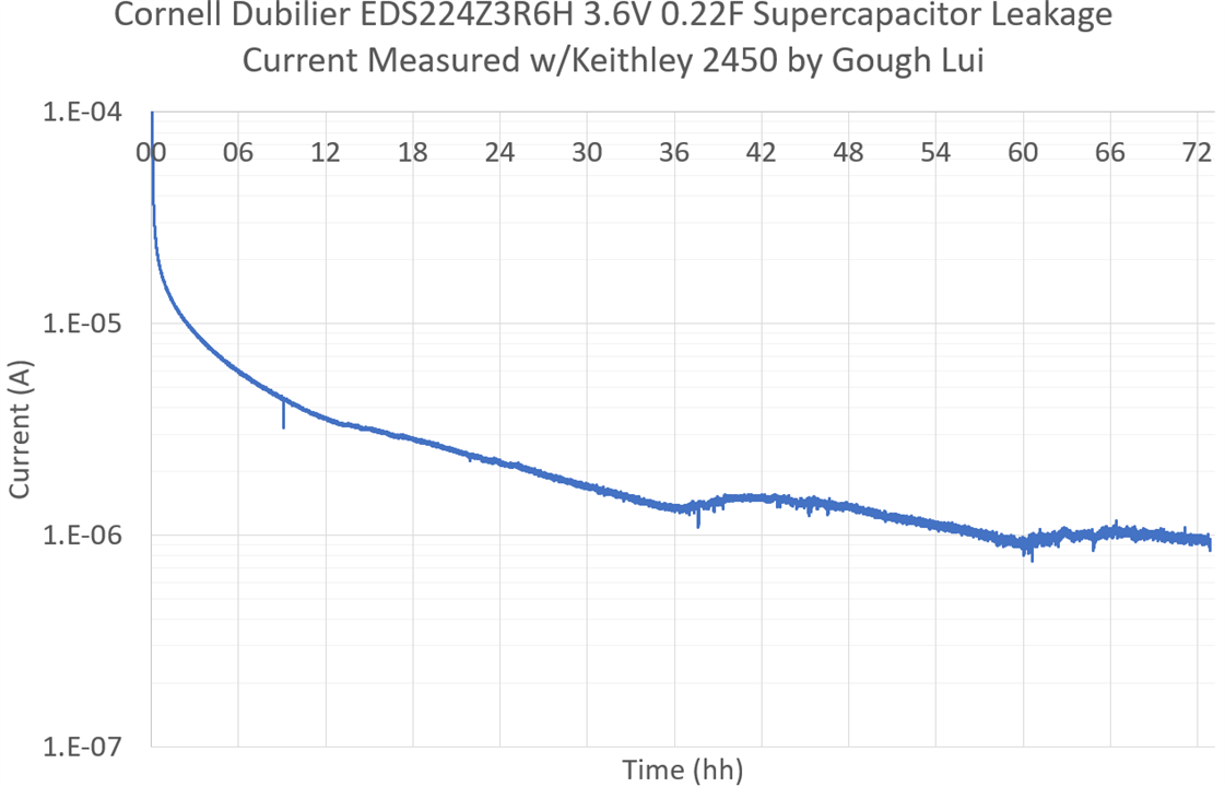
The current consumed by an EDS224Z3R6H as recorded by the SMU shows the reducing current as the capacitor charges over the 72-hour period. Some perturbation in the trend is seen due to uncontrolled room temperature variations. While the majority of the supercapacitor charges relatively quickly, the “long-tail” is visible.
Note – I did not plot the result of the first SMU measurement as it had very unusual spikes towards the end of the test. The cause of these spikes were determined to be the auto-ranging behaviour of the KE2450 – when it decides to change range, it stops sourcing for a short period as the range is changed. Because of this discontinuity in voltage/current, the capacitor doesn’t resume charging at the same current and given enough time, the capacitor can cause the SMU to enter a nearly-continuous auto-ranging loop. Once I noticed this, I decided to manual-range the SMU at appropriate times and the problem (mostly) went away. This is one downside of SMUs where the sensing and sourcing are intimately linked.
Q10: How to Keep Charged Supercapacitors Apart?
Unfortunately the sorter case we were provided doesn’t have enough slots for each capacitor to sit in its own slot, so I decided to fix this by dividing each box into two.
To do this, I designed a simple piece of flat plastic that would be inserted diagonally into each compartment. Going diagonal has the benefit that such an insert is self-supporting, won’t fall over and needs less material than a fully supported T-shape.
Thus, the solution is born and supercapacitors should short out no more … unless their legs are forcibly bent towards one another. Better than nothing, especially since I don’t have any styrofoam on hand.
Q11: How to Design a Supercapacitor Solution?
A simple way to design a supercapacitor solution would be to go through the following aspects:
Load Profile
Generally speaking, supercapacitors are best suited for demands which are no shorter than 1-10s for pulse/peak-power applications depending on the type of supercapacitor. At the short end of the scale, the ESR limits peak currents achievable which can result in heating and limitations in lifetime. It would seem that radial types, larger cells and even multi-cell modules are much more suited to these types of applications. Shorter time-scales are better served by ordinary capacitors – e.g. filtering out mains ripple. Meanwhile, relatively low-current (mA) memory back-up applications can be serviced by coin-cell style EDLC supercapacitors which can be “trickled” in standby waiting for a power interruption.
Tolerable Voltage Window
Understanding the tolerable voltage window for your system is important to maximise the capacity use of the supercapacitor. The issue is that the system that is connected likely cannot operate throughout the whole voltage window of the supercapacitor. For example, an ESP32 may operate between 3.0V (internal flash type) to 3.6V only. Using a linear regulator could extend the upper voltage range at the cost of quiescent current and power loss when the voltage is above the required voltage, while a switching converter may improve the tolerable voltage range by buck-boosting the supply at the cost of complexity and quiescent consumption. Simple implementations of supercapacitors may result in inefficient use of the available capacity owing to a limited window of voltage being useful.
Number in Series
Depending on the supercapacitor type in use, you’re likely going to need more than one in-series to get the necessary voltage for your load. In the case of an ESP32 that can operate at 3.6V, this would mean having two EDLCs in series, although a single LIC would do just fine as well.
While series capacitors add voltage ratings, the capacitance instead follows a 1/(1/C1+1/C2+…+1/Cn) relationship. Because of this, it may be necessary to have multiple series strings in parallel to meet the required capacity.
But having more than one supercapacitor introduces a complication – no two components are identical. Because of differences in capacity, ESR and leakage rates, charging the series-connected capacitors with the same current will result in them being at slightly different voltages. If you had two 2.7V EDLC supercapacitors in series, it would be very unwise to try charging it to 5.4V as one could be at 2.9V and the other could be at 2.5V especially at end-of-life when characteristics may diverge. As a result, some balancing may be required.
Two classes of balancing circuit exist – passive balancing often just relies on having resistors which “waste” current in such a way that the unit with higher voltage suffers a greater draw that pulls down its voltage compared to the unit with lower voltage. Such a system, while simple, is often inefficient and only suitable where the current loss is acceptable. Active balancing relies on a circuit that uses the voltage to drive a transistor to shunt current around a supercapacitor that has reached its maximum voltage.
A simple way around the whole balancing scenario is simply having enough headroom to accommodate the worst-case scenario. For example, with two 2.7V EDLC supercapacitors in series, if they were only charged to 3.6V total, this puts just 1.8V on each in the balanced state leaving a massive 0.9V of headroom. Depending on which source you read, 0.2V to 0.3V headroom may be sufficient to avoid the need to balance with well-made supercapacitors.
Load Current and Voltage Drop by ESR
In order to understand the capacity required and just how long you might get out of a given supercapacitor, it is necessary to understand the load current. For the ESP32 example, let’s imagine the unit is transmitting Wi-Fi in its slowest mode, consuming 240mA according to its datasheet.
We know based on I=C*dV/dt that dt =C*dV/I. Assuming a capacitance of 1F, going from 3.6V down to 3.0V, dV = 0.6V and I = 0.24A. Therefore, the expected hold-up time is 2.5 seconds for a 1F capacitor. This may not sound like much, but it’s a lot more than what you’d get out of a capacitor.
There is a wrinkle though … that is the theoretical ideal hold-up time. In reality, you get a sudden voltage droop as the load is placed on the supercapacitor due to its ESR. Assuming an ESR of 100mΩ, this droop will be 0.024V, reducing dV to 0.576V and the hold-up time to 2.4 seconds. The ESR will be entirely dependent on the model of supercapacitor used and is usually worse at end-of-life, so it may make sense to use 200% of the initial ESR rating for this calculation.
If you need more time, add more capacitance. But perhaps your system is lazy and operates at 3.3V and you have no convenient source of 3.6V to use. In that case, your dV is down to 0.3V in the ideal case and your hold-up time is just 1.25s in the ideal case. If you have an (ideal) lossless linear regulator and your supply is 5V, then you have expanded your dV to 2V and the same capacitance will give you a hold-up time of 8.3 seconds. Of course, these figures are made based on the pessimistic transmit-burst power – actual running current for the ESP32 on average is about half of this. This is why being able to fully utilise the voltage span of the supercapacitor is important to maximise its usable capacity.
The choice of capacitor will also need to consider factors such as size, weight, cost and lifetime.
Q12: Supercapacitor Lifetime vs. Voltage and Temperature?
Having replaced many electrolytic capacitors in my time due to the capacitor plague, when I saw lifetimes stated of 1000h or 1500h at relatively low temperatures of 60°C to 85°C, this made me somewhat nervous about using supercapacitors. There are 8760 hours in a year after all. Furthermore, I knew from experience that any electrolytic capacitor worth its weight has a rating of 105°C and a load lifetime of usually 8000h+ for a quality unit. Nichicon ULDs now claim 10-20k hours at 105°C which is more than plenty!
Are the relatively low stated lifetimes and temperature ratings a problem in practice? I decided to approach this problem using the equation given by Cornell Dubilier’s documentation. Using this, I was able to calculate the lifetime for the CDE supercapacitor series in this Design Challenge under various temperature and voltages. Cells shaded in dark grey are outside the operating window for that supercapacitor type, while cells shaded in light grey are acceptable but are extended above the test conditions or are surge-rated.

I truncated all results over one-million hours as that’s over 100 years and failure due to other causes is very likely. For the DGH series, there is a slight wrinkle – the nominal voltages at the test temperature are below the commonly stated 2.7V/5.5V values. It seems that if it is used under room temperature conditions, use at the nominal rated voltage shouldn’t be an issue – the 5.5V part would last in excess of four years while the 2.7V part would last in excess of 37 years. However, if operation occurs inside a case, a computer case is commonly stated as 50°C, in which case a slight voltage derating would be recommended. The DSF series shows a similar result.
The EDC series are higher-temperature units that claim long lifetimes and this is borne out in the modelling. The EDS series are even higher-temperature long-lifetime units but with different voltage ranges. In this case, the modelling suggests these will operate well across higher temperatures at their rated voltage.

Comparatively, the LIC-based VMF and VPF series are more delicate due to the low temperature ratings. At room temperature, stepping back on voltage would ensure a longer lifetime. In an enclosed condition with elevated temperatures, the voltage may have to be stepped back further to 3.3-3.6V. Perhaps this is one of the downsides of LICs.
While ambient temperature and voltages can easily be controlled, the capacitor temperature will increase during ordinary usage due to internal dissipation self-heating which should also be taken into account, which could increase temperatures by up to 20°C (depending on current).
Q13: How Much Power Can You Get from the Provided Solar Panel?
The included panel claims to be a 5V 100mA panel, but lacks key specifications ordinarily found on most solar panels.
There is a box on the back of the panel – I opened it up to find there was no circuitry at all. This is just where the wires connect to the PCB module.
In order to ascertain how much power is truly available under ordinary sunny conditions from the “5V 100mA” panel, I had to run some I-V curves. In order to do this, I dug through my junk box for a 2.1mm x 5.5mm panel mount socket to use for connectivity.
I took the Rohde & Schwarz NGM202 power supply outside and sat it in the backyard on a chair with the panel propped up on a medicine box. Hooking it into power was all that was absolutely necessary, as the NGM202 has on-board 2.4GHz Wi-Fi for network-connected SCPI commanding. The sun shining on the instrument was also not a good idea. Nevertheless, I swept the panel continuously for two hours either side of noon.

The returned data was noisy – this is not unexpected as birds, clouds, the motion of the sun and other obstructions cause the light received by the panel to be inconsistent. Interestingly, a lensing effect can occur with clouds where solar intensity dips but also rises under certain circumstances. Taking the average was not sufficient (in red), but the eyes can make out what the trend is and ultimately, it seems the panel does meet the specifications assuming it is Voc and Isc. Estimated actual maximum power is around 432mW at 4.55V/95mA with a fill factor of just 70%, so expecting to run a 5V device off this alone, reliably, is not likely unless you can stay below 70mA.
Q14: What are the Chemicals Inside a Supercapacitor?
As supercapacitors are finished components intended for integration into other products with no safety issues under normal handling and they’re usually not likely to be ingested, finding out what is inside a supercapacitor with regards to its chemical composition can be difficult.
After some research, I was able to identify the following Material Safety DataSheets (MSDS) from other manufacturers with differing formulations:
I did not find any for CDE’s products or hybrid LICs in particular, but I have little reason to believe they would be substantially different.
Key ingredients aggregated across all MSDSes include:
- Activated Carbon (15-35%)
- Carbon Black (0-12%)
- Paper/Cellulose (2-12%)
- Aluminium (25-50%)
- Propylene Carbonate
- Tetraethylammonium tetrafluoroborate (5-35%)*
- Acetonitrile (5-40%)*
- Proprietary Cyano-substituted Hydrocarbon*
- Proprietary Hydrocarbon Substituted Nitrogen*
Items marked with * are potentially of concern, with exposure limits and are known to be toxic, cause irritation or are flammable. The first italics entry appears to be related to the plastic casing used in Cooper Bussman’s PM-series supercapacitors. The latter two in italics seem to be uncommon and are proprietary to the Ioxus MSDS. The remainder appears to be consistent across datasheets.
Some further research on acetonitrile suggests that it is mildly toxic due to being metabolised into hydrogen cyanide after a delay of up to 12 hours but poisoning is rare with an LD50 oral of 2460mg/kg. Because of the proportion in the supercapacitors and the size of the capacitor, this is not a major concern. Tetraethylammonium tetrafluoroborate is a little more mysterious, however, as it is both listed as an irritant and causing acute toxicity, but data on exposure limits appears to be lacking.
As a result, it’s probably not a good idea to breathe in any fumes generated or touch any liquids that may come out of supercapacitors … although that’s probably common-sense anyhow.
Q15: What Happens Under Reverse Polarity?
Supercapacitors, being polarised components, should always be used in line with their indicated polarity. That being said, during my early research, I discovered that the structure of an ELDC is symmetrical which theoretically would mean that reverse polarity would not damage the EDLC. I also discovered that LICs were asymmetrical with their configuration and seemed unlikely to tolerate reverse polarity. Seeing we already had some over-discharged LICs, I wondered how they would fail.
To test this, I used the slow 1mA/F capacitor testing script in the previous part with my Keithley 2450 SourceMeter to measure the capacitance, but in reverse for three cycles, then forward-biased for three cycles. I also measured the AC ESR using the B&K Precision BA6010 to ascertain if there were major differences. I did this for a 2.7V EDLC, 3V EDLC and 3.8V LIC.
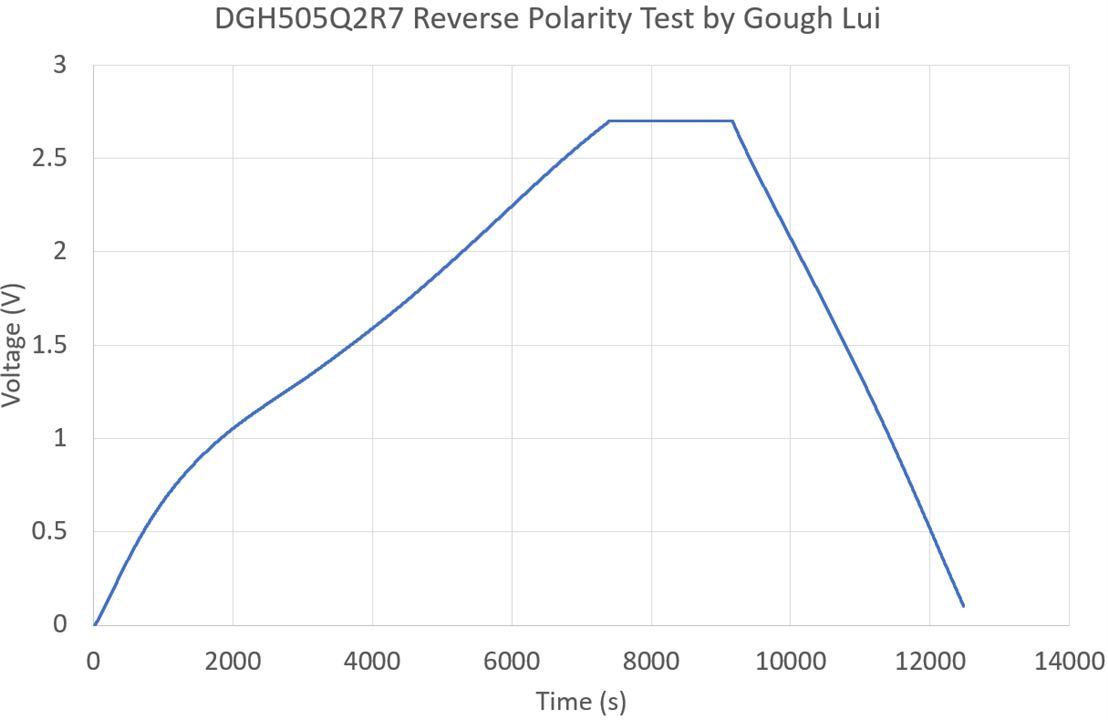
Rather unsurprisingly, the information about the EDLCs seems to be true – a slight non-linearity is seen at the low voltages, but the charging and discharging was successful with the 2.7V EDLC (DGH505Q2R7).
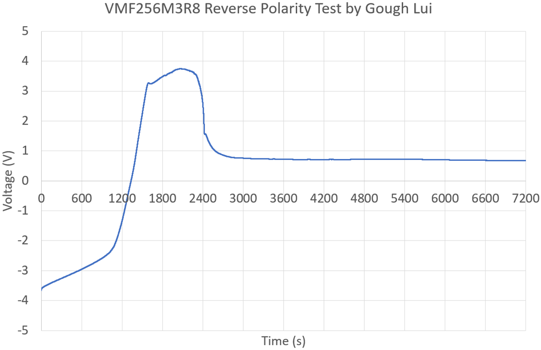
The LIC (VMF256M3R8) tested did not survive the reverse-polarity treatment. In fact, the script could not be aborted while saving the data, so a second LIC had to be sacrificed in this test. Of note is that both were over-discharged and recovered prior to the test, so they may not be representative of stress-free LICs. Nevertheless, the discharge from charged state is relatively linear until hitting about 2.4V when it rapidly accelerated to a new slope. This slope extended until about 3.2V in reverse when some breakdown might have occurred, flattening the curve and turning it around after some time to a soft-shorted condition.
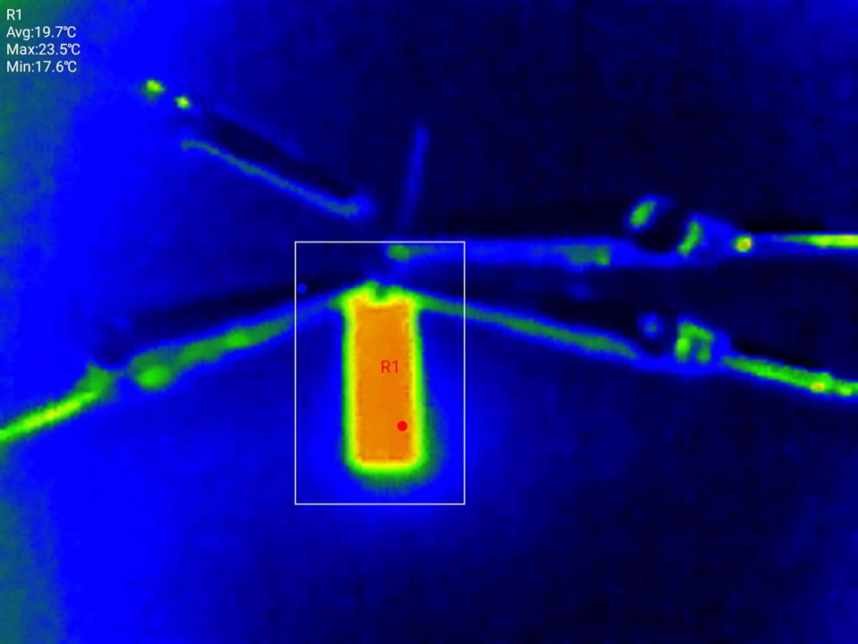
The capacitor was only seen to warm-up ever so slightly compared to background temperature throughout this process, never reaching any dangerous temperature.

Applying forward current did not recover the capacitor’s function, even after an hour, resulting in a capacitor that was soft-shorted in both directions. Of note is that under such conditions, the capacitor showed no external signs of distress as power dissipation was quite limited. Under high-current conditions, this may not be the case.

Looking at the measured capacitance, it seems that the EDLC parts survived practically unscathed in terms of capacitance. The AC ESR figures seems to have gone either way by a small amount – in no way are the parts unserviceable although their long-term safety could still be under question. The LICs both soft-shorted internally and were no longer capacitors after the first reverse-polarity excursion. The AC ESR figures both showed increases – one approximately doubling which would usually indicate end-of-life, but are otherwise inconclusive.

Referring to Taiyo Yuden’s whitepaper, it seems that the over-discharge and reverse polarity likely caused the voltage on the anode to increase beyond its tolerable limit causing breakdown.
As a result, it seems LICs cannot tolerate accidental reverse-polarity as over-discharge leads to a slope change at 2.4V, then some sort of breakdown seems to happen around -3.2V resulting in a soft-shorted condition. Under current-limited test scenarios, there was no externally visible distress although higher-current supplies could lead to a more significant outcome. However, the two tested EDLCs didn’t show any permanent damage as part of the reverse-polarity experiment although long-term safety and reliability is inconclusive. This suggests the symmetry of the structure internally makes them somewhat reversible.
Q16: What Happens Under Overvoltage?
Now that I have a few abused and potentially unreliable supercapacitors, I wondered what happens when we exceed the rated voltage? I’m sure you can guess …
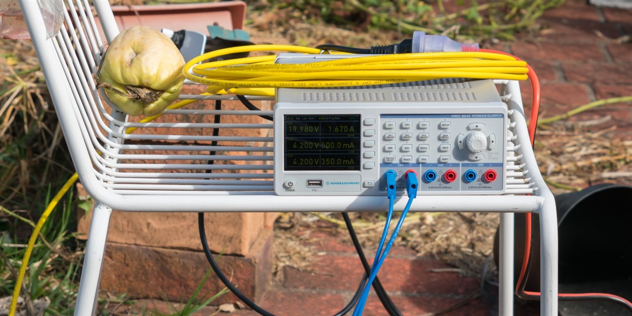
This test was performed outside for safety reasons. I used the Rohde & Schwarz HMC8043 power supply, initially using one channel, but later paralleling all three channels together for more current. I used a 30m Ethernet lead for remote control for better reliability.

Thick outdoor terracotta tiles were used as a test surface with a clear thermal signature. Thermal imaging was recorded with my Nokia G60 5G connected with the Xinfrared InfiRay P2 Pro USB-C thermal camera. The phone was attached to a tripod thanks to this 3D print design by neyfrota. A second tripod was positioned with a DSLR camera providing the visible video.
The results were quite varied – the EDLC only had a minor venting …
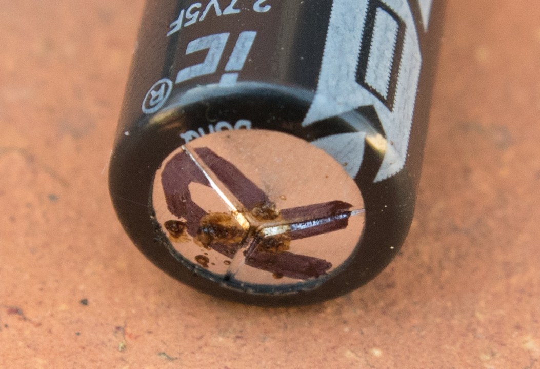
… with one LIC showing a more significant venting with a lot of smoke. Leaving the voltage applied allowed the whole thing to essentially “cremate” itself with melting of the rubber bung.
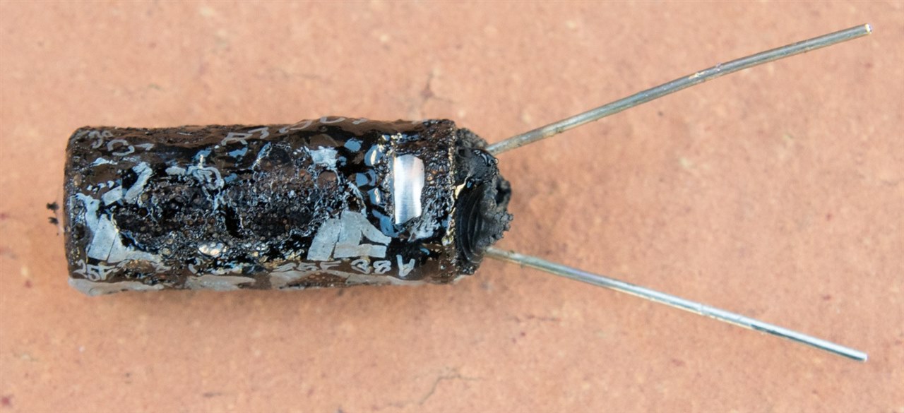
The final LIC …

… went full-on explosive. That is definitely a possibility with every component in a can, when the pressure builds much quicker than the vent can release (or if the vent fails to blister).

I call this meal “deconstructed supercapacitor, sans aluminium shell”. The bung and leads are visible with the connections to the foil. Pieces of paper, carbonised copper are also visible. The spiral construction appears very reminiscent of ordinary aluminium electrolytic capacitors.
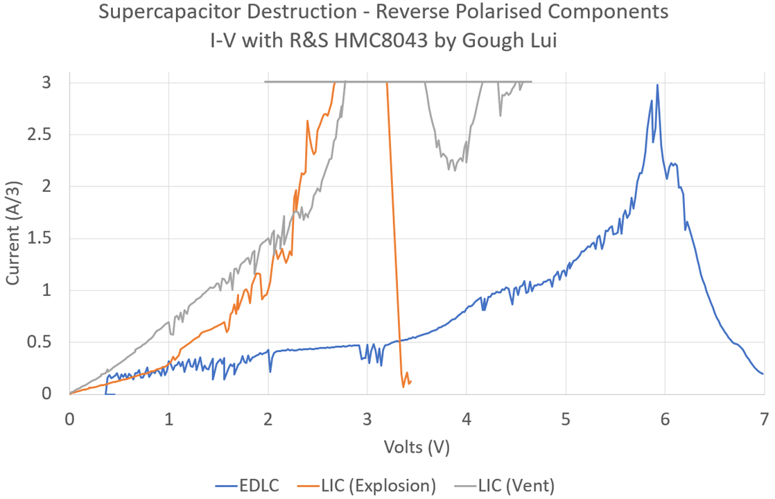
Looking at the I-V curve, it seems the current begins to take off around 3.5V for EDLCs. The LICs were both soft-shorted, so it was more like dissipating power into a resistor – but interesting to see both showed rather similar curves. Note that this is measurement only from Channel 1 of the power supply, but as three channels were in parallel, the actual current delivered is 3x the indicated number. Another thing is the “noise” in the plot is due to the channels “fighting” one another to deliver the current.
I did want to see what would happen to a coin-cell type EDLC as I suspected it would fail around the seals given a lack of a vent, but the last experiment happened to be quite loud and my neighbours were just starting up a housewarming event. I didn’t want to cause any trouble … or get myself into trouble … so I’ll call it quits while I’m ahead.
Q17: What’s Inside a 5.5V Supercapacitor?
Is there such a thing as a 5.5V supercapacitor cell? It’s a common voltage rating for memory backup applications. Cutting back the sheathing on some of them gives us the answer …
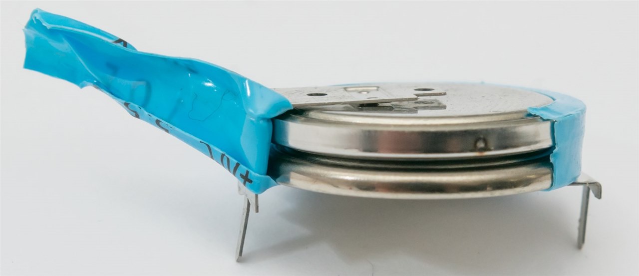
Turns out the EDC105Z5R5H (5.5V 1F) supercapacitor is made of two cells in series. In theory, this could be two 2.7V cells (5.4V) but that seems a bit close, so perhaps two 3V cells (6V) would be more likely. These must be well-matched cells that are quite stable, given that there is no balancing. I think this is good confirmatory evidence that balancing may not always be required.
But there are also PCB-pin mount cans like the EDS104Z5R5C (5.5V 0.1F) that don’t have an obvious ridge under the heatshrink to suggest they are two cells in series.
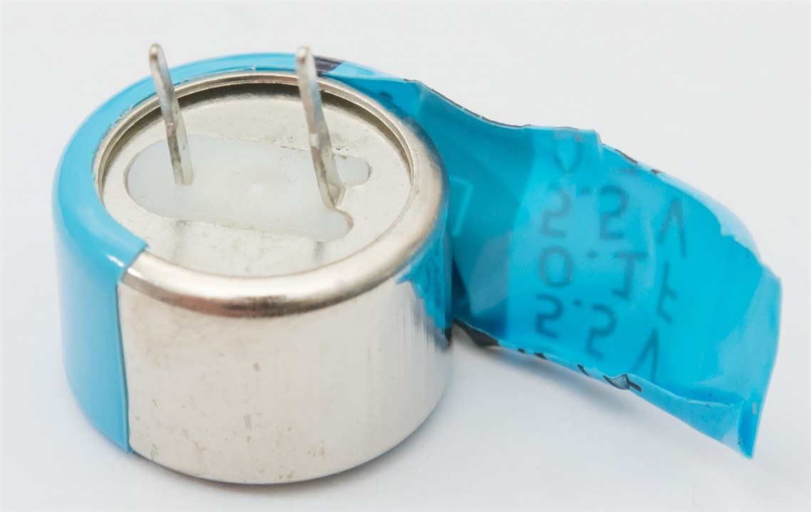
In fact, cutting away the heatshrink reveals a smooth-sided can. But I wasn’t so easily defeated … so I got out my side-cutters and started to nibble at the seam.
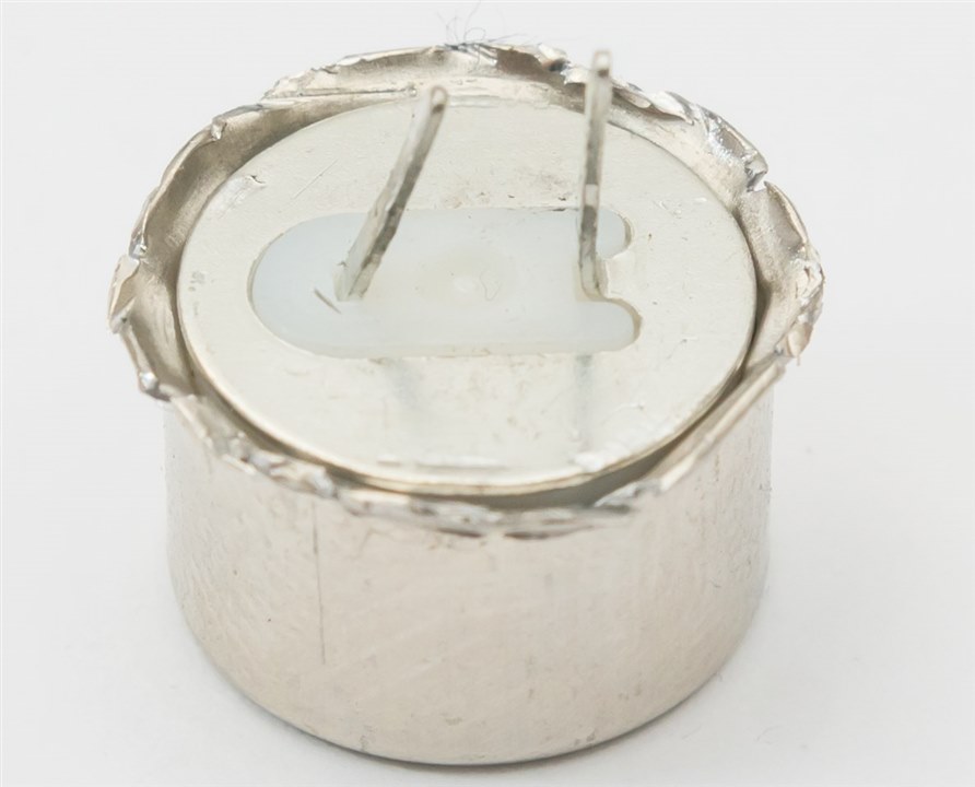
With a bit of a tug, the contents “sproinged” out onto my desk.
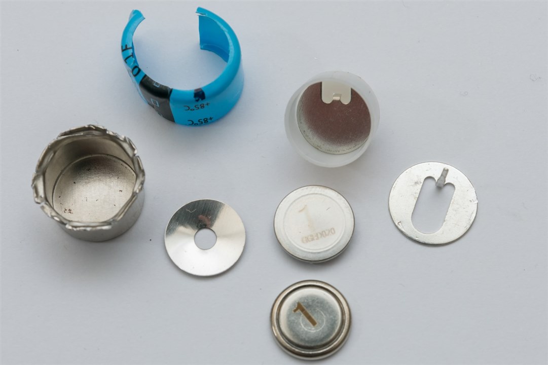
As it turns out – the metal can is just a mechanism to hold two supercapacitor coin-cells together in series by a “spring” disc applying pressure to the stack. The can forms one side of the cell, while the inner contact in the plastic insulating sleeve forms the other. The form may be different, having loose laser-marked cells (probably for matching) but functionally it is equivalent to the welded forms above.
Attempting to dig further was not productive – I couldn’t safely open the coin cells themselves but I did see a clear liquid coming out of one as it was squeezed in a vice. Nevertheless, I believe the construction to be as per this guide from Panasonic.
Q18: Can it be Used to Replace Coin Cells for Power Backup?
Let’s try to replace a CR2032 coin-cell power back-up with a supercapacitor instead. As part of my recent RoadTest on the Weller WXsmart Soldering Platform, I constructed a 7-segment LED clock kit. I found the CR2032 back-up to only last a fairly short time, as this kit is using the cell to keep the whole microcontroller running.
To understand the tolerance of this input to various voltages and to understand the current consumption, I used my Keithley 2450 SourceMeter to provide input to the CR2032 coin-cell input while the kit was being powered by the Rohde & Schwarz HMC8043.
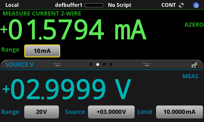
When the kit is unpowered, the microcontroller is taking a rather sizeable 1.58mA from the cell at 3V. This is because this is not a true RTC but it is instead powering a running microcontroller.
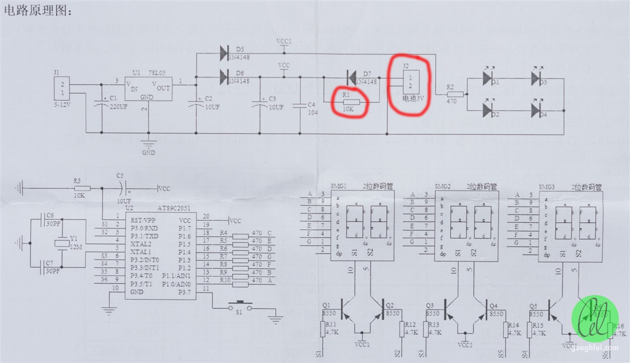
Looking carefully at the schematic, it seems clear that the battery is being trickled through R1 (10kΩ) which is a bad idea if it is a primary cell. But this suggests we can easily modify this for supercapacitor usage. To do this, I decided to simply remove the battery holder and change R1 to 47Ω to allow the cell to charge more quickly without overloading the 78L05 regulator. However, because of the design, there are a number of 1N4148 diode drops which limit the supercapacitor charging to about 4.38V and will waste some voltage when under supercapacitor use.
Based on this, if I choose the 5.5V 1F supercapacitor and run from 4.38V down to 2.55V based on an average current of 3.08mA (as more current is consumed at higher voltages), then the expected up-time is 9 minutes and 54 seconds excluding any voltage droop. This may not seem long compared to the months-to-years of an RTC-based solution, but keep in mind that this is running a whole microcontroller, then this is quite a good result. Definitely enough time to change power sources or to relocate the clock without losing time.
To its credit, the pin-spacing of the EDC105Z5R5H part matched the PCB CR2032 holder perfectly for a neat modification.
In practice, after permitting one hour of “soak” charging of the supercapacitor, the back-up time to 2.55V was 11 minutes and the time was maintained correctly. This is pretty close to estimates – likely because actual current as the voltage varied was not well accounted for.
Q19: What Happens Under Cyclic Charge/Discharge?
There is another lifetime defined by the datasheet which is cycle life. For Cornell Dubilier’s DGH series supercapacitor, a cycle is defined as a charge to working voltage for 20s, CV charge for 10s, discharge to half of working voltage for 20s, rest for 10s, all at 25°C. For the VMF/VPF LICs, this is only defined as a charge/discharge from 3.8V to 2.5V at 25°C. Typically claimed cycle life is in the 250,000 to 500,000 cycle region.
Based on this, the lifetime of a supercapacitor operated at the 1-minute cycle is up to 500,000 minutes or about 347 days. Unfortunately, I don’t have this time to do such a test.
For cycle-life torture, I decided to take a different approach and shorten the test a bit while also making it even more torturous. Using my Rohde & Schwarz NGM202 two-quadrant power supply and my self-designed banana to terminal adapter, I connected two DGH105Q2R7 (2.7V 1.0F) to the power supply, one to each channel.
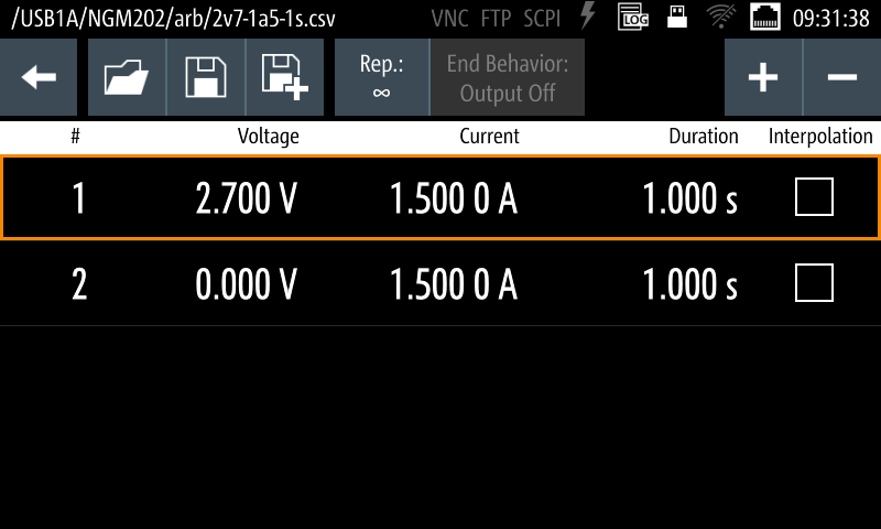
Using the internal QuickArb feature, I made a cycle comprising of 1s charging and 1s discharging in a loop. The left channel was set to 0.96A (the maximum 1s-current as stated by the datasheet). The right channel started off at 3A (the maximum the NGM202 could source and sink).
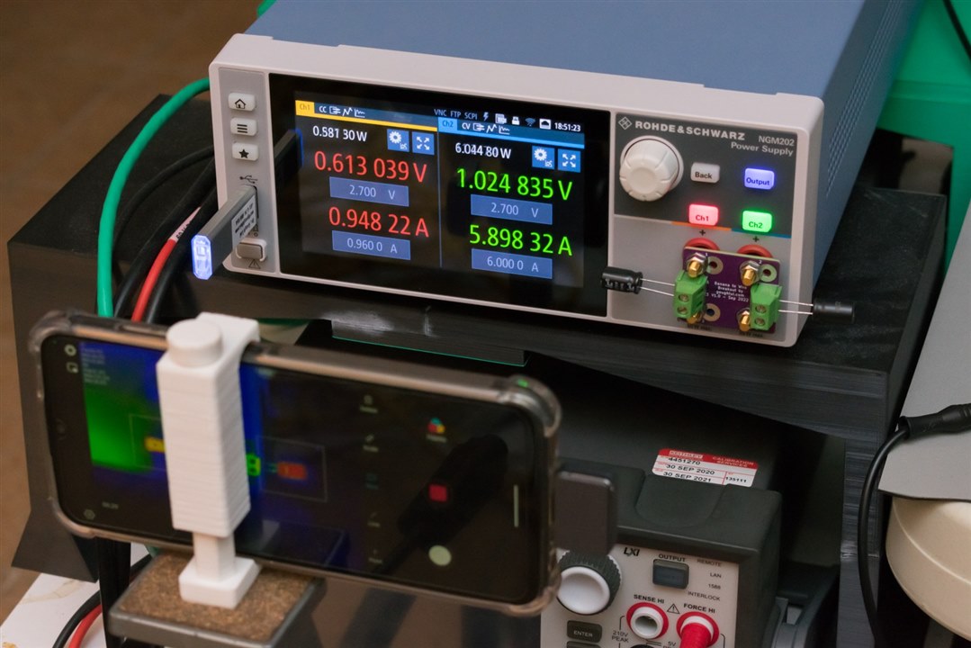
Observing the thermals with the Xinfrared InfiRay P2 Pro thermal camera revealed the following:
Under the rated 1s-current, the left capacitor rose to 36.5°C in a 21°C ambient, a 15.5°C temperature rise. Pushing the current up to 3A (which is below the short-circuit rated current) resulted in significantly more heat generation – reaching 132.5°C within eight minutes leading me to abort this test to avoid the potential for capacitor venting. Instead, I cut the current down to 1.5A which keeps the capacitor at a toasty 85°C and resumed the test. But even considering the fact that the capacitor may be rated at 1,500 hours at such temperatures, it would take 62.5 days to reach the “time” lifetime which is time I don’t have. Based on the 2s cycle time, 43,200 cycles can be completed in a day and the 500,000 cycle rating will be exhausted in 11.5 days.
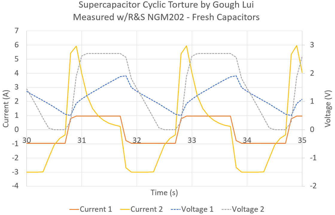
Initially, I was quite enthusiastic with #1 running at the 0.94A 1s-current rating and #2 running at 6A charge/3A discharge (at the limit of what the Rohde & Schwarz NGM202 power supply can do). With fresh capacitors, we can see that both capacitors easily reach the current limit at least for some portion of the charge. Sample #1 however doesn’t fully charge nor discharge at this current limit, so it “breathes” happily banging between positive and negative current limit.
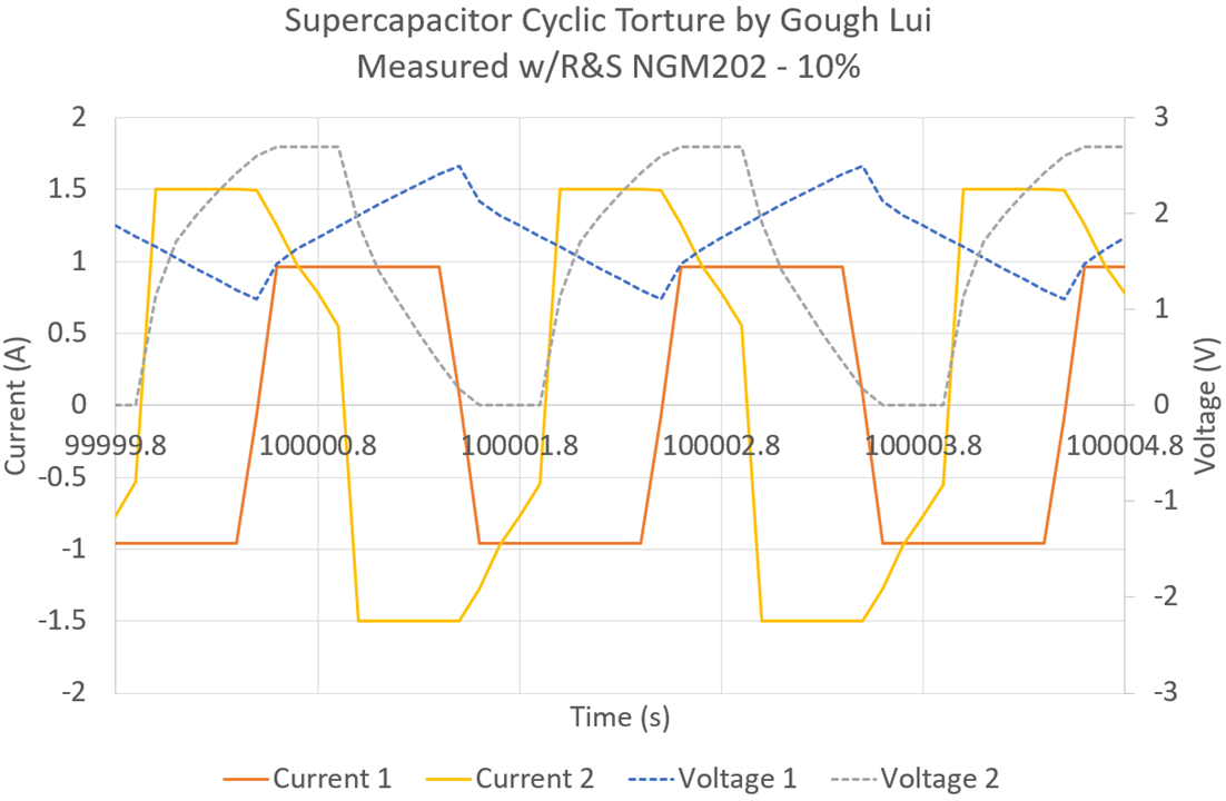
Around 10% in the test time, I have had to reduce sample #2 to 1.5A limit because temperature was reaching critical (likely-to-vent) levels above 130°C. With this decreased current level, it seems the capacitors is mostly (60%) constant-current charging or discharging.
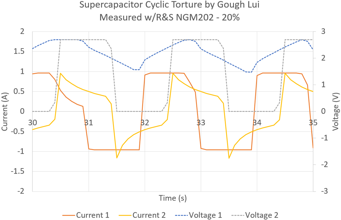
By 20% of the test time (ignoring the time scale as this is for each log file), Sample #2 cannot sustain even the 1s-current rating, suggesting an increase in ESR beyond specifications. Sample #1 continues to perform as expected, although possibly due to temperature/leakage/test-equipment effects, the voltage is now reaching the upper-limit suggesting charging is more efficient than discharge.
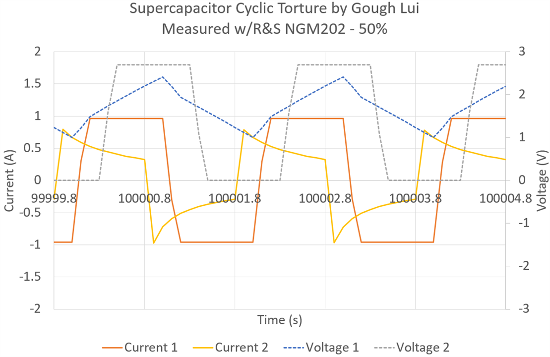
At 50% of the test time elapsed, Sample #2 is taken offline shortly after this reading is taken. The current sustained by sample #2 is now well below that of sample #1. Sample #1 has now reduced in voltage slightly which brings it back to “breathing” away from the voltage limits.
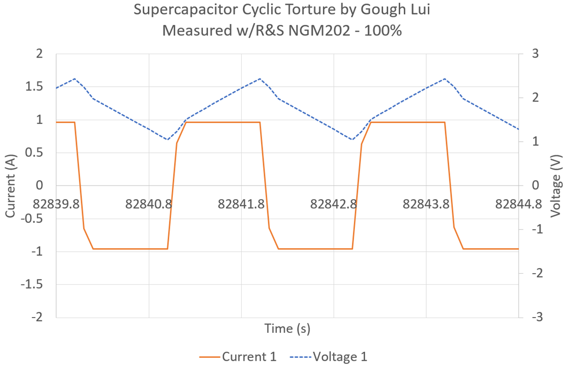
At the end of the test, we are approaching 476,880 cycles and the supercapacitor still is working well at constant-current in both directions. This impresses just how important it is to respect the specification limits regarding currents if you want to have the rated lifetime.
Q20: What Happens Under Repeated Short-Circuit?
In some applications where supercapacitors are used, high peak currents are a key characteristic and the temptation may exist to abuse them at near-short-circuit conditions. After all, datasheets do list short-circuit current while telling you not to expose them to short circuits, so I wonder what would happen?
Ferreting around my junk box, I found a very basic 9V DPDT relay from Tianbo that was rated at 16A. The 16A rating is a little wimpy compared to a supercapacitor’s short-circuit current rating, but paralleling the two contacts should help with the current carrying issue (but perhaps not contact wear as the contacts won’t have identical timings). I used short lengths of 16AWG silicone wire to carry the current while providing a back-EMF protection diode which was then connected to two 24AWG lengths of silicone wiring to “activate” the short using a second channel on the Rohde & Schwarz HMC8043 power supply.
To make my life easier, I crimped some 4mm bullet receptacles which I use with banana leads from the first channel to charge the capacitor. Bussing the connections together are three-way Wago 221-series connectors. I also set-up my smartphone with an Xinfrared InfiRay P2 Pro thermal camera to observe the set-up in case dangerous temperatures were being developed.
A simple script toggled between charging and shorting on a time-basis. Capacitors of different types were tested although no LICs were tested as they are not allowed to be bought down to 0V. Test candidates were DGH505Q2R7 (2.7V 5F Radial), DSF305Q3R0 (3V 3F Radial), EDC105Z5R5H (5.5V 1F Coin).
As the coin type had reflective surfaces, I put a square of black electrical tape on the surface to get more accurate thermal imaging results.
The results are quite interesting – in the thermal video below, the effect on short circuit on heating of the legs is clearly visible as a cyclic pulsation (3s charge, 2s discharge for radial, 17s charge, 3s discharge for coin):
However, it seems that such torture is quite difficult on the supercapacitors and clear changes in characteristics occur relatively quickly. In around 6,852 cycles, DGH505Q2R7 managed to swell and dome its vent.
In just 45 cycles, close monitoring of DSF305Q3R0 was able to detect significant differences in the charging characteristic which suggested ESR increase. For this test, I actually fitted a Holdpeak HP-605C current clamp around a lead and used the Rohde & Schwarz MXO4 (under review) to measure the short circuit current -
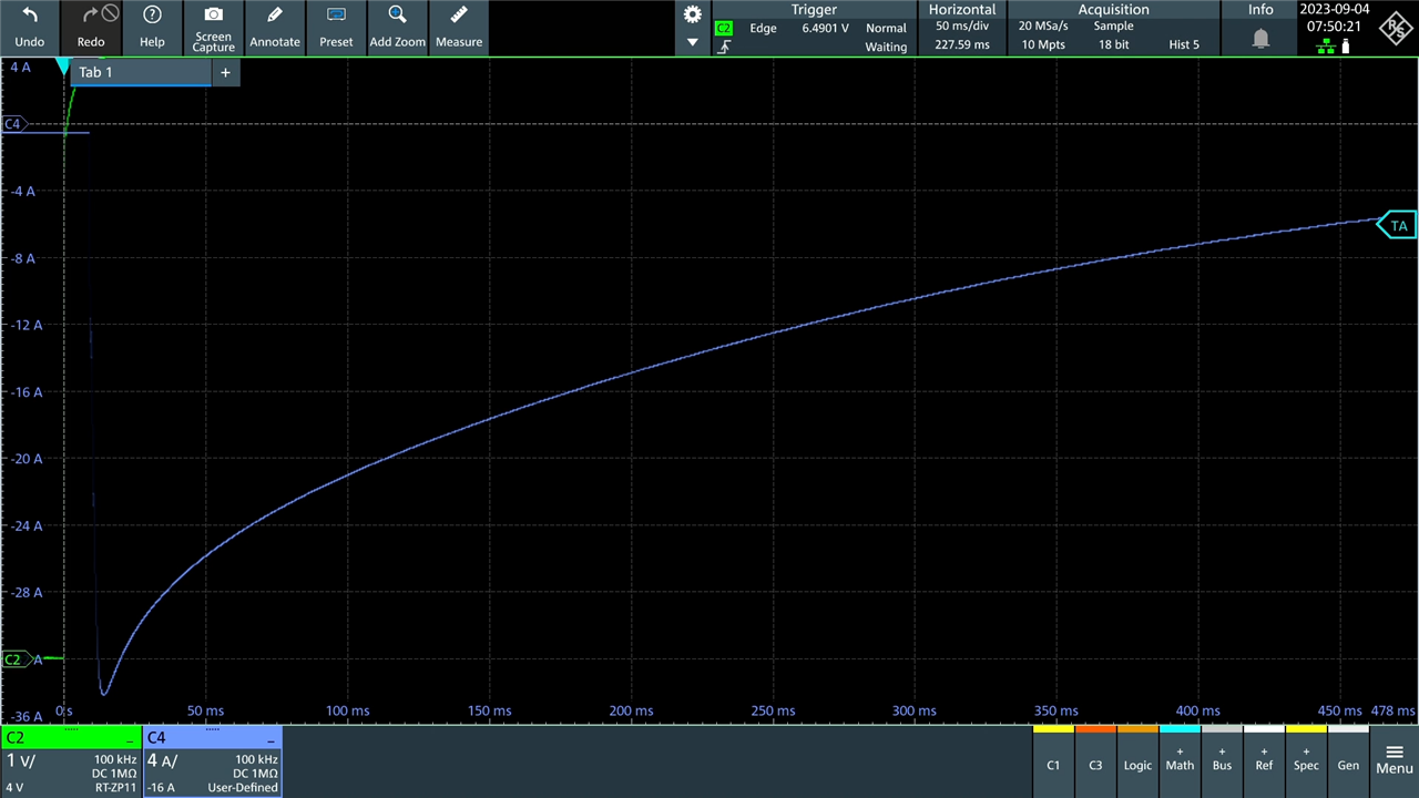
Initially, around 35A short circuit current was observed, but just five cycles later …
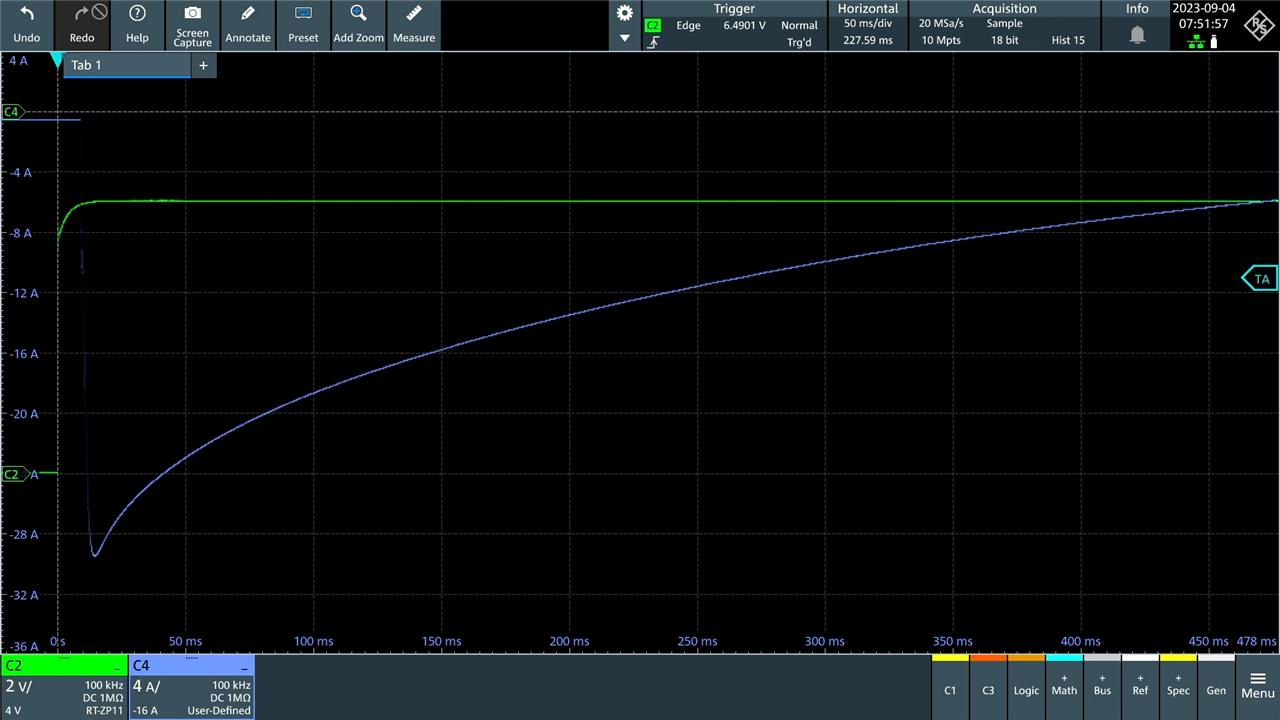
… it fell to about 29.5A. This could be a temperature-related effect or an actual ageing effect – but as the previous tests ran for excessive numbers of cycles, I terminated this one earlier to see if the effects occur even after a modest number of short-circuits. Notably this is still significantly higher than the datasheet claimed short-circuit current of 20A.
However, cyclic shorting of EDC105Z5R5H on a slower cycle managed over 13,000 cycles without any noticeable change in characteristics. This may be because of its intrinsically higher internal resistance being protective by limiting peak current and associated temperature rises.
The aggregate results for both cyclic current and cyclic short-circuit torture is summarised below:
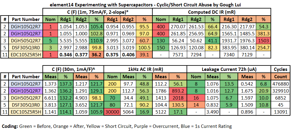
The key changes visible in end-of-life supercapacitors include a drastic increase of DC internal resistance to above twice nominal values and AC internal resistance increases. That being said, it seems the DGH105Q2R7 that was operated within its 1s current ratings survived 476,880 cycles (close to the 500,000 cycle rating) without significant change in characteristics aside from a small reduction in effective capacitance within its ratings.
Leakage currents were interesting – the supercapacitor cycled within its 1s-current ratings actually improved its leakage by almost half. The coin-cell supercapacitor subjected to cyclic shorts also improved its leakage by over three-fold. This phenomenon is not unheard of. The others, however, showed an increase of about 50% in leakage current.
Q21: Building a Solar-Powered LoRaWAN Particulate Monitor Sensor
This was the main application which I proposed that would make use of the included supercapacitors and small solar panel. Building upon my design from the Save the Bees Design Challenge, I wanted to take the lithium-ion batteries and large solar panel out of the equation and replace them with the supercapacitors and small solar panel. Such a set-up would be space-saving but might also last longer as battery cycle life and tolerance for extremes is quite limited. The downside is that there won’t be any operation without sunlight …
Ideally, if I were to properly design a system to maximise use of solar power for a sensor application, I might consider implementation of maximum power-point tracking on the solar panel to maximise power generation. I would also have a very low quiescent switching converter with a wide input voltage to generate stable output for the sensor to avoid voltage-related errors and increase the usable voltage range of the supercapacitor. I might also have a power supervisor to generate a power-good signal to avoid the microcontroller from powering up without sufficient charge or to hold it in reset when the charge dips below an acceptable level. It might also have a voltage-window for use with LICs to avoid over-discharging them as well. Because of the voltage required, it will require two supercapacitors in series, so an active balancing circuit might be nice too. However, there isn’t really the time to source and design such a complex solution, so I opted to go simple instead.
As the system is based around the Arduino MKR WAN 1310, power is handled by a BQ24195L. Looking at the datasheet, this solution can handle an absolute maximum of 6V on its battery input, even though it is designed for a lithium-ion battery of up to 4.2V when charging. As I won’t be using the BQ24195L to charge, this won’t be an issue and the solar panel’s 5.7V open-circuit voltage is within the capability which is nice.
To charge the supercapacitors, I’ll be using the solar panel. While I could connect it directly to the power bus, the solar panel was measured to have about 300µA leakage when it has a lower voltage than the bus. This “dark current” is a known phenomenon related to the quality of the cells and to prevent it, it is customary to use a low-leakage diode. I used a 1N4004 in-series with the solar input, which has the side effect of bringing the input voltage down to around 5.05V. There was no need for any current-limiting resistances for the supercapacitors, as the solar panel is a current-limited source well-within the limits of the supercapacitors chosen.
For power storage, I decided to settle on using two 3V 7F supercapacitors (DSF705Q3R0) in series to give a 6V 3.5F-equivalent supercapacitor. As I won’t be using any balancing, I discharged all capacitors and kept the leads shorted for an hour to ensure they were “empty” before commencing. With an expected 5.05V maximum, there should be enough headroom to operate without balancing.
The next thing to be concerned about is what happens when the voltage falls down as the supercapacitors discharge. The BQ24195 used by the MKR WAN 1310 is designed to keep the lithium-ion battery safe from overdischarge, so it should be stable down to that voltage. Unfortunately, below this, we cannot operate and the energy in the supercapacitors cannot be used. Another thing to think about is whether the unit will wake-up when voltage is applied, as it could be non-monotonic and unstable. Apparently, the datasheet claims that it will come up as long as the voltage rises above VBAT_DEPL which is 2.4V typical + 0.17V hysteresis. As a result, it will come back to life if the “battery” (ahem, supercapacitor) is externally charged outside of the BQ24195. Within the operating range, the BQ24195 keeps the Arduino’s internal voltage rail stable at 3.8V which is then linearly cut down to 3.3V for the microcontroller.
In many ways, because of the behaviour of the BQ24195 is the saviour here, making such a simple modification possible –
However, there are still issues to contend with – radio transmissions require quite a bit of power and so there is a risk that the unit can “come up” without sufficient power to complete a transaction, resulting in wasted airtime with the unit repeatedly making incomplete transmissions and maybe even resetting in a loop. As a result, I modified the code to measure the voltage from a 1k/1k2Ω voltage divider to determine if there is enough charge to commence.
Prior to putting this into action, I checked the current consumption behaviour with the Keithley 2450 SourceMeter –
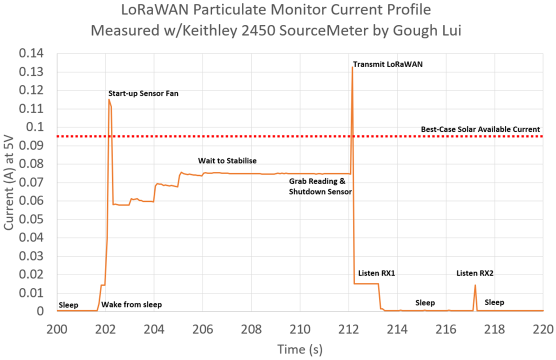
We can see that the current peaks well-exceed the 95mA best-case power from the solar panel. This would cause a serious brown-out on the rail which is likely to result in the unit resetting continuously.
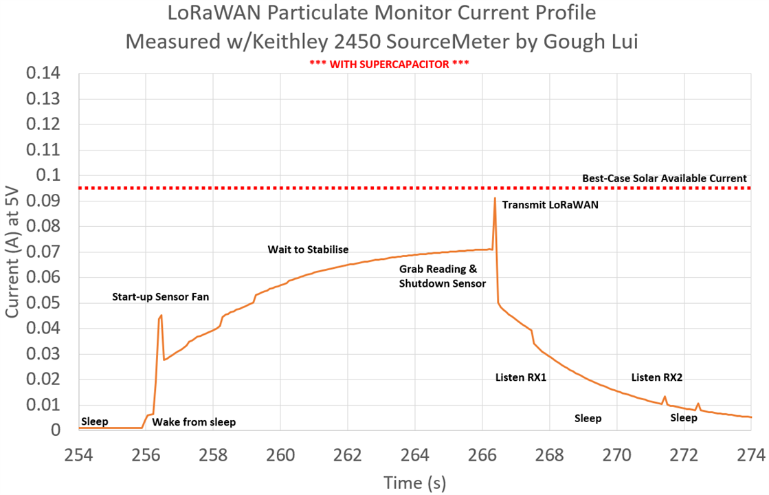
Just installing the supercapacitors, we can now clearly see that we are below the 95mA threshold, as it uses up the stored power in the supercapacitor to service the larger peaks and takes current to charge the supercapacitor when the system isn’t drawing as heavily. Of course, in reality, the difference is much more drastic as the voltage rails are allowed to swing a little. So in reality, one can perhaps still operate with a current-limited supply that has closer to the full-cycle average current.
Nevertheless, assuming we need about 75mA for 12s and 0.878mA for 300s of sleep for a transmit cycle, how long will our supercapacitor solution last? Each transmission cycle requires 5.817J of energy, while the supercapacitors will hold 11.83J from (5.0V down to 2.4V) so it has enough energy on a full charge to handle two full transmission cycles (ten minutes). This means that clouds are not a big issue for us!
So outside it goes – under a protective canopy of a plastic tubs weighed down by terracotta tiles.
The catch-22 of particulate monitor sensors – they have to be exposed to air to get good readings, but this could lead to them being exposed to liquids which could kill it. While I didn’t expect it, we had a few days of very strong winds and a day of rain too …
… but the system lived!

Every morning, I am watching The Things Network to see my device join the network and start transmitting messages. Often it will join under weak sun, then inhibit a few transmissions as it waits for its supercapacitor to charge back up. But just like the Mars Rover, my probe is “phoning home” whenever it can!
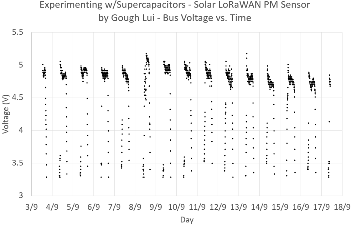
It has now been in operation for 15 straight days! Looking at the bus voltage, considering I’m using low-quality 5% carbon resistors which might drift in the sun, it’s quite clear that most days, we’re able to get a pretty stable voltage in the sunny part of the day with a slight decline as the tilt of the panel may not be ideal. The key outlier is 8th September which was a cloudy and rainy morning, hence the scatter and the fact it woke up later that day. Some cloud-lensing effects are likely too, explaining the voltage increasing above the level of clear days.
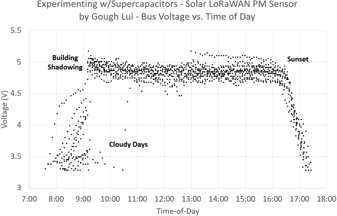
Plotting it based on time, we can see how the building shadow affects the wake-up of the system, which is getting earlier on a daily basis as we approach summer and our days are lengthening in Sydney.
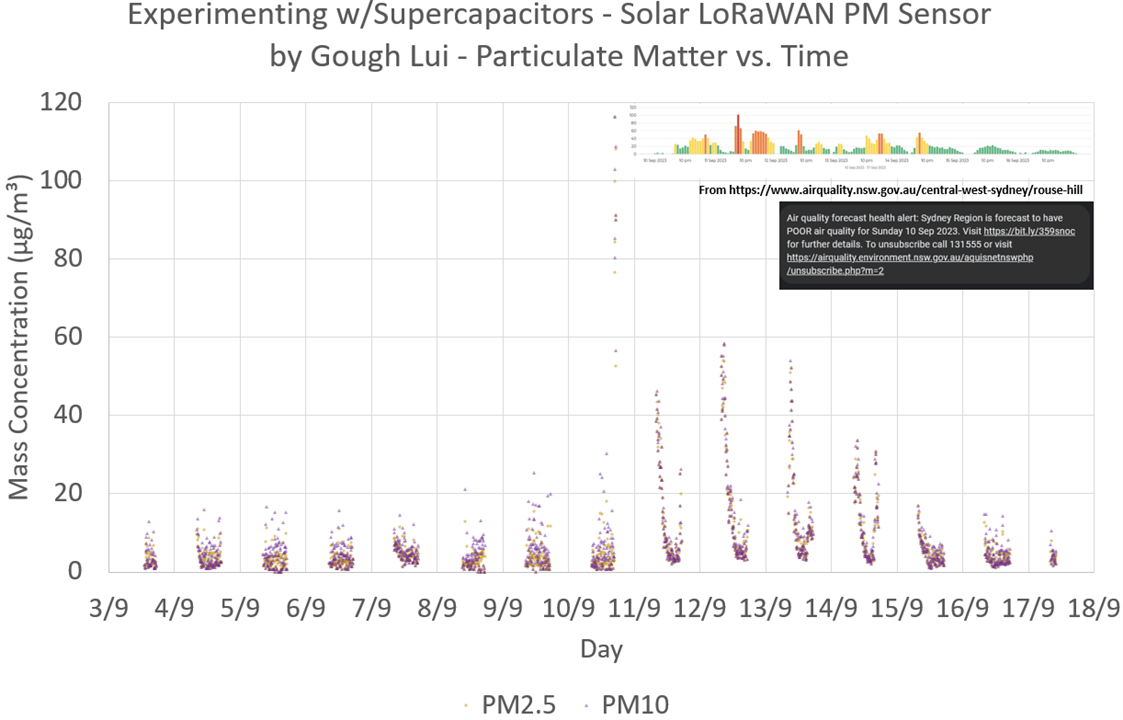
We get a nice scatter of PM values – of course, the use of a sensor like this is potentially problematic as it may reset before it ever gets to self-clean. But it’s clear that there are some trends with days that are elevated because of local back-burning operations. This correlates quite well with nearby local government air-quality sensor data. This indicates that the system is a success!
Q22: Series-Connected Supercapacitor Imbalance in Practice?
So far, I have made the assumption that no balancing was necessary based on the headroom in voltage ratings. But was this actually the case? Let’s first start with a practical experiment.
I chose to run this experiment on two DGH106Q2R7 (2.7V 10F) and two DSF256Q3R0 (3.0V 25F) supercapacitors as they were the only radial supercapacitor pairs I had that were not otherwise occupied. The capacitors were discharged and then shorted for an hour.
Then, using jumper wires, I configured them in series and then applied 5V at 1A to the set for four hours. Afterwards, the voltage was disconnected and the voltage across each capacitor was measured using a Keithley 2110 5.5-digit DMM. The results are presented below:

It seems that the first pair might not have been as close as the numbers suggested – they had a difference of 130.1mV between the two capacitors. The second pair was much closer, having just 2.5mV difference between the pairs even though the test figures didn’t seem to suggest that they would be that close. From this practical experiment, it seems that the amount of headroom required is in the order of a few hundred millivolts.
But let’s take a more mathematical approach of worst-cases. For a hypothetical radial supercapacitor of 1F, given +/- 20% tolerance, one may be 0.8F while the other is 1.2F. If we put the two in series and apply 5V, they will reach 2V for the 1.2F capacitor and 3V for the 0.8F capacitor – a discrepancy of 1V. If this was a 3V capacitor, then might appear just acceptable, but it could be worse due to mismatches in leakage current.
Thus, the use of balancing may improve solution lifetime and avoid uneven stresses. Such a solution does, however, add complexity and power consumption so may not be feasible in all circumstances.
Q23: How do Supercapacitors Perform in Low Temperatures?
The cold is an enemy of many forms of energy storage. When it gets cold, batteries often under-perform – whether this is a digital camera refusing to run, a car that cranks slowly or a flashlight that acts dead. But what happens to supercapacitors?
Exploring this extreme, I prepared supercapacitors in food-safe containers with water …
… threw them into the freezer for a few days, then hooked them up to be tested for their characteristics while in an ice-water bath.
The results are summarised in the table below:

It would appear that being cold doesn’t affect the capacitance values of EDLCs significantly, however, LICs do lose a notable amount of capacitance. The biggest influence, however, appears to be for DC internal resistance which increases noticeably. Despite the larger percentage increases in DC internal resistance for EDLCs, the resistance of cold EDLCs are still lower than that of the LICs tested. So it would appear that they are not entirely immune to low temperatures, with the increased internal resistance resulting in a voltage “droop” under load.
Q24: Practical Use of LIC Supercapacitors in a LED Blinker
Finally, I decided to use some of the LIC supercapacitors which have an uncommon 3.8V nominal voltage and have a minimum 2.5V or 2.2V voltage which requires additional care in implementation. I decided I would build an LED blinker which acts as a bit of a beacon. Aiming for low power, I opted to use a Digispark board based on an ATTiny85 with its onboard diagnostic LED as my beacon.
Only wanting a low duty cycle, I was happy with a 16ms blink every 8s, so I set my mind to letting the microcontroller sleep at all other times. Clock sources would be internal – the slower the better. As time was running out, I didn’t have much time to optimise the set-up. The code was based on Watchdog Timer sleep code from Donal Morrissey which I modified (in haste) to run on a Digispark with circuit modifications from btidey’s Reducing Sleep Current in ATTiny Digispark Instructible.
To handle charging the supercapacitor and protecting against overdischarge, I decided to go with the venerable TP4056 and DW01 combination module I previously used in the Save the Bees particulate monitor (as that is no longer needed there anymore).
The only reason I can do this is that the charge voltage is capped at 4.2V which matches the surge voltage of the LIC supercapacitors. While this is not friendly to the capacitors’ lifetime and is a surge (not continuous) rating that won’t hold at higher temperatures, it shouldn’t cause outright failure of the capacitors either and requires very little implementation effort. The DW01 will adhere to the 2.5V minimum voltage quite reliably.
Construction took place on a scrap of Veroboard on the bench – the size just happened to be about right. Because of the modifications, it is not allowed to plug in the Digispark USB to a USB port, otherwise 5V will be applied to the LIC supercapacitors. Nevertheless, it was possible to get it to blink, but a key consideration during construction was to solder while avoiding short circuits! It is the first time I’ve had to solder a live-circuit and it was a bit tricky to do.
Not satisfied with having just two LICs, I decided to push for three. Because of the size of the “scrap” of Veroboard that I used, I had to be a little creative and unorthodox with strategic bridges and wires coming out of the edge of the board. While messy, it does work!
On completion, I covered the back in hot-glue to avoid any accidents. While the supercapacitors themselves might total 120F at up to 4.2V at a full charge, the current they can deliver can be quite destructive. I managed to get a small pop from a momentary contact with a wire fragment on the bench!
But thinking about this more from a battery point of view, 4.2V 120F with a discharge down to 2.5V would give an equivalent capacity of 56.7mAh which is about the same as what you might find in a true wireless stereo Bluetooth earbud! As a result, it doesn’t have the energy density that such a battery may have, but it does have the speed – charging this blinker takes all of two minutes, tops!

How long does it run? Well based on testing the cycle-based consumption, it seems it has an average current just shy of 0.2mA, but can only operate down to 3.0V. This suggests we can get a bit more than eight days of operation from a single charge – not great, but not bad either, noting that small errors in current measurement can sway this either way by a significant margin. After a week, it was still running, although noticeably dimmer.
Conclusion
A supercapacitor is a component that stores energy with a capacity, cycle life, energy density and power density somewhere in-between ordinary capacitors and batteries. It is most useful in burst power applications with time constants of no less than 1-10s through to longer time memory back-up applications. Individual cells typically have voltages of 2.7V or 3.0V (EDLC) or 3.8V (LIC) requiring multiple cells to reach capacity and voltage requirements. Due to mismatch possibility, balancing circuits may be necessary to ensure safety and longevity. Traditional supercapacitors are EDLCs which store energy electrostatically, making them faster to respond with lower internal resistance. Hybrid supercapacitors (LICs) borrow an anode from lithium-ion batteries which increases energy density significantly, but at the cost of having a voltage “window” they must operate within (2.2V or 2.5V to 4.2V), being more temperature sensitive and having a higher ESR than their EDLC counterparts.
Compared to traditional wet electrolytic capacitors, it seems their rated lifetimes and temperatures are lower. The chemicals contained within are perhaps part of the cause, although lifetimes can be managed through careful derating of voltage, keeping within current limitations and controlling ambient temperature. While EDLCs seem to handle reverse polarity, LICs cannot. Furthermore, LICs arrive pre-charged and cannot be shorted at all. It seems also that LICs are somewhat more violent with regards to venting, if they do fail.
Nevertheless, it was possible to apply them to a solar-powered LoRaWAN particulate monitor sensor of my own, to replace a battery backup in a 7-segment LED clock kit through modification and to an LED blinker of my own design.
In all, in the name of science and discovery, I’ve researched, used, charged, discharged, cycled, over-stressed, over-heated, reverse-polarised, over-voltaged, vented, exploded, short-circuited, frozen and torn-apart the supercapacitors I’ve been given. That was a lot of work, especially given the time.
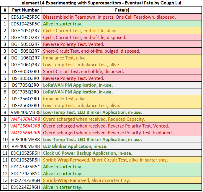
In the end, there are not many supercapacitors still left healthy in the kit, but at least I can say I’ve made good use of most of them. Through this “experimenting with” design challenge, I’ve been able to answer almost all the questions I had in mind about supercapacitors and I feel much more confident about applying them to my future designs, should the need arise.
I hope you enjoyed my series of blog posts and that they were informative. I hope you too have learned about supercapacitors and thanks again to element14 and Cornell Dubilier Electronics (CDE) for this opportunity.
Appendix: Acknowledgements
A special mention goes out to all of the major test and measurement equipment and miscellaneous tools that I’ve involved in my experiments (many of which I have reviewed), without which, my experiments would have been much more difficult to conduct. I am most fortunate to have such a reliable suite of equipment at my fingertips, willing to answer any question I have at any time of day or night.
A special thanks to:
- Keithley 2450 SourceMeter Source Measurement Unit
- Rohde & Schwarz NGM202 (Two-Quadrant) Two Channel Power Supply
- Rohde & Schwarz HMP4040 Four-Channel Power Supply
- Keithley 2110 5.5-digit Digital Multimeter
- B&K Precision BA6010 Battery Analyser
- Agilent U1733C Handheld LCR Meterl
- Rohde & Schwarz MXO4 Oscilloscope (in review)
- HoldPeak HP-605C Current Clamp
- Fluke 279 FC iFlex True RMS Thermal Multimeter
- Xinfrared InfiRay P2 Pro Thermal Camera
- Multicomp Pro BAL1 0.001g/50g Precision Scale
- Weller WXsmart Soldering Platform
- Anycubic i3 Mega Pro 3D Printer
- Nikon D3500 DSLR Camera with Tamron 17-50mm f/2.8 Lens
- Mikrotik Knot LR9 LoRaWAN Gateway Router
- DFRobot LattePanda Delta 864
Of course, there are plenty of other pieces of equipment and consumables involved that could not be individually acknowledged, although I would also like to pay respects to my Lenovo E431 ThinkPad Edge which failed during the course of this “experimenting with” design challenge after eight years of service across six countries.
[[What’s Super about Supercapacitors: Blog Index]]
- What’s Super about Supercapacitors? – Part 1: Me and the Kit
- What’s Super about Supercapacitors? – Part 2: Types, Vendors, Safety & Specifications
- What’s Super about Supercapacitors? – Part 3: Measuring Capacitance & ESR
- What’s Super about Supercapacitors? – Part 4: Measuring Leakage, Sizing a Solution & Lifetime
- What’s Super about Supercapacitors? – Part 5: Safety Under Abuse & Power Back-Up Application
- What’s Super about Supercapacitors? – Part 6: Solar LoRaWAN PM Sensor, Low-Temps, Imbalance, Cyclic & Short Circuit Life, LED Blinker
- What’s Super about Supercapacitors? – Part 7: Quite a lot, actually! (Final)


Top Comments