


The DockBot is my take on a concept vision-guided robot that goes to the charger, picks up a mock charging handle, and then moves to the car and plugs it in. I will simulate this with a fixed external camera and two printed Aruco marked targets standing in for a charging station and a parked car: the robot drives itself to the first target on vision feedback alone, uses its hand mechanism to grab a mock charging handle there, then drives to the second target and reaches out to physically touch the marked point on it - standing in for the connector actually plugging in. No fixed charging pad, no precise parking requirement - the robot finds each target and corrects for wherever it actually ended up.
This post is a self-contained account of the whole build - concept, hardware, vision pipeline, motor control, the docking algorithm, and the mistakes along the way - written to stand on its own. For more details, do read through the individual posts.
- DockBot - Part 1 - The Concept
- DockBot - Part 2 - Positioning with Aruco Markers
- DockBot - Part 3 - New Plan, New Hardware for Better Sensing
- DockBot - Part 4 - Getting the Arduino Q to move the tank motors
- DockBot - Part 5 - The Mechanical Hand
- DockBot - Part 6 - The Mostly Open Closed Loop Control
The concept
A target - in the real version, a parked car; here, a box with a printed marker on it - sits somewhere in view of a fixed camera. The camera identifies the target, works out where it is, and once it's judged stationary, a tracked robot drives itself over using nothing but that camera's feed, stopping at a standoff distance in front of the target and reaching out with a small hand mechanism to make contact - standing in for a connector actually plugging in.
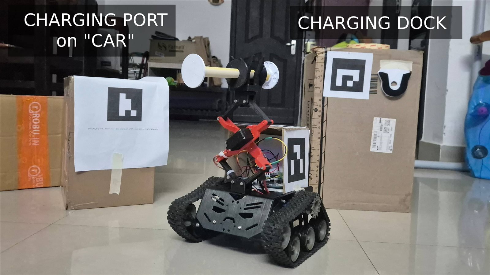
The core engineering problem is that the robot's on-board sense of "where am I and which way am I facing" is entirely absent - there's no IMU, no wheel encoders (yet), and the camera is not mounted on the robot. Every bit of positioning has to come from a fixed, external viewpoint watching two things at once: a marker on the target, and a marker on the robot.
Hardware
| Part | Role |
|---|---|
| DFRobot "Devastator" tracked tank chassis | mobile base, 2 BO motors, differential steering |
| Arduino UNO Q | robot's onboard controller |
| Radxa Q6A (Qualcomm QCS6490, 8x Kryo 670, Hexagon NPU) | vision/positioning, watches the scene from a fixed external position |
| Waveshare IMX335 USB camera | 5MP, feeds the Radxa |
| DRV8833 dual H-bridge driver | drives the two BO motors |
| 3500mAh 2S 7.4V Li-ion battery | power, via a buck converter down to the motors' 6V rating |
| 1x hobby servos | the "hand" - a lift mechanism |
| Printed Arucoo markers (DICT_4X4_50) | one set on the target, four (as a cube) on the robot |
The Devastator chassis replaced an earlier plan to repurpose an old 3D-printer gantry as a fixed-position arm - dropped mostly because the printer still gets used as a printer, and a mobile robot forgives imprecise target placement in a way a fixed gantry never could. The Radxa replaced an initially-borrowed Raspberry Pi for a similar reason (it was needed back for its actual job running a 3D printer's firmware), and turned out to have a real advantage anyway: a dedicated NPU gives headroom for heavier vision workloads later without changing the architecture.
System architecture
The controller is split across three processors, each with a genuinely different job and a different timing regime
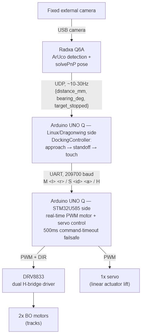
The Radxa runs the Aruco pose detection script. It has the processing power to handle it at roughly 20fps, and though not ideal, works for our project. Also, if a frame arrives a little late, the guidance is a little stale, no big deal. The STM32, on the other hand, runs the motors via the DRV8833 Divers, and that side can never be allowed to just hang - so it runs bare-metal, if it hasn't heard a command in 500ms, it cuts the motors, full stop, regardless of what the Radxa or anything else is doing. The Linux of ArduinoQ side sits in the middle making the actual decisions - when to approach, when to stop, when to reach out and touch the target - and it plays the same safety game one level up: if the vision feed goes stale for even a second, it halts the robot itself, before the STM32's own failsafe would ever need to catch it. It also gives me a Web UI to allow for stopping the robot if I ever need it.
The UART link between the two Arduino Q processors uses a deliberately tiny line-based ASCII protocol:
M <left> <right>   set track motor speeds, -255..255 each
S <id> <angle>     set servo <id> (0 or 1) to <angle> degrees, 0-180
H                  halt (motors only, servos hold position)
and UDP guidance message from the Radxa looks like:
{"type": "target_pose", "distance_mm": 850.3, "bearing_deg": -4.2, "target_stopped": true}
The Marker Detection Pipeline
Aruco markers
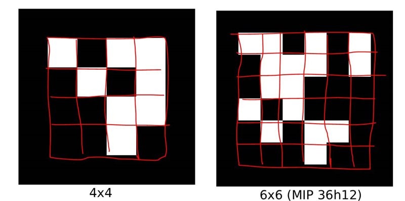
Aruco markers are square fiducial tags - a thick black border around a binary pattern that encodes a unique ID. OpenCV has native detection and pose-estimation support for them. The appeal for this project is that a single marker, once the camera is calibrated, gives you a full 3D pose (position and orientation) in one detection. Markers are organized into dictionaries - fixed sets of IDs with a given grid density and error-correction budget. This project settled on DICT_4X4_50 (4x4-bit grid, 50 possible IDs) after starting with a denser 6x6 dictionary inherited from a calibration board found online. The tradeoff is bits-per-marker versus reliability at range and blur tolerance: a 4x4 grid packs the same ID space into fewer, larger cells for a given physical marker size, which matters once markers are further away or slightly out of focus.
Camera calibration
Every lens introduces distortion, and cv2.solvePnP's pose output is only as accurate as the camera intrinsics feeding it. Calibration solves for a camera matrix and distortion coefficients by showing a known flat target - a chessboard, in the final pipeline - to the camera from many angles. This allows the camera to locate the position and pose of a marker of known size.
camera_matrix, dist_coeffs, image_size = load_calibration("calibration/camera_calibration_1280x960.npz")
You judge how good a calibration is by its reprojection error - basically, how far off the model's predicted corner positions are from the corners it actually detected, in pixels. Under about 1px is considered good. This calibration came out to 0.44px at full sensor resolution (2592x1944) and 0.23px at a downscaled 1280x960 - but that's a bit of an apples-to-oranges comparison, since fewer pixels means each one covers more real-world angle. Once you convert both to angular error instead of raw pixels, they're nearly identical (0.000217 rad vs 0.000227 rad, about 5% worse at the lower resolution). For that small a penalty, 1280x960 gets roughly double the frame rate and noticeably steadier tracking - and since the target in this project moves instead of holding still for a photo, that made it the easy choice for the default capture resolution.
Separately, floor-tile range/accuracy testing (marker placed at known 60cm intervals) found reliable detection out to about 6m, with position error growing from roughly 3-4% under 2m to a worst case of about 8% (average 5%) by 5m - well inside the ~5m range actually needed for a docking approach.
Pose estimation and the OpenCV 5 migration
OpenCV 5 removed cv2.aruco.estimatePoseSingleMarkers entirely, along with reshaping how chessboard corners are returned ((N, 2) instead of the old (N, 1, 2)). Every pose call in this project now goes through cv2.solvePnP directly, using SOLVEPNP_IPPE_SQUARE - the solver purpose-built for a single planar square of known size, which is exactly what an Aruco marker is:
MARKER_OBJECT_POINTS = np.array([
    [-MARKER_MM / 2,  MARKER_MM / 2, 0],   # top-left
    [ MARKER_MM / 2,  MARKER_MM / 2, 0],   # top-right
    [ MARKER_MM / 2, -MARKER_MM / 2, 0],   # bottom-right
    [-MARKER_MM / 2, -MARKER_MM / 2, 0],   # bottom-left
], dtype=np.float32)

corners, ids, _ = detector.detectMarkers(gray)
for marker_corners, marker_id in zip(corners, ids.flatten()):
    img_points = marker_corners.reshape(-1, 2).astype(np.float32)
    ok, rvec, tvec = cv2.solvePnP(
        MARKER_OBJECT_POINTS, img_points, camera_matrix, dist_coeffs,
        flags=cv2.SOLVEPNP_IPPE_SQUARE,
    )
    x, y, z = tvec.flatten()          # marker position in camera-frame mm
tvec gives the marker's 3D position relative to the camera (X right, Y down, Z depth - the usual OpenCV camera-frame convention); rvec, converted via cv2.Rodrigues, gives its full 3D orientation. That orientation turned out to matter as much as the position, later on.
Electronics and real-time motor control
For Arduino UNO Q programming, I'm building on the work from the last design challenge - On the Line - where I disabled the bridge between the Dragonwing Linux side and the STM32, giving the STM32 full bare-metal control instead of going through the Arduino sketch layer. Same STM32CubeMX HAL project setup carried over, pins reassigned for this board. For now I'm deliberately skipping the encoder and any PID control. I also added a 500ms command-timeout fail safe in STM32 firmware - if no valid line shows up within that window it halts the motors on its own, so a crashed Linux-side process can't leave the tank driving into something:

void UartProtocol_Poll(void)
{
  if (s_line_ready) {
    s_line_buf[s_line_len] = '\0';
    handle_line(s_line_buf);
    s_line_len = 0;
    s_line_ready = 0;
  }

  if (HAL_GetTick() - s_last_command_ms > COMMAND_TIMEOUT_MS) {
    Motor_Stop();
  }
}
First bench test immediately turned up two bugs. One was the usual - the left motor's direction sense was wired backwards relative to the `M <left> <right>` sign, so a positive command drove it in reverse. Easy fix, just invert it in software rather than rewire anything.
The second one took longer to track down. With the DRV8833's DIR pin held HIGH, the driver alternates full-drive and brake every PWM cycle instead of the documented drive/coast behavior - so with DIR high, a small commanded duty was actually the fastest the motor would go, and a large duty stalled it. Completely backwards from what I expected. Once I figured that out, complementing the duty (`255 - magnitude`) whenever DIR is HIGH fixed it:
static uint32_t compute_duty(int16_t speed)
{
  uint32_t magnitude = (uint32_t)(speed < 0 ? -speed : speed);
  return speed < 0 ? 255U - magnitude : magnitude;
}
Both directions now scale proportionally from zero on the bench. There's still a large deadband near zero but that is due to the the PWM having too less duty to overcome the static friction. I'll deal with that later.
The intended guidance state machine
DockingController (Linux side) is a small state machine - approach -> standoff -> touch -> done - designed to consume the UDP pose stream from the Radxa:
def _drive_toward(self, pose):
    forward = min(MAX_SPEED, DISTANCE_KP * pose.distance_mm)
    turn = BEARING_KP * pose.bearing_deg
    left = clamp(forward - turn, -MAX_SPEED, MAX_SPEED)
    right = clamp(forward + turn, -MAX_SPEED, MAX_SPEED)
    self._link.send_motors(left, right)
a straightforward proportional controller: distance drives forward speed, bearing error drives the left/right differential. TOUCH is written as a timed local action once triggered (arm out, hold, arm back) specifically so a guidance dropout mid-touch can't freeze the hand extended forever - it doesn't need continuous fresh guidance to finish once started. The Radxa-side UDP sender that would actually feed this controller live data isn't built yet - the vision-guided approach work described below currently runs as a standalone script rather than through this state machine, but the design target is the same.
The mechanical hand and mock charger
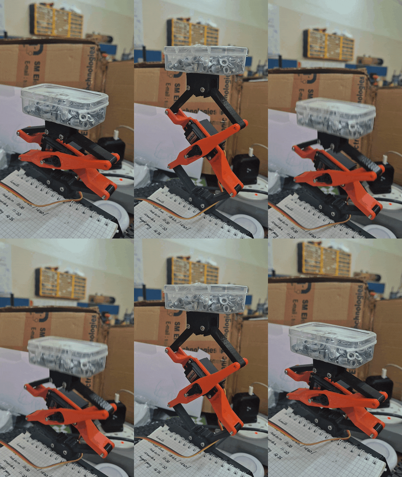
With the platform able to move itself around the floor, all I needed was an actuator that could lift and position the mock charger at different heights. That height adjustment matters because different car models have their charging port at different heights, and the mock charging dock on the car side won't always be identical either.
I found a design that did exactly this at thingiverse.com/thing:5225652 - credit for that goes to SnakeP (thingiverse.com/SnakeP). It worked brilliantly, and mounting it on the Devastator platform was painless.
I was able to lift around 300gms safely. I dare not try more, as I printed in the parts in the default infill of 15% and I do not have the time to reprint it if I broke it just to see how much weight it can lift.
.
The mock charger design
I wanted the charger itself to be forgiving of small positioning errors - remember Part 3 measured up to 3% error on positioning at range. So I leaned into a poka-yoke design (Mistake Proofing) : the charger is made from a length of PVC pipe with a flange on each end. Eventually I'll add a magnet so it sticks to the car once docked. For the robot to actually grab it, I gave the handle two chamfered collars, so the geometry itself nudges the handle into alignment even if the robot's approach isn't perfectly centered.

The grabber design
The grabber is four fingers with a wide opening - essentially a V shape that guides the handle into the locking area, oriented perpendicular to the charging handle itself. Between the chamfered collar and the V fingers, the mechanism forgives about ±1.8cm of positioning error.
I also designed a small dock for the charger to rest in when it's not "charging a car."

here is a video after attaching to the platform. Note that i move the robot ever so slightly to see the grabbing functionality due to positioning errors
Motor calibration, properly this time
An early "it drives straight, good enough" bench calibration turned out not to be good enough once actually measured. Building a proper calibration script - drive the tank in short bursts, watch an Aruco marker mounted on its back with the same fixed camera, measure how far it drifts sideways - surfaced two real problems:
- The two tracks have completely different operating ranges. The right motor doesn't meaningfully engage below roughly duty 170 out of 255 - well past what looked like a normal "slow" setting - while the left motor responds almost linearly from a much lower duty. A calibration sweep that assumed both motors behave similarly at low duty was measuring noise on one side the whole time.
- The true straight-line duty ratio isn't stable. Even once both motors are confirmed moving, the ratio that keeps the tank driving straight drifts measurably over several seconds of sustained driving. The cause was never conclusively identified - thermal effects, battery voltage sag under load, and mechanical wear in the gear train were all plausible, none confirmed.
The calibration script's closed-loop trim search looks like this - drive both tracks at a nominal duty, measure the resulting yaw/drift from the marker, nudge the weaker side:
def find_trim(motor, tracker, base_duty, ...):
    right = base_duty
    for i in range(1, max_iters + 1):
        drift, _ = run_burst(motor, tracker, base_duty, right, burst_s)
        if abs(drift) <= tolerance_frac_s:
            break
        step = trim_sign * kp * drift
        right += max(-20, min(20, step))   # capped per-iteration correction
    return TrimPoint(left_duty=base_duty, right_duty=round(right), ...)
Given point (2) above, chasing a continuous trim curve wasn't worth it - a single calibrated number can't hold indefinitely if the real ratio keeps drifting. The tank instead runs on four fixed duty presets, found by driving, watching, and adjusting by hand rather than trusting the automated search alone:
| Motion | Left duty | Right duty |
|---|---|---|
| Forward | 84 | 178 |
| Backward | -178 | -84 |
| Spin left | -178 | 178 |
| Spin right | 84 | -84 |
Notably asymmetric in both magnitude (right needs much more duty than left to move at all) and direction (which side needs the higher duty flips between forward and backward) - not something a simple "motors are slightly mismatched" model would have predicted, which is exactly why measuring it mattered more than assuming it. The expectation is that a live guidance loop corrects whatever residual drift these fixed presets can't, continuously, rather than a static lookup table being trusted to be right forever.
Vision-guided docking: three wrong designs before a working one
This was the hardest part of the build, and got it wrong three times before it worked.
Wrong design #1: Coding as if the camera moves with the robot. The natural first instinct for "steer toward a target visible in your camera" is to spin until the target is centered in frame - the way you'd drive if the camera were mounted on the robot's own nose. It is not; it's a fixed external camera. Since neither the camera nor a static target ever move regardless of what the robot does, the target's position in the frame carries zero information about which way the robot happens to be facing. The first version of the approach script just span in place, forty steps, learning nothing, because it was optimizing a signal that could never change.
The fix - heading via a probe nudge. With no onboard orientation sensor, heading has to be inferred indirectly: nudge forward briefly, and see how the robot's own tracked marker position shifted as a result. That shift is a real, physical heading vector - and because the nudge is also real forward progress, no motion is wasted purely on sensing:
heading = (rx1 - rx0, rz1 - rz0)          # how the robot's own marker moved
bearing = (goal_x - rx1, goal_z - rz1)    # where the goal is from the new position
angle = signed_angle_deg(*heading, *bearing) * turn_sign
if abs(angle) > heading_tolerance_deg:
    drive_preset("spin_right" if angle > 0 else "spin_left", turn_burst_s)
Wrong design #2: assuming a sign convention carries over. Moving from raw pixel coordinates to real millimeters via solvePnP is more physically meaningful, but it's a different coordinate convention, and the turn_sign that correctly matched pixel-space turned out to be backwards in millimeter-space. One run wasn't caught until the heading/bearing angle grew steadily every single step instead of shrinking, and the tank quietly executed a full U-turn away from the target before it was stopped.
Wrong design #3: "close to the target" isn't "in front of it." solvePnP returns the target marker's own orientation (rvec), not just its position - which means the actual goal is a specific pose: a standoff distance measured along the target's own facing direction, not just a distance radius from a point that could be approached from any angle. The fix projects a goal point using the marker's own facing normal (the third column of its rotation matrix, from cv2.Rodrigues(rvec)), sampled once at startup since the target is assumed static:
r_mat, _ = cv2.Rodrigues(rvec)
nx, nz = r_mat[0, 2], r_mat[2, 2]          # marker's own facing direction, ground-plane
goal_x = target_x + stop_distance_mm * nx
goal_z = target_z + stop_distance_mm * nz
The collisions
Even with all three fixes in place, one run got the robot physically stuck against an obstacle near the target that hadn't been cleared out of the way beforehand. With real motion pinned at zero, the heading-probe signal degenerated into pure measurement noise - a few millimeters of ArUco corner jitter, fed into an angle calculation, can swing the result by well over 100 degrees when the real displacement it's supposed to be measuring is close to zero. The robot spun erratically for dozens of steps on that noise, eventually broke free on a spuriously large heading reading, overshot, and collided with the target.
Two changes came out of that incident:
- Average several quick position samples instead of trusting one frame. A ~150ms polling window, averaged, before any angle math:
def average_position(tracker, marker_id, window_s=0.15, interval_s=0.03): samples = [] deadline = time.monotonic() + window_s while time.monotonic() < deadline: p = tracker.position(marker_id) if p is not None: samples.append(p) time.sleep(interval_s) return sum(s[0] for s in samples) / len(samples), sum(s[1] for s in samples) / len(samples) - Shrink the forward burst duration as the robot nears its goal. Less ground covered per step near the target means a bad correction, if one still slips through, can only carry the robot a small distance rather than a full stride:
if dist >= slowdown_distance_mm: burst_s = probe_burst_s else: burst_s = max(min_burst_s, probe_burst_s * dist / slowdown_distance_mm) - I also re-positioned the camera and re-adjusted the focus so that the target is more sharper. So the error near the target is lower.

Mission orchestration
To make sure Runaways does not happen, I made the movement to a target in phases - Approach, Retreat. In between a manually triggered hand-servo action, Yes i had to keep it manual because I did not want to risk anything breaking, approach a second target the same two-leg way and retreat again → a final close approach directly to the first target's own marker position. Phases run independently rather than as one continuous blocking script, Plus also saves me the the effort of rerunning earlier phases to debug an later phase.
python3 mission.py --phase approach-1        --q-host <ip>   # -> intermediary, then standoff
#   I trigger the servo
python3 mission.py --phase retreat-1         --q-host <ip>   # back up, vision-measured

#   I trigger the servo to the target height (I just eyeball this)
python3 mission.py --phase approach-2        --q-host <ip>   # second target
python3 mission.py --phase retreat-2         --q-host <ip>
python3 mission.py --phase approach-1-final  --q-host <ip>   # close approach, stop-distance=0
Music by MiroMaxMusic from Pixabay
Where it stands, and what's left
Working end-to-end today: camera calibration, multi-marker real-world pose estimation, a fixed motor response, and a vision-guided approach that reliably closes to within centimeters of a target it's never seen before, recovering from its own measurement noise instead of amplifying it.
Still open:
- Orientation, not just position. The approach targets a goal point; nothing yet verifies or corrects the robot's final facing direction once it arrives, which will matter once an actual connector geometry needs to line up rather than just get close. For now I got it working by keeping the initial position only softly titled from final. Any Strong pose difference will never cause proper line up of the gripper and handle. Also Path Planning needs to be there. I have not implemented any expect for an intermediary position target.
- No explicit "I am stuck" detection. A physically blocked robot currently keeps retrying rather than recognizing zero real progress and stopping itself - the collision above happened partly because of this gap.
- No encoders yet. Motors were bought with dual-ended shafts specifically to add magnetic encoders later for real closed-loop speed control, which would likely make a lot of the drift/deadband issues above much smaller problems.
- Automatic Servo Control. This requires me to reprint the hardware with more stronger infills
- End-To-End Automatic Control . This requires time to remove some bugs
Code
All Code to this project can be found here: https://gitlab.com/arvindsa/dockbot-e14-challenge
dockbot-e14-challenge/
├── radxa/            # Vision node (Radxa Q6A): ArUco detection, pose estimation, docking approach
├── arduino-q-linux/  # UNO Q Linux: UDP-in, state machine, serial-out
├── arduino-q-stm32/  # UNO Q, STM32U585 side): bare-metal motor/servo firmware
├── post2/            # Standalone RPi camera server (obsoloete)
├── posts/            # Devlog, one markdown post per entry
radxa/ — vision & positioning
pose_estimation.py,pose_estimation_single_id.py— live ArUco pose viacv2.solvePnP.calibration/— camera calibration capture/fit tooling + fitted.npzfiles.patterns/— printable Arucomarker / calibration-grid generators.motor_calibration/— vision-in-the-loop motor trim tooling (own README).visual_approach.py— drives the tank to a standoff pose relative to one ArUco marker.mission.py— multi-phase mission built onvisual_approach.py(approach → manual servo trigger → retreat → repeat).DEVLOG.md— history, hardware gotchas, and the reasoning behind design choices above.media/— reference photos/video from marker ID and docking sessions.
arduino-q-linux/ — guidance
main.py— entry point; wires UDP receiver, state machine, and serial link together.udp_receiver.py— listens fortarget_posemessages from the Radxa (sender not built yet).guidance.py—DockingController: approach/standoff/touch state machine + steering controller.serial_link.py— sends theM/S/Hcommand protocol to the STM32 over/dev/ttyHS1.web_ui.py— manual bench-test web UI (motor/servo sliders); don't run alongsidemain.py.PROTOCOL.md— both wire formats (Radxa UDP link, STM32 UART link).
arduino-q-stm32/ — real-time firmware
Bare-metal HAL firmware (CubeMX-generated Makefile project, no Arduino sketch layer).
Core/Src/main.c— peripheral init + main loop.Core/Src/motor_control.c— differential-steering tank motor driver (TIM3 PWM).Core/Src/servo_control.c— docking "hand" servo driver (TIM1 PWM).Core/Src/uart_protocol.c— parses theM/S/Hline protocol, enforces command-timeout failsafe.Drivers/— vendor CMSIS + STM32U5xx HAL, unmodified from CubeMX.flash.sh— build + flash over SWD via OpenOCD running on-device
Final Notes
I am submitting this a day late, but I am gonna take up cstanstons offer that Joratcliffe will forgive us. I did not apply for the sponsored kit because I was unsure if i would get time to sit on this project. But as the direction the winds blew changed, I went ahead and made this project. I guess I should have made the final integration outside where there was better light. I strongly feel that most of my positioning errors will go away with better light. Now I have to part ways with the Devastator platform, give it back to my cousin. Farewell. Thank You for charging my cardboard boxes.
If you ask me what would I change if i had to do it all from start? - I'd say, i would have said, something like a small beacon on the charging port of car or a small glowing LED pattern. To communicate that charging is needed or maybe not needed. And Yes, in real life, one can teach an AI model to recognize the pose and location of the actual charging port without the Aruco Marker.
Coincidentally, There are learning resources by e14 - Designing a Mobile Robot Platform with Differential Drive, PID Control and Wireless Mapping. if you need to design robots like this. Until next Challenge.
Do share your comments, and queries.