


1. Introduction
The development of intelligent transportation systems is becoming increasingly important, especially in areas related to healthcare, elderly care, and assistive technologies. Autonomous mobility solutions may one day help people with limited mobility move safely and independently inside hospitals, rehabilitation centers, nursing homes, or smart buildings. Before such systems can be implemented in real-life environments, their control algorithms, safety mechanisms, and sensor systems must first be tested on smaller experimental platforms. The SmartAssist EV project was created with this purpose in mind.
SmartAssist EV is not intended to be a full-sized transport vehicle, but rather an experimental prototype platform designed for testing autonomous navigation, obstacle detection, and smart mobility algorithms. The project is based on a compact DIY DC Smart Robot Car Chassis equipped with magnetic speed encoders. Although small in size, the platform is capable of carrying lightweight objects such as a cup of tea, medicine, or small personal items. This makes it ideal for demonstrating assistive transport concepts in a safe and affordable way.
The vehicle is controlled by the Arduino UNO Q SBC, which acts as the main processing unit of the system. Motor control is handled using the L9110 PWM motor drivers, allowing smooth speed regulation, controlled acceleration, and directional movement of the two DC motors. The magnetic wheel encoders provide feedback about wheel rotation and traveled distance, enabling the platform to follow predefined movement paths with improved precision.
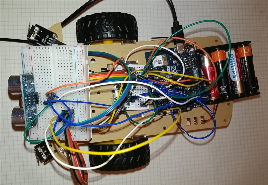
A major focus of the project is safety and environmental awareness. To achieve this, the prototype uses a multi-sensor obstacle detection system based on ultrasonic, infrared (IR) and collision sensors. Each sensing technology provides different advantages and helps improve the reliability of the platform.
Ultrasonic sensors measure the distance to nearby obstacles and help prevent collisions with walls, furniture, or people. Infrared sensors are especially useful for detecting edges, stairs, or low obstacles close to the floor surface.
The data collected from all sensors is processed by the Arduino UNO Q SBC, creating a simple sensor fusion system. This allows the platform to intelligently react to its surroundings by slowing down, stopping, changing direction, or warning the operator when obstacles are detected. The project therefore serves as a practical environment for testing mobility-related safety algorithms and autonomous driving logic.
This project consists of 7 parts. Direct links to the individual articles can be found below:
Part 1 - Experimental Smart Assistive Platform for Elderly and Disabled People
Part 3 - Wireless Command and H-Bridge Direct Drive
Part 4 - Introducing Autonomous Line Following (TCRT5000)
Part 5 - Non-Contact Proactive Shielding (HC-SR04 Range Finder)
Part 6 - Strict Priority Hierarchy with Tactile Mechanical Bumpers
Part 7 - Mobile Robot Control and Live Video Streaming
In this blog, I have provided the most detailed description possible of all the completed stages so that you can build a similar solution yourself.
Main Vehicle Features:
1. Remote Control Operation
The user or caregiver can take full control of the vehicle using a wireless remote controller. This feature increases safety and allows manual obstacle avoidance or route modification whenever needed.
2. Advanced Obstacle Detection System
SmartAssist EV uses a multi-sensor safety system based on ultrasonic, infrared (IR), and collision sensors. By combining multiple sensing technologies, the vehicle can effectively detect obstacles and react in real time.
Ultrasonic sensors are responsible for measuring the distance to obstacles located in front of and beside the vehicle.
Infrared sensors are used to detect:
- edges,
- stairs,
- small obstacles,
- objects located close to the ground.
This solution significantly improves user safety, especially in indoor environments.
The Arduino UNO Q SBC processes data from all sensors simultaneously, creating a basic sensor fusion system. This allows the vehicle to:
- make more accurate decisions,
- reduce false alarms,
- improve driving safety,
- automatically adjust navigation paths.

2. Hardware Platform
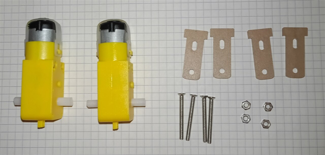
SmartAssist EV (Experimental Smart Assistive Platform for Elderly and Disabled People) is an experimental mobile platform designed to support elderly people and people with disabilities. The system is based on the vehicle platform from the Pico with 32 Modules & Projects: Advanced Kit. However, the Raspberry Pi Pico is not used in the project. Instead, the Arduino UNO Q serves as the main control and computing unit.
Only selected components from the kit are used, primarily the vehicle platform, H-bridges, and sensors. The remaining modules included in the kit are not required for the basic version of the system.
2.1 Mobile Platform
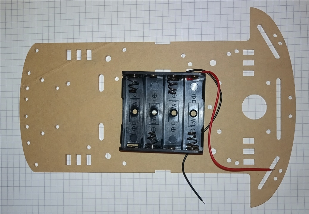
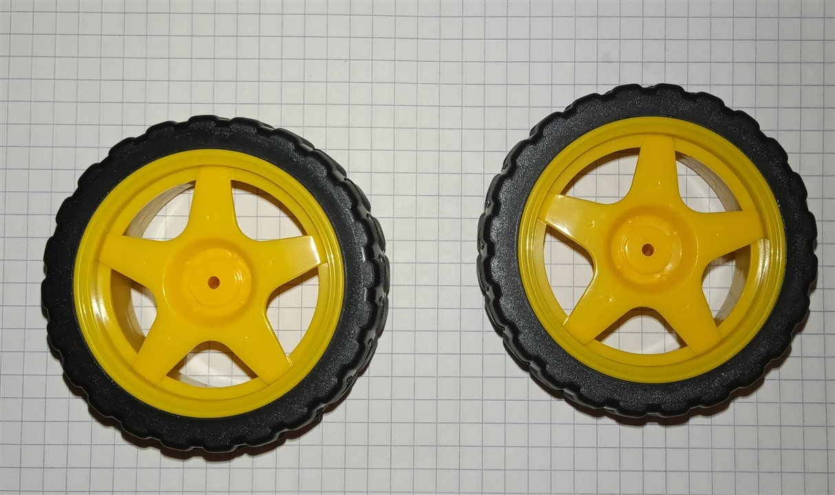
The physical foundation of SmartAssist EV is a small mobile vehicle platform equipped with drive motors and wheels. The platform provides mobility and serves as the mechanical base for the assistive system.
The vehicle can perform basic movements, including:
- moving forward,
- moving backward,
- turning left,
- turning right,
- stopping,
- adjusting the speed of individual motors.
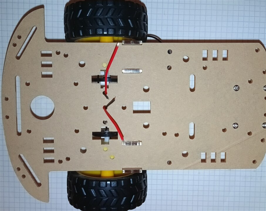
The mobile design allows SmartAssist EV to function not only as a stationary monitoring system but also as a robotic assistive platform capable of responding to its environment.
2.2 Arduino UNO Q
The central component of the system is the Arduino UNO Q. In the original kit, the Raspberry Pi Pico is used as the main controller; however, in SmartAssist EV, the Pico is replaced by the UNO Q.
The Arduino UNO Q is responsible for coordinating the operation of the entire system, including:
- reading data from sensors,
- processing environmental information,
- controlling the vehicle's drive system,
- generating control signals for the H-bridges,
- implementing autonomous operation logic,
- communicating with additional system components,
- implementing experimental intelligent-assistance functions.
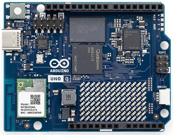
The use of the UNO Q provides a foundation for further development toward more advanced data processing and algorithms supporting autonomous decision-making.
2.3 H-Bridges
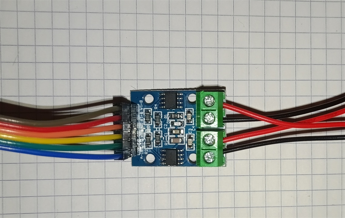
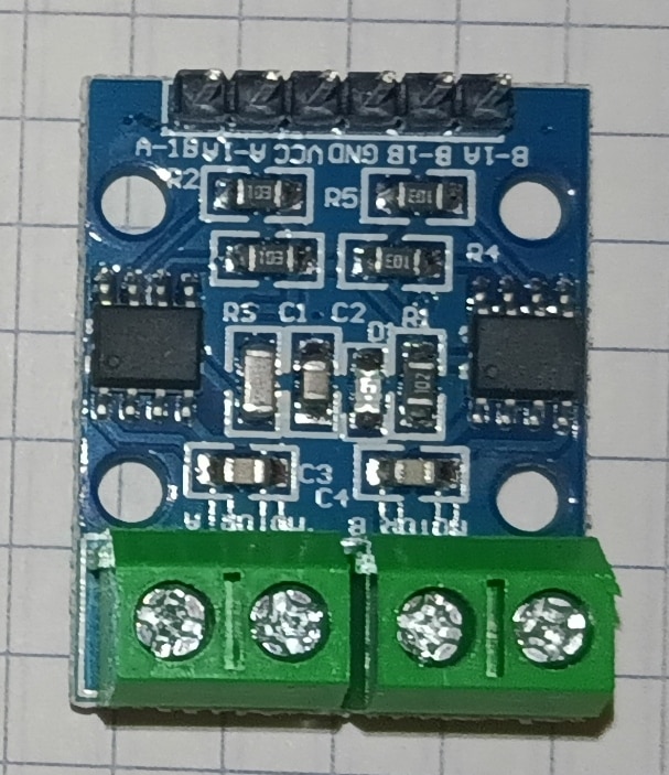
The H-bridges included in the kit are used to control the drive motors. Their purpose is to provide an interface between the Arduino UNO Q and the motors.
The Arduino UNO Q generates the control signals, while the H-bridges provide the appropriate electrical control of the motors. This makes it possible to control the direction of motor rotation and, depending on the particular driver and control method, the motor speed as well.
The basic drive architecture can be represented as:
Arduino UNO Q → H-bridge → motors → vehicle wheels
This approach separates the low-power logic circuitry from the motor power stage and prevents the Arduino board from having to drive the motors directly.
2.4 Sensors
Another important part of SmartAssist EV is the set of sensors used from the kit. Their purpose is to provide the Arduino UNO Q with information about the vehicle's current state and its surrounding environment.
Depending on the particular sensors used, they can provide capabilities such as:
- obstacle detection,
- distance measurement,
- object or presence detection,
- environmental monitoring,
- providing information required for navigation.
The sensor data is processed by the UNO Q and can be used to determine the vehicle's next action.
For example, when an obstacle is detected in front of the vehicle, the system can stop the drive, change its direction, or initiate an obstacle-avoidance procedure.
2.5 Hardware Architecture
The basic hardware architecture of SmartAssist EV consists of three main blocks:
Sensors → Arduino UNO Q → H-bridges → Motors
The Arduino UNO Q is located at the center of the architecture. It receives data from the sensors, interprets the information, and generates appropriate control signals for the drive system.
The system can therefore be divided into two main layers:
- Perception Layer
This layer consists of sensors responsible for observing the vehicle's environment. They provide the input data required for spatial awareness and detection of potential hazards.
- Actuation Layer
This layer consists of the Arduino UNO Q, H-bridges, and motors. Based on information received from the sensors, the system determines the appropriate vehicle behavior and implements it by controlling the motors.
SmartAssist EV is not intended to be a finished medical device, but rather an experimental research and development platform. Its modular architecture allows additional functions to be introduced without fundamentally changing the basic vehicle structure.
The current version focuses on the integration of the mobile vehicle platform, sensors, drive system, and Arduino UNO Q. This configuration provides a foundation for further development of autonomous and assistive functions.
In the future, the platform can be extended with additional sensors, communication systems, user interfaces, audio and visual signaling, and more advanced environmental-analysis mechanisms.
The SmartAssist EV hardware uses only selected components from the Pico with 32 Modules & Projects: Advanced Kit, namely the vehicle platform, drive system, H-bridges, and sensors. The Raspberry Pi Pico is not used in the project; instead, it is replaced by the Arduino UNO Q, which serves as the central controller.
This architecture combines vehicle mobility with environmental sensing and intelligent control, providing a foundation for an experimental assistive system designed to support elderly people and people with disabilities.
3. Wireless Command and H-Bridge Direct Drive
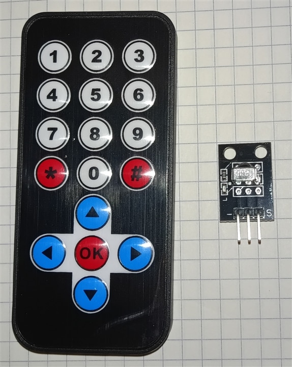
Every robotic vehicle requires a foundation for movement and communication. We begin with an Infrared (IR) receiver based on the standard IRremote library alongside a continuous PWM-controlled H-Bridge system.
By mapping explicit hex codes from a handheld remote, the car acts on standard movement directions. Because a single button press should not trigger indefinite movement, an optional timeout sequence safely cuts power to the motors when the transmitter goes quiet.
This sketch boots the vehicle into manual mode, giving you directional control via your handheld remote. When a key is released, a built-in safety timeout automatically halts the motors to prevent runaway scenarios.
On the Arduino UNO Q board, the analogWrite() function might not work correctly if you explicitly define the pin mode using pinMode(pin, OUTPUT).
Due to its architecture and a known issue in the underlying Zephyr core, removing the pinMode statement from your setup() function allows the PWM signal to generate properly.
How to use analogWrite on UNO Q?
- Do not call pinMode(pin, OUTPUT) for your chosen PWM pin.
- Call analogWrite(pin, value) directly in your code.
- The value ranges from 0 (always off) to 255 (always on).
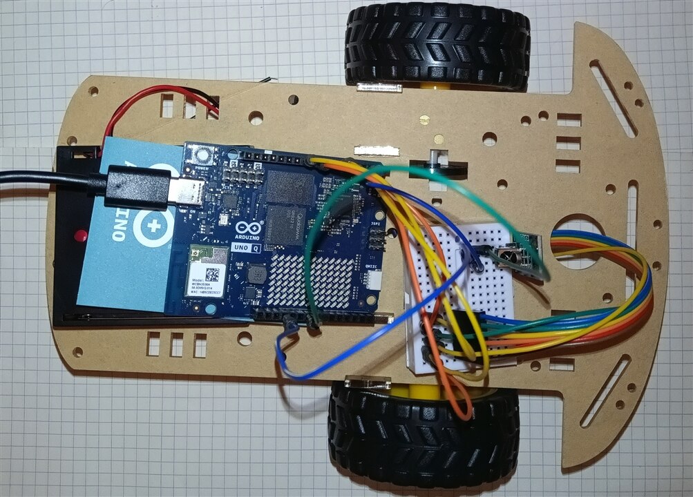
Here is the circuit connection and pin configuration guide for setting up your Arduino board with the L9110S motor driver, IR receiver, and power system.
Pin Mapping Table
| Component | Component Pin | Arduino UNO Q Pin | Notes / Description |
| L9110S Motor Driver | A-1A / A-1B |
Pin 5 (PWM) | Motor A Direction & Speed |
A-1B / A-2A |
Pin 6 (PWM) | Motor A Direction & Speed | |
B-1A / B-1B |
Pin 9 (PWM) | Motor B Direction & Speed | |
B-1B / B-2A |
Pin 10 (PWM) | Motor B Direction & Speed | |
VCC |
External Power (+) | 6V - 12V (Battery pack) | |
GND |
Common Ground (-) | Shared GND with Arduino | |
| IR Receiver | OUT / DATA |
Pin 2 | Signal line (INPUT_PULLUP) |
VCC |
5V / 3.3V | Logic power supply | |
GND |
Common Ground (-) | Shared GND with Arduino |
This Arduino sketch implements a complete control system for a two-wheeled mobile robot managed via an Infrared (IR) remote. It decodes custom IR timing signals, controls DC motors using an L9110S H-bridge driver, provides visual status updates via onboard RGB LEDs, and displays directional arrows on an 8x13 LED matrix.
Key Code Sections
1. Libraries and Hardware Definitions
Imports necessary libraries for the LED matrix and assigns GPIO pins for the L9110S motor driver, IR receiver, and motor speed parameters.
#include <Arduino.h>
#include <Arduino_LED_Matrix.h>   // Library for the 8x13 LED matrix

Arduino_LED_Matrix matrix; // Initialize the large LED matrix

// L9110S Motor Driver Pins on Arduino UNO Q
const int MOTOR_PIN_A1 = 5;
const int MOTOR_PIN_A2 = 6;
const int MOTOR_PIN_B1 = 9;
const int MOTOR_PIN_B2 = 10;

// Infrared Receiver Pin (Configured with PULLUP)
const int IR_RECEIVE_PIN = 2;

// Motor speed (Scale 0-255 for Arduino analogWrite)
const int MOTOR_SPEED = 200;
2. LED Matrix Graphics Arrays
Defines 104-element arrays (8x13 display) storing grayscale values from 0 (OFF) to 7 (max brightness). These pre-rendered graphics represent directional arrows (Up, Down, Left, Right) and an empty frame for stopping.
const uint8_t FRAME_SIZE = 8 * 13; // 104 pixels for the LED matrix

// Example: Arrow Up Array
uint8_t arrow_up[FRAME_SIZE] = {
    0, 0, 0, 0, 0, 0, 7, 0, 0, 0, 0, 0, 0,
    0, 0, 0, 0, 0, 7, 7, 7, 0, 0, 0, 0, 0,
    0, 0, 0, 0, 7, 7, 7, 7, 7, 0, 0, 0, 0,
    0, 0, 0, 7, 7, 0, 7, 0, 7, 7, 0, 0, 0,
    0, 0, 0, 0, 0, 0, 7, 0, 0, 0, 0, 0, 0,
    0, 0, 0, 0, 0, 0, 7, 0, 0, 0, 0, 0, 0,
    0, 0, 0, 0, 0, 0, 7, 0, 0, 0, 0, 0, 0,
    0, 0, 0, 0, 0, 0, 7, 0, 0, 0, 0, 0, 0
};

uint8_t stop_icon[FRAME_SIZE] = { 0 };
3. Onboard RGB LED Helper Functions
Provides utility functions to control status indicator LEDs. set_led3_color uses analog PWM values for smooth color mixing, while set_led4_color handles active-LOW digital switching.
void set_led3_color(int r, int g, int b) {
  analogWrite(LED3_R, r);
  analogWrite(LED3_G, g);
  analogWrite(LED3_B, b);
}

void set_led4_color(bool r, bool g, bool b) {
  digitalWrite(LED4_R, r ? LOW : HIGH);
  digitalWrite(LED4_G, g ? LOW : HIGH);
  digitalWrite(LED4_B, b ? LOW : HIGH);
}
4. Low-Level IR Signal Decoder (readElecrowIR)
Implements custom pulse-width decoding for the Elecrow IR protocol without relying on standard IR libraries. It measures microsecond pulse durations, reconstructs 32 bits (4 bytes) of data, and validates signal integrity using a bitwise checksum (data + data == 0xFF).
long readElecrowIR() {
  int count = 0;

  // 1. Wait for leading LOW pulse
  while (digitalRead(IR_RECEIVE_PIN) == LOW && count < 200) {
    count++;
    delayMicroseconds(60);
  }
  if (count >= 200) return -1;

  // 2. Wait for leading HIGH space
  count = 0;
  while (digitalRead(IR_RECEIVE_PIN) == HIGH && count < 80) {
    count++;
    delayMicroseconds(60);
  }
  if (count >= 80) return -1;

  // 3. Read 32 bits of payload data
  int idx = 0, cnt = 0;
  byte data[4] = {0, 0, 0, 0};

  for (int i = 0; i < 32; i++) {
    count = 0;
    while (digitalRead(IR_RECEIVE_PIN) == LOW && count < 15) {
      count++;
      delayMicroseconds(60);
    }

    count = 0;
    while (digitalRead(IR_RECEIVE_PIN) == HIGH && count < 40) {
      count++;
      delayMicroseconds(60);
    }

    if (count > 8) {
      data[idx] |= (1 << cnt); // Store logical '1'
    }

    if (cnt == 7) { cnt = 0; idx++; } else { cnt++; }
  }

  // 4. Checksum verification
  if ((byte)(data[0] + data[1]) == 0xFF && (byte)(data[2] + data[3]) == 0xFF) {
    return data[2]; // Return valid command byte
  }

  return -1;
}
5. Motor Control and Command Execution
driveMotors sends PWM values directly to the driver pins. executeCommand maps hex command codes (e.g., 0x18 for forward) to corresponding motor movements, LED status colors, and matrix graphics.
void driveMotors(int a1, int a2, int b1, int b2) {
  analogWrite(MOTOR_PIN_A1, a1);
  analogWrite(MOTOR_PIN_A2, a2);
  analogWrite(MOTOR_PIN_B1, b1);
  analogWrite(MOTOR_PIN_B2, b2);
}

void executeCommand(byte command) {
  switch (command) {
    case 0x18: // Up Arrow - Forward
      driveMotors(0, MOTOR_SPEED, 0, MOTOR_SPEED);
      set_led4_color(false, true, false);
      set_led3_color(0, 200, 0);
      matrix.draw(arrow_up);
      break;
    case 0x08: // Left Arrow - Turn Left
      driveMotors(MOTOR_SPEED, 0, 0, MOTOR_SPEED);
      set_led4_color(false, false, true);
      set_led3_color(0, 0, 200);
      matrix.draw(arrow_left);
      break;
    default: // Stop on unassigned keys
      driveMotors(0, 0, 0, 0);
      set_led4_color(false, false, false);
      set_led3_color(0, 0, 0);
      matrix.draw(stop_icon);
      break;
  }
}
6. System Setup and Main Loop (setup & loop)
Configures input pins with internal pull-ups, initializes the display in 3-bit grayscale mode, and continuously polls the IR pin. The loop includes a fail-safe that stops the motors if no active transmission is detected.
void setup() {
  Serial.begin(115200);
  pinMode(IR_RECEIVE_PIN, INPUT_PULLUP); // Enable internal pull-up

  pinMode(LED4_R, OUTPUT);
  pinMode(LED4_G, OUTPUT);
  pinMode(LED4_B, OUTPUT);

  matrix.begin();
  matrix.setGrayscaleBits(3); // Enable 8-level brightness
  matrix.clear();
}

void loop() {
  if (digitalRead(IR_RECEIVE_PIN) == HIGH) {
    long result = readElecrowIR();
    if (result != -1) {
      lastCommand = (byte)result;
    }
  }

  // Safety mechanism: Stop motors if no IR signal is being transmitted
  if (digitalRead(IR_RECEIVE_PIN) == LOW) {
    driveMotors(0, 0, 0, 0);
  } else {
    executeCommand(lastCommand);
  }

  delay(10);
}#include <Arduino.h>
#include <Arduino_LED_Matrix.h> // Library for the 8x13 LED matrix
Arduino_LED_Matrix matrix; // Initialize the large LED matrix
// L9110S Motor Driver Pins on Arduino UNO Q
const int MOTOR_PIN_A1 = 5;
const int MOTOR_PIN_A2 = 6;
const int MOTOR_PIN_B1 = 9;
const int MOTOR_PIN_B2 = 10;
// Infrared Receiver Pin (Configured with PULLUP just like the manufacturer's code)
const int IR_RECEIVE_PIN = 2;
// Motor speed (Scale 0-255 for Arduino analogWrite)
const int MOTOR_SPEED = 200;
// Variable to store the last successfully decoded command
byte lastCommand = 0;
const uint8_t FRAME_SIZE = 8 * 13; // 104 pixels for the LED matrix
// --- LED MATRIX ARROW ARRAYS (Brightness levels 0-7) ---
uint8_t arrow_up[FRAME_SIZE] = {
0, 0, 0, 0, 0, 0, 7, 0, 0, 0, 0, 0, 0,
0, 0, 0, 0, 0, 7, 7, 7, 0, 0, 0, 0, 0,
0, 0, 0, 0, 7, 7, 7, 7, 7, 0, 0, 0, 0,
0, 0, 0, 7, 7, 0, 7, 0, 7, 7, 0, 0, 0,
0, 0, 0, 0, 0, 0, 7, 0, 0, 0, 0, 0, 0,
0, 0, 0, 0, 0, 0, 7, 0, 0, 0, 0, 0, 0,
0, 0, 0, 0, 0, 0, 7, 0, 0, 0, 0, 0, 0,
0, 0, 0, 0, 0, 0, 7, 0, 0, 0, 0, 0, 0
};
uint8_t arrow_down[FRAME_SIZE] = {
0, 0, 0, 0, 0, 0, 7, 0, 0, 0, 0, 0, 0,
0, 0, 0, 0, 0, 0, 7, 0, 0, 0, 0, 0, 0,
0, 0, 0, 0, 0, 0, 7, 0, 0, 0, 0, 0, 0,
0, 0, 0, 0, 0, 0, 7, 0, 0, 0, 0, 0, 0,
0, 0, 0, 7, 7, 0, 7, 0, 7, 7, 0, 0, 0,
0, 0, 0, 0, 7, 7, 7, 7, 7, 0, 0, 0, 0,
0, 0, 0, 0, 0, 7, 7, 7, 0, 0, 0, 0, 0,
0, 0, 0, 0, 0, 0, 7, 0, 0, 0, 0, 0, 0
};
uint8_t arrow_left[FRAME_SIZE] = {
0, 0, 0, 0, 7, 0, 0, 0, 0, 0, 0, 0, 0,
0, 0, 0, 7, 7, 0, 0, 0, 0, 0, 0, 0, 0,
0, 0, 7, 7, 7, 7, 7, 7, 7, 7, 7, 7, 7,
0, 7, 7, 7, 7, 7, 7, 7, 7, 7, 7, 7, 7,
0, 7, 7, 7, 7, 7, 7, 7, 7, 7, 7, 7, 7,
0, 0, 7, 7, 7, 7, 7, 7, 7, 7, 7, 7, 7,
0, 0, 0, 7, 7, 0, 0, 0, 0, 0, 0, 0, 0,
0, 0, 0, 0, 7, 0, 0, 0, 0, 0, 0, 0, 0
};
uint8_t arrow_right[FRAME_SIZE] = {
0, 0, 0, 0, 0, 0, 0, 0, 7, 0, 0, 0, 0,
0, 0, 0, 0, 0, 0, 0, 0, 7, 7, 0, 0, 0,
7, 7, 7, 7, 7, 7, 7, 7, 7, 7, 7, 0, 0,
7, 7, 7, 7, 7, 7, 7, 7, 7, 7, 7, 7, 0,
7, 7, 7, 7, 7, 7, 7, 7, 7, 7, 7, 7, 0,
7, 7, 7, 7, 7, 7, 7, 7, 7, 7, 7, 0, 0,
0, 0, 0, 0, 0, 0, 0, 0, 7, 7, 0, 0, 0,
0, 0, 0, 0, 0, 0, 0, 0, 7, 0, 0, 0, 0
};
uint8_t stop_icon[FRAME_SIZE] = { 0 };
// --- ONBOARD RGB LED CONTROL FUNCTIONS ---
void set_led3_color(int r, int g, int b) {
analogWrite(LED3_R, r);
analogWrite(LED3_G, g);
analogWrite(LED3_B, b);
}
void set_led4_color(bool r, bool g, bool b) {
digitalWrite(LED4_R, r ? LOW : HIGH);
digitalWrite(LED4_G, g ? LOW : HIGH);
digitalWrite(LED4_B, b ? LOW : HIGH);
}
// IR decoding function based exactly on Elecrow's logic and timing
long readElecrowIR() {
int count = 0;
// 1. Wait for the leading LOW pulse
while (digitalRead(IR_RECEIVE_PIN) == LOW && count < 200) {
count++;
delayMicroseconds(60);
}
if (count >= 200) return -1;
// 2. Wait for the leading HIGH space
count = 0;
while (digitalRead(IR_RECEIVE_PIN) == HIGH && count < 80) {
count++;
delayMicroseconds(60);
}
if (count >= 80) return -1;
// 3. Read 32 bits of payload data
int idx = 0;
int cnt = 0;
byte data[4] = {0, 0, 0, 0};
for (int i = 0; i < 32; i++) {
count = 0;
while (digitalRead(IR_RECEIVE_PIN) == LOW && count < 15) {
count++;
delayMicroseconds(60);
}
count = 0;
while (digitalRead(IR_RECEIVE_PIN) == HIGH && count < 40) {
count++;
delayMicroseconds(60);
}
// If the HIGH pulse duration was long (count > 8), register bit as 1
if (count > 8) {
data[idx] |= (1 << cnt);
}
if (cnt == 7) {
cnt = 0;
idx++;
} else {
cnt++;
}
}
// 4. Check checksum integrity (matches Elecrow's condition: data+data==0xFF)
if ((byte)(data[0] + data[1]) == 0xFF && (byte)(data[2] + data[3]) == 0xFF) {
return data[2]; // Returns the valid command byte
}
return -1;
}
void driveMotors(int a1, int a2, int b1, int b2) {
// Omit pinMode() in setup to keep PWM functional on the UNO Q Zephyr core
analogWrite(MOTOR_PIN_A1, a1);
analogWrite(MOTOR_PIN_A2, a2);
analogWrite(MOTOR_PIN_B1, b1);
analogWrite(MOTOR_PIN_B2, b2);
}
void executeCommand(byte command) {
switch (command) {
case 0x18: // Up Arrow - Forward
driveMotors(0, MOTOR_SPEED, 0, MOTOR_SPEED);
set_led4_color(false, true, false);
set_led3_color(0, 200, 0);
matrix.draw(arrow_up);
break;
case 0x08: // Left Arrow - Turn Left
driveMotors(MOTOR_SPEED, 0, 0, MOTOR_SPEED);
set_led4_color(false, false, true);
set_led3_color(0, 0, 200);
matrix.draw(arrow_left);
break;
case 0x5A: // Right Arrow - Turn Right
driveMotors(0, MOTOR_SPEED, MOTOR_SPEED, 0);
set_led4_color(false, false, true);
set_led3_color(0, 0, 200);
matrix.draw(arrow_right);
break;
case 0x52: // Down Arrow - Backward
driveMotors(MOTOR_SPEED, 0, MOTOR_SPEED, 0);
set_led4_color(true, false, false);
set_led3_color(200, 0, 0);
matrix.draw(arrow_down);
break;
default:
driveMotors(0, 0, 0, 0); // Stop for unassigned keys
set_led4_color(false, false, false);
set_led3_color(0, 0, 0);
matrix.draw(stop_icon);
break;
}
}
void setup() {
Serial.begin(115200);
// Enable internal pull-up resistor (Equivalent to Pin.PULL_UP in MicroPython)
pinMode(IR_RECEIVE_PIN, INPUT_PULLUP);
Serial.println("Elecrow IR Decoder for Arduino UNO Q Ready.");
pinMode(LED4_R, OUTPUT); pinMode(LED4_G, OUTPUT); pinMode(LED4_B, OUTPUT);
set_led3_color(0, 0, 0);
set_led4_color(false, false, false);
matrix.begin();
matrix.setGrayscaleBits(3);
matrix.clear();
}
void loop() {
// Main loop logic translated 1:1 from the manufacturer's MicroPython code
if (digitalRead(IR_RECEIVE_PIN) == HIGH) {
long result = readElecrowIR();
if (result != -1) {
lastCommand = (byte)result;
Serial.print("Retrieve key: 0x");
Serial.println(lastCommand, HEX);
}
}
// Safety and control: if the IR pin is HIGH (no transmission), stop the robot.
// Otherwise, continue executing the last received command.
if (digitalRead(IR_RECEIVE_PIN) == LOW) {
driveMotors(0, 0, 0, 0); // Stop
} else {
executeCommand(lastCommand);
}
delay(10); // Small delay for main loop stabilization
}4. Introducing Autonomous Line Following (TCRT5000)
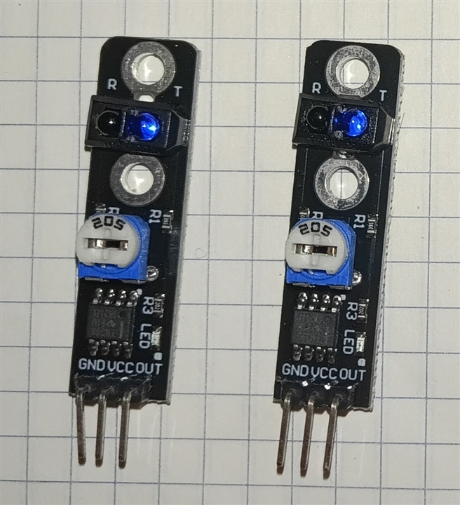
Manual driving is limited by line-of-sight. To implement autonomous navigation, we integrate dual Infrared Line-Tracking Sensors (TrackingPin_L and TrackingPin_R). These sensors output binary feedback depending on whether they detect a highly reflective light floor or a non-reflective dark path.To allow transitioning between manual piloting and automatic tracking, we establish a State Machine using a RobotMode enumeration. Pressing a designated toggle button (0x1C or "OK") alternates the core operating architecture.
This step implements a Finite State Machine utilizing the remote's OK button (0x1C). You can now toggle mid-flight between manual control and an automated tracking routine monitored by the optical sensors on pins A2 and A3.
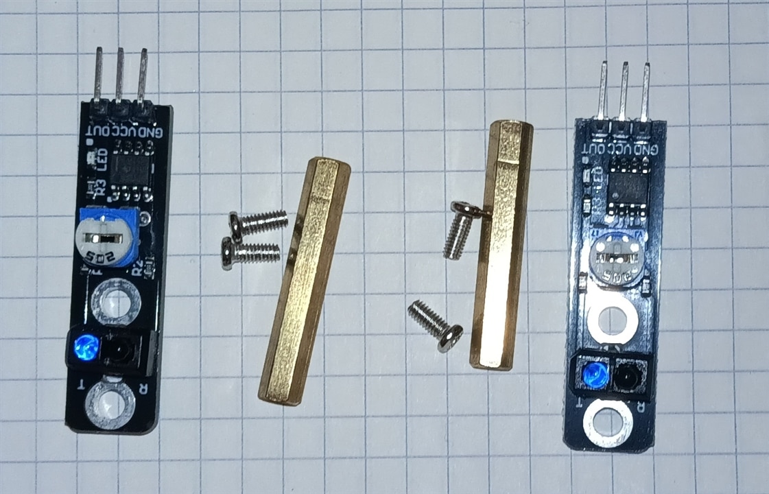
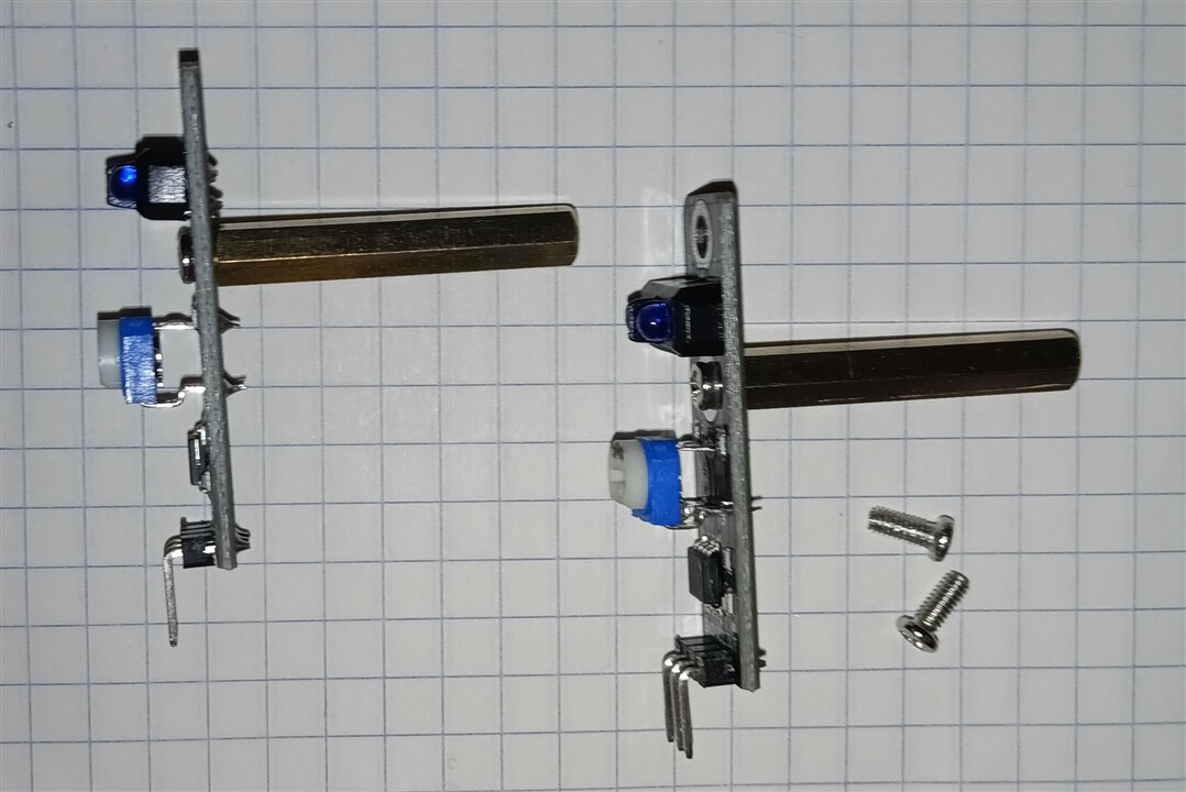
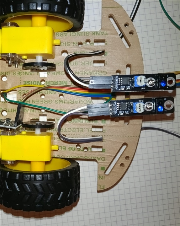
Hardware Wiring Diagram
Each IR tracking sensor module typically uses a 3-pin or 4-pin breakout board:
1. Left Tracking Sensor (TRACKING_PIN_L)
-
VCC Pin: Connects to 5V (or 3.3V, depending on sensor specifications).
-
GND Pin: Connects to GND (Ground).
-
OUT / Signal Pin: Connects to Analog Pin
A2.
2. Right Tracking Sensor (TRACKING_PIN_R)
-
VCC Pin: Connects to 5V (or 3.3V).
-
GND Pin: Connects to GND (Ground).
-
OUT / Signal Pin: Connects to Analog Pin
A3.
Pin Mapping Summary
| Sensor Component | Module Pin | Arduino UNO Q Pin | Wire Function |
| Left Sensor | VCC | 5V | Power supply |
| GND | GND | Common ground | |
| OUT / DO | A2 | Left line detection signal | |
| Right Sensor | VCC | 5V | Power supply |
| GND | GND | Common ground | |
| OUT / DO | A3 | Right line detection signal |
Electrical Notes
-
Internal Pull-Ups: The code configures the pins using
pinMode(A2, INPUT_PULLUP)andpinMode(A3, INPUT_PULLUP). This activates the microcontroller's built-in pull-up resistors, keeping the signal high by default and stabilizing digital state reads (HIGHvsLOW). -
Digital Reading: Although
A2andA3are labeled as analog input pins on the Arduino header, thedigitalRead()function processes them as standard digital binary inputs (returning0or1).
Here is the breakdown of the C code components responsible for line tracking (sensor reading, pin configuration, and autonomous navigation logic).
Line Tracking Code Snippets
1. Sensor Pin Definitions
The line tracking module uses two IR reflectance sensors connected to analog pins A2 (Left) and A3 (Right).
// Infrared Receiver and Tracking Sensor Pins
const int TRACKING_PIN_L = A2; // Left tracking sensor
const int TRACKING_PIN_R = A3; // Right tracking sensor

// Autonomous navigation speed threshold
const int TRACK_SPEED = 160;
2. Pin Configuration in setup()
In setup(), the sensor pins are initialized as inputs with internal pull-up resistors enabled (INPUT_PULLUP) to ensure stable digital reads.
void setup() {
  // Configure line tracking sensor pins as inputs with internal pull-ups
  pinMode(TRACKING_PIN_L, INPUT_PULLUP);
  pinMode(TRACKING_PIN_R, INPUT_PULLUP);
}
3. Operational Mode Toggle (MODE_AUTONOMOUS)
Pressing the OK button (0x1C) on the IR remote toggles between manual IR driving mode and autonomous line-following mode.
case 0x1C: // OK Button on IR Remote
  if (currentMode == MODE_MANUAL) {
    currentMode = MODE_AUTONOMOUS;
    Serial.println("Mode changed: AUTONOMOUS");
  } else {
    currentMode = MODE_MANUAL;
    driveMotors(0, 0, 0, 0); // Stop motors immediately on switch
    Serial.println("Mode changed: MANUAL");
  }
  lastCommand = 0;
  delay(500);
  break;
4. Sensor Reading & Differential Motor Control Loop
Inside loop(), when currentMode == MODE_AUTONOMOUS, the system reads the digital state of both line sensors, combines them into a binary state value (trackState), and adjusts motor outputs accordingly.
else if (currentMode == MODE_AUTONOMOUS) {
  // 1. Read individual sensor pin states (HIGH / LOW)
  int trackL = digitalRead(TRACKING_PIN_L);
  int trackR = digitalRead(TRACKING_PIN_R);

  // 2. Combine signals into a 2-bit state variable (0 to 3)
  // Bit 1 = Left Sensor, Bit 0 = Right Sensor
  int trackState = (trackL * 2) + trackR;

  // 3. Differential steering logic
  switch (trackState) {
    case 0:
      // Both sensors off-line -> Stop
      driveMotors(0, 0, 0, 0);
      break;
    case 1:
      // Right sensor on line -> Turn Right
      driveMotors(0, TRACK_SPEED, TRACK_SPEED, 0);
      break;
    case 2:
      // Left sensor on line -> Turn Left
      driveMotors(TRACK_SPEED, 0, 0, TRACK_SPEED);
      break;
    case 3:
      // Both sensors centered on line -> Drive Forward
      driveMotors(0, TRACK_SPEED, 0, TRACK_SPEED);
      break;
  }
  delay(10); // Short delay to stabilize sensor polling rate
}
Logic Summary
| trackL | trackR | trackState | Action | Description |
0 (LOW) |
0 (LOW) |
0 |
Stop | Line lost or end of track |
0 (LOW) |
1 (HIGH) |
1 |
Turn Right | Vehicle drifted left; right wheel drives forward, left reverses |
1 (HIGH) |
0 (LOW) |
2 |
Turn Left | Vehicle drifted right; left wheel drives forward, right reverses |
1 (HIGH) |
1 (HIGH) |
3 |
Move Forward | Both sensors detect the track; vehicle drives straight ahead |
#include <Arduino.h>
#include <Arduino_LED_Matrix.h> // Library for the 8x13 LED matrix

Arduino_LED_Matrix matrix; // Initialize LED matrix object

// L9110S Motor Driver Pins
const int MOTOR_PIN_A1 = 5;
const int MOTOR_PIN_A2 = 6;
const int MOTOR_PIN_B1 = 9;
const int MOTOR_PIN_B2 = 10;

// Infrared Receiver and Tracking Sensor Pins
const int IR_RECEIVE_PIN = 2;
const int TRACKING_PIN_L = A2;
const int TRACKING_PIN_R = A3;

enum RobotMode {
  MODE_MANUAL,
  MODE_AUTONOMOUS
};

RobotMode currentMode = MODE_MANUAL;

// Speed settings
const int MOTOR_SPEED = 200;
const int TRACK_SPEED = 160;

byte lastCommand = 0;

// LED Matrix Frame Buffer Size (104 pixels)
const uint8_t FRAME_SIZE = 8 * 13;

// --- LED MATRIX ARROW & ICON ARRAYS (Brightness levels 0-7) ---
uint8_t arrow_up[FRAME_SIZE] = {
    0, 0, 0, 0, 0, 0, 7, 0, 0, 0, 0, 0, 0,
    0, 0, 0, 0, 0, 7, 7, 7, 0, 0, 0, 0, 0,
    0, 0, 0, 0, 7, 7, 7, 7, 7, 0, 0, 0, 0,
    0, 0, 0, 7, 7, 0, 7, 0, 7, 7, 0, 0, 0,
    0, 0, 0, 0, 0, 0, 7, 0, 0, 0, 0, 0, 0,
    0, 0, 0, 0, 0, 0, 7, 0, 0, 0, 0, 0, 0,
    0, 0, 0, 0, 0, 0, 7, 0, 0, 0, 0, 0, 0,
    0, 0, 0, 0, 0, 0, 7, 0, 0, 0, 0, 0, 0
};

uint8_t arrow_down[FRAME_SIZE] = {
    0, 0, 0, 0, 0, 0, 7, 0, 0, 0, 0, 0, 0,
    0, 0, 0, 0, 0, 0, 7, 0, 0, 0, 0, 0, 0,
    0, 0, 0, 0, 0, 0, 7, 0, 0, 0, 0, 0, 0,
    0, 0, 0, 0, 0, 0, 7, 0, 0, 0, 0, 0, 0,
    0, 0, 0, 7, 7, 0, 7, 0, 7, 7, 0, 0, 0,
    0, 0, 0, 0, 7, 7, 7, 7, 7, 0, 0, 0, 0,
    0, 0, 0, 0, 0, 7, 7, 7, 0, 0, 0, 0, 0,
    0, 0, 0, 0, 0, 0, 7, 0, 0, 0, 0, 0, 0
};

uint8_t arrow_left[FRAME_SIZE] = {
    0, 0, 0, 0, 7, 0, 0, 0, 0, 0, 0, 0, 0,
    0, 0, 0, 7, 7, 0, 0, 0, 0, 0, 0, 0, 0,
    0, 0, 7, 7, 7, 7, 7, 7, 7, 7, 7, 7, 7,
    0, 7, 7, 7, 7, 7, 7, 7, 7, 7, 7, 7, 7,
    0, 7, 7, 7, 7, 7, 7, 7, 7, 7, 7, 7, 7,
    0, 0, 7, 7, 7, 7, 7, 7, 7, 7, 7, 7, 7,
    0, 0, 0, 7, 7, 0, 0, 0, 0, 0, 0, 0, 0,
    0, 0, 0, 0, 7, 0, 0, 0, 0, 0, 0, 0, 0
};

uint8_t arrow_right[FRAME_SIZE] = {
    0, 0, 0, 0, 0, 0, 0, 0, 7, 0, 0, 0, 0,
    0, 0, 0, 0, 0, 0, 0, 0, 7, 7, 0, 0, 0,
    7, 7, 7, 7, 7, 7, 7, 7, 7, 7, 7, 0, 0,
    7, 7, 7, 7, 7, 7, 7, 7, 7, 7, 7, 7, 0,
    7, 7, 7, 7, 7, 7, 7, 7, 7, 7, 7, 7, 0,
    7, 7, 7, 7, 7, 7, 7, 7, 7, 7, 7, 0, 0,
    0, 0, 0, 0, 0, 0, 0, 0, 7, 7, 0, 0, 0,
    0, 0, 0, 0, 0, 0, 0, 0, 7, 0, 0, 0, 0
};

uint8_t stop_icon[FRAME_SIZE] = { 0 };

// Autonomous Mode Icon (Letter "A")
uint8_t auto_icon[FRAME_SIZE] = {
    0, 0, 0, 0, 0, 7, 7, 7, 0, 0, 0, 0, 0,
    0, 0, 0, 0, 7, 0, 0, 0, 7, 0, 0, 0, 0,
    0, 0, 0, 0, 7, 0, 0, 0, 7, 0, 0, 0, 0,
    0, 0, 0, 0, 7, 7, 7, 7, 7, 0, 0, 0, 0,
    0, 0, 0, 0, 7, 0, 0, 0, 7, 0, 0, 0, 0,
    0, 0, 0, 0, 7, 0, 0, 0, 7, 0, 0, 0, 0,
    0, 0, 0, 0, 7, 0, 0, 0, 7, 0, 0, 0, 0,
    0, 0, 0, 0, 0, 0, 0, 0, 0, 0, 0, 0, 0
};

// --- ONBOARD RGB LED FUNCTIONS ---
void set_led3_color(int r, int g, int b) {
  analogWrite(LED3_R, r);
  analogWrite(LED3_G, g);
  analogWrite(LED3_B, b);
}

void set_led4_color(bool r, bool g, bool b) {
  digitalWrite(LED4_R, r ? LOW : HIGH);
  digitalWrite(LED4_G, g ? LOW : HIGH);
  digitalWrite(LED4_B, b ? LOW : HIGH);
}

// Elecrow IR Decoder
long readElecrowIR() {
  int count = 0;
  while (digitalRead(IR_RECEIVE_PIN) == LOW && count < 200) { count++; delayMicroseconds(60); }
  if (count >= 200) return -1;

  count = 0;
  while (digitalRead(IR_RECEIVE_PIN) == HIGH && count < 80) { count++; delayMicroseconds(60); }
  if (count >= 80) return -1;

  int idx = 0, cnt = 0;
  byte data[4] = {0, 0, 0, 0};

  for (int i = 0; i < 32; i++) {
    count = 0;
    while (digitalRead(IR_RECEIVE_PIN) == LOW && count < 15) { count++; delayMicroseconds(60); }
    count = 0;
    while (digitalRead(IR_RECEIVE_PIN) == HIGH && count < 40) { count++; delayMicroseconds(60); }

    if (count > 8) data[idx] |= (1 << cnt);

    if (cnt == 7) { cnt = 0; idx++; } else { cnt++; }
  }

  if ((byte)(data[0] + data[1]) == 0xFF && (byte)(data[2] + data[3]) == 0xFF) {
    return data[2];
  }
  return -1;
}

void driveMotors(int a1, int a2, int b1, int b2) {
  analogWrite(MOTOR_PIN_A1, a1);
  analogWrite(MOTOR_PIN_A2, a2);
  analogWrite(MOTOR_PIN_B1, b1);
  analogWrite(MOTOR_PIN_B2, b2);
}

void executeCommand(byte command) {
  switch (command) {
    case 0x1C: // OK Button - Toggle Operational Mode
      if (currentMode == MODE_MANUAL) {
        currentMode = MODE_AUTONOMOUS;
        Serial.println("Mode changed: AUTONOMOUS");
      } else {
        currentMode = MODE_MANUAL;
        driveMotors(0, 0, 0, 0);
        Serial.println("Mode changed: MANUAL");
      }
      lastCommand = 0;
      delay(500);
      break;

    case 0x18: // Forward
      if (currentMode == MODE_MANUAL) {
        driveMotors(0, MOTOR_SPEED, 0, MOTOR_SPEED);
        set_led4_color(false, true, false); // Green
        set_led3_color(0, 200, 0);
        matrix.draw(arrow_up);
      }
      break;

    case 0x08: // Turn Left
      if (currentMode == MODE_MANUAL) {
        driveMotors(MOTOR_SPEED, 0, 0, MOTOR_SPEED);
        set_led4_color(false, false, true); // Blue
        set_led3_color(0, 0, 200);
        matrix.draw(arrow_left);
      }
      break;

    case 0x5A: // Turn Right
      if (currentMode == MODE_MANUAL) {
        driveMotors(0, MOTOR_SPEED, MOTOR_SPEED, 0);
        set_led4_color(false, false, true); // Blue
        set_led3_color(0, 0, 200);
        matrix.draw(arrow_right);
      }
      break;

    case 0x52: // Backward
      if (currentMode == MODE_MANUAL) {
        driveMotors(MOTOR_SPEED, 0, MOTOR_SPEED, 0);
        set_led4_color(true, false, false); // Red
        set_led3_color(200, 0, 0);
        matrix.draw(arrow_down);
      }
      break;

    default:
      if (currentMode == MODE_MANUAL) {
        driveMotors(0, 0, 0, 0);
        set_led4_color(false, false, false);
        set_led3_color(0, 0, 0);
        matrix.draw(stop_icon);
      }
      break;
  }
}

void setup() {
  Serial.begin(115200);

  pinMode(IR_RECEIVE_PIN, INPUT_PULLUP);
  pinMode(TRACKING_PIN_L, INPUT_PULLUP);
  pinMode(TRACKING_PIN_R, INPUT_PULLUP);

  // RGB LED Pin Configuration
  pinMode(LED4_R, OUTPUT); pinMode(LED4_G, OUTPUT); pinMode(LED4_B, OUTPUT);
  set_led3_color(0, 0, 0);
  set_led4_color(false, false, false);

  // Initialize LED Matrix
  matrix.begin();
  matrix.setGrayscaleBits(3); // 8 brightness levels (0-7)
  matrix.clear();

  Serial.println("Robot Ready with LED Matrix and RGB Feedback.");
}

void loop() {
  // 1. Read IR Signal
  if (digitalRead(IR_RECEIVE_PIN) == LOW) {
    long result = readElecrowIR();
    if (result != -1) {
      lastCommand = (byte)result;
      executeCommand(lastCommand);
    }
  }

  // 2. Mode Execution Loop
  if (currentMode == MODE_MANUAL) {
    if (digitalRead(IR_RECEIVE_PIN) == HIGH) {
      driveMotors(0, 0, 0, 0);
      set_led4_color(false, false, false);
      set_led3_color(0, 0, 0);
      matrix.draw(stop_icon);
    } else {
      executeCommand(lastCommand);
    }
  }
  else if (currentMode == MODE_AUTONOMOUS) {
    // Show Autonomous icon ("A") and set indicator LEDs to Yellow/Cyan
    matrix.draw(auto_icon);
    set_led4_color(true, true, false);
    set_led3_color(100, 100, 0);

    int trackL = digitalRead(TRACKING_PIN_L);
    int trackR = digitalRead(TRACKING_PIN_R);
    int trackState = (trackL * 2) + trackR;

    switch (trackState) {
      case 0: driveMotors(0, 0, 0, 0); break;                           // Stop
      case 1: driveMotors(0, TRACK_SPEED, TRACK_SPEED, 0); break;       // Turn Right
      case 2: driveMotors(TRACK_SPEED, 0, 0, TRACK_SPEED); break;       // Turn Left
      case 3: driveMotors(0, TRACK_SPEED, 0, TRACK_SPEED); break;       // Move Forward
    }
    delay(10);
  }
}
5.Non-Contact Proactive Shielding (HC-SR04 Range Finder)
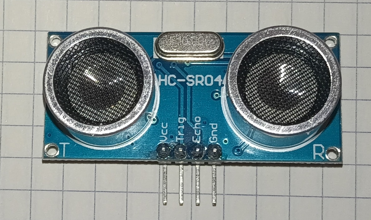
An autonomous tracking system can easily collide with static roadblocks. To mitigate this risk, we add an Ultrasonic Distance Module (HC-SR04). This sensor proactively measures the distance to upcoming obstacles by calculating the time-of-flight of high-frequency audio pings.To prevent software lag, we supply a 30,000 microsecond hardware limit to the pulseIn() function. This prevents the script from freezing if the sensor misses an echo pulse. If the calculated clearance falls beneath 30 cm, the robot suspends line tracking and maneuvers away.
Here, the vehicle gains a contact-free defensive boundary. While navigating autonomously, if the ultrasonic sonar module captures a barrier closing within 30 cm, the robot overrides line following to execute a sharp evasive turn away from danger.
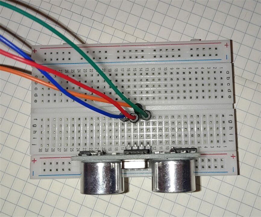
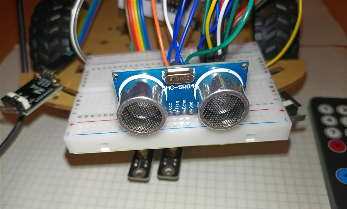
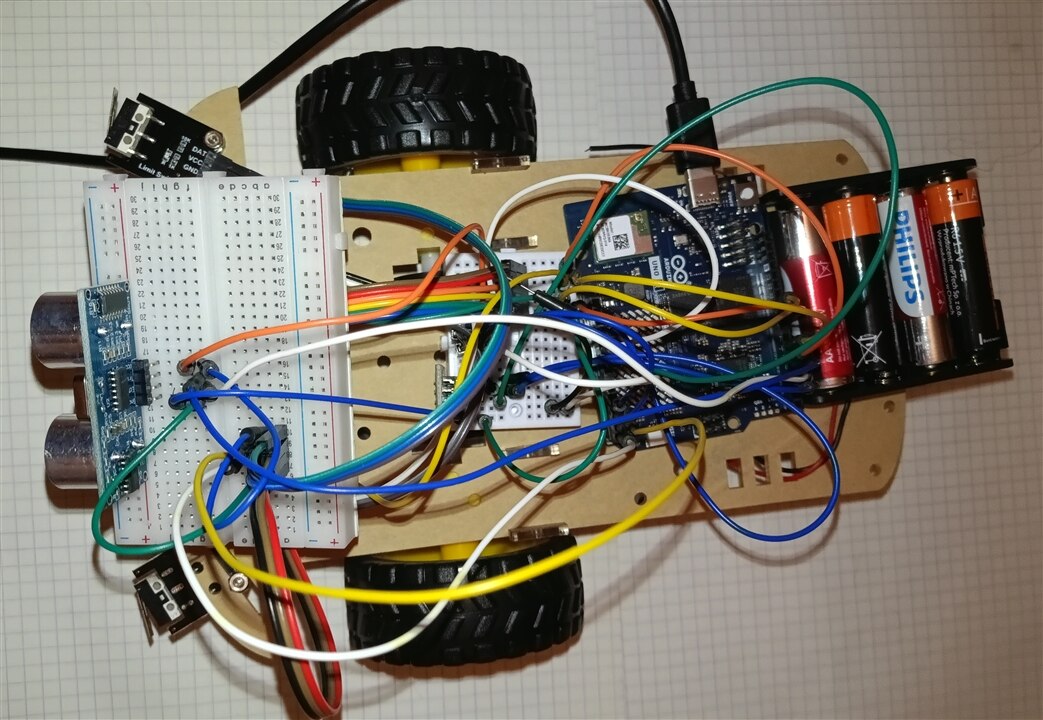
Essential Code Snippets Related to the Ultrasonic Sensor
1. Hardware Pin Definitions
Pin assignments for the HC-SR04 sonar module:
// Ultrasonic HC-SR04 Sonar Pins
const int TRIG_PIN = 4;
const int ECHO_PIN = 3;
2. Pin Setup in setup()
Configures TRIG_PIN to output pulses and ECHO_PIN to listen for returning sound waves:
// Ultrasonic Sonar pins configuration
pinMode(TRIG_PIN, OUTPUT);
pinMode(ECHO_PIN, INPUT);
3. Distance Measurement Routine (getDistance())
Generates a 10us ultrasonic burst and measures echo response time to calculate distance in centimeters. Includes a 30 ms hardware timeout to prevent code execution freezes:
float getDistance() {
  digitalWrite(TRIG_PIN, LOW);
  delayMicroseconds(2);
  digitalWrite(TRIG_PIN, HIGH);
  delayMicroseconds(10);
  digitalWrite(TRIG_PIN, LOW);

  // 30ms hardware timeout constraint to avoid freezing the main execution loop
  long duration = pulseIn(ECHO_PIN, HIGH, 30000);
  float d = duration * 0.0343 / 2;

  if (d == 0) return 999.0; // Return out-of-bounds constant on reading error
  return d;
}
4. Obstacle Avoidance Logic in loop()
When operating in MODE_AUTONOMOUS, distance is checked before line tracking logic. If an obstacle is detected closer than 30 cm line tracking is temporarily overridden, and the robot performs an evasive left turn:
else if (currentMode == MODE_AUTONOMOUS) {
  float distance = getDistance();

  // Obstacle avoidance matching Elecrow's motor logic and 0.3s timing
  if (distance < 30.0) {
    Serial.println("Obstacle detected! Turning left...");
    driveMotors(MOTOR_SPEED, 0, 0, MOTOR_SPEED); // Spin Left in place
    delay(300);                                  // Turn duration
  }
  else {
    // Standard Line Tracking routine executes here...
  }
}
#include <Arduino.h>
#include <Arduino_LED_Matrix.h> // Library for the 8x13 LED matrix

Arduino_LED_Matrix matrix; // Initialize LED matrix object

// L9110S Motor Driver Pins
const int MOTOR_PIN_A1 = 5;
const int MOTOR_PIN_A2 = 6;
const int MOTOR_PIN_B1 = 9;
const int MOTOR_PIN_B2 = 10;

// Infrared Receiver Pin
const int IR_RECEIVE_PIN = 2;

// Line Tracking Sensor Pins
const int TRACKING_PIN_L = A2;
const int TRACKING_PIN_R = A3;

// Ultrasonic HC-SR04 Sonar Pins
const int TRIG_PIN = 4;
const int ECHO_PIN = 3;

enum RobotMode {
  MODE_MANUAL,
  MODE_AUTONOMOUS
};

RobotMode currentMode = MODE_MANUAL;

// Speed settings
const int MOTOR_SPEED = 200;
const int TRACK_SPEED = 160;

byte lastCommand = 0;

// LED Matrix Frame Buffer Size (104 pixels)
const uint8_t FRAME_SIZE = 8 * 13;

// --- LED MATRIX ARROW & ICON ARRAYS (Brightness levels 0-7) ---
uint8_t arrow_up[FRAME_SIZE] = {
    0, 0, 0, 0, 0, 0, 7, 0, 0, 0, 0, 0, 0,
    0, 0, 0, 0, 0, 7, 7, 7, 0, 0, 0, 0, 0,
    0, 0, 0, 0, 7, 7, 7, 7, 7, 0, 0, 0, 0,
    0, 0, 0, 7, 7, 0, 7, 0, 7, 7, 0, 0, 0,
    0, 0, 0, 0, 0, 0, 7, 0, 0, 0, 0, 0, 0,
    0, 0, 0, 0, 0, 0, 7, 0, 0, 0, 0, 0, 0,
    0, 0, 0, 0, 0, 0, 7, 0, 0, 0, 0, 0, 0,
    0, 0, 0, 0, 0, 0, 7, 0, 0, 0, 0, 0, 0
};

uint8_t arrow_down[FRAME_SIZE] = {
    0, 0, 0, 0, 0, 0, 7, 0, 0, 0, 0, 0, 0,
    0, 0, 0, 0, 0, 0, 7, 0, 0, 0, 0, 0, 0,
    0, 0, 0, 0, 0, 0, 7, 0, 0, 0, 0, 0, 0,
    0, 0, 0, 0, 0, 0, 7, 0, 0, 0, 0, 0, 0,
    0, 0, 0, 7, 7, 0, 7, 0, 7, 7, 0, 0, 0,
    0, 0, 0, 0, 7, 7, 7, 7, 7, 0, 0, 0, 0,
    0, 0, 0, 0, 0, 7, 7, 7, 0, 0, 0, 0, 0,
    0, 0, 0, 0, 0, 0, 7, 0, 0, 0, 0, 0, 0
};

uint8_t arrow_left[FRAME_SIZE] = {
    0, 0, 0, 0, 7, 0, 0, 0, 0, 0, 0, 0, 0,
    0, 0, 0, 7, 7, 0, 0, 0, 0, 0, 0, 0, 0,
    0, 0, 7, 7, 7, 7, 7, 7, 7, 7, 7, 7, 7,
    0, 7, 7, 7, 7, 7, 7, 7, 7, 7, 7, 7, 7,
    0, 7, 7, 7, 7, 7, 7, 7, 7, 7, 7, 7, 7,
    0, 0, 7, 7, 7, 7, 7, 7, 7, 7, 7, 7, 7,
    0, 0, 0, 7, 7, 0, 0, 0, 0, 0, 0, 0, 0,
    0, 0, 0, 0, 7, 0, 0, 0, 0, 0, 0, 0, 0
};

uint8_t arrow_right[FRAME_SIZE] = {
    0, 0, 0, 0, 0, 0, 0, 0, 7, 0, 0, 0, 0,
    0, 0, 0, 0, 0, 0, 0, 0, 7, 7, 0, 0, 0,
    7, 7, 7, 7, 7, 7, 7, 7, 7, 7, 7, 0, 0,
    7, 7, 7, 7, 7, 7, 7, 7, 7, 7, 7, 7, 0,
    7, 7, 7, 7, 7, 7, 7, 7, 7, 7, 7, 7, 0,
    7, 7, 7, 7, 7, 7, 7, 7, 7, 7, 7, 0, 0,
    0, 0, 0, 0, 0, 0, 0, 0, 7, 7, 0, 0, 0,
    0, 0, 0, 0, 0, 0, 0, 0, 7, 0, 0, 0, 0
};

uint8_t stop_icon[FRAME_SIZE] = { 0 };

// --- ONBOARD RGB LED FUNCTIONS ---
void set_led3_color(int r, int g, int b) {
  analogWrite(LED3_R, r);
  analogWrite(LED3_G, g);
  analogWrite(LED3_B, b);
}

void set_led4_color(bool r, bool g, bool b) {
  digitalWrite(LED4_R, r ? LOW : HIGH);
  digitalWrite(LED4_G, g ? LOW : HIGH);
  digitalWrite(LED4_B, b ? LOW : HIGH);
}

// Elecrow IR Decoder
long readElecrowIR() {
  int count = 0;
  while (digitalRead(IR_RECEIVE_PIN) == LOW && count < 200) { count++; delayMicroseconds(60); }
  if (count >= 200) return -1;

  count = 0;
  while (digitalRead(IR_RECEIVE_PIN) == HIGH && count < 80) { count++; delayMicroseconds(60); }
  if (count >= 80) return -1;

  int idx = 0, cnt = 0;
  byte data[4] = {0, 0, 0, 0};

  for (int i = 0; i < 32; i++) {
    count = 0;
    while (digitalRead(IR_RECEIVE_PIN) == LOW && count < 15) { count++; delayMicroseconds(60); }
    count = 0;
    while (digitalRead(IR_RECEIVE_PIN) == HIGH && count < 40) { count++; delayMicroseconds(60); }

    if (count > 8) data[idx] |= (1 << cnt);

    if (cnt == 7) { cnt = 0; idx++; } else { cnt++; }
  }

  if ((byte)(data[0] + data[1]) == 0xFF && (byte)(data[2] + data[3]) == 0xFF) {
    return data[2];
  }
  return -1;
}

void driveMotors(int a1, int a2, int b1, int b2) {
  analogWrite(MOTOR_PIN_A1, a1);
  analogWrite(MOTOR_PIN_A2, a2);
  analogWrite(MOTOR_PIN_B1, b1);
  analogWrite(MOTOR_PIN_B2, b2);
}

float getDistance() {
  digitalWrite(TRIG_PIN, LOW);
  delayMicroseconds(2);
  digitalWrite(TRIG_PIN, HIGH);
  delayMicroseconds(10);
  digitalWrite(TRIG_PIN, LOW);

  long duration = pulseIn(ECHO_PIN, HIGH, 30000);
  float d = duration * 0.0343 / 2;

  if (d == 0) return 999.0;
  return d;
}

void executeCommand(byte command) {
  switch (command) {
    case 0x1C: // OK Button - Toggle Manual / Autonomous Operations
      if (currentMode == MODE_MANUAL) {
        currentMode = MODE_AUTONOMOUS;
        Serial.println("Mode changed: AUTONOMOUS (Tracking + Sonar)");
      }
      else {
        currentMode = MODE_MANUAL;
        driveMotors(0, 0, 0, 0);
        set_led4_color(false, false, false);
        set_led3_color(0, 0, 0);
        matrix.draw(stop_icon);
        Serial.println("Mode changed: MANUAL (IR Control)");
      }
      lastCommand = 0;
      delay(500);
      break;

    case 0x18: // Forward
      if (currentMode == MODE_MANUAL) {
        driveMotors(0, MOTOR_SPEED, 0, MOTOR_SPEED);
        set_led4_color(false, true, false); // Green
        set_led3_color(0, 200, 0);
        matrix.draw(arrow_up);
      }
      break;

    case 0x08: // Spin Left
      if (currentMode == MODE_MANUAL) {
        driveMotors(MOTOR_SPEED, 0, 0, MOTOR_SPEED);
        set_led4_color(false, false, true); // Blue
        set_led3_color(0, 0, 200);
        matrix.draw(arrow_left);
      }
      break;

    case 0x5A: // Spin Right
      if (currentMode == MODE_MANUAL) {
        driveMotors(0, MOTOR_SPEED, MOTOR_SPEED, 0);
        set_led4_color(false, false, true); // Blue
        set_led3_color(0, 0, 200);
        matrix.draw(arrow_right);
      }
      break;

    case 0x52: // Backward
      if (currentMode == MODE_MANUAL) {
        driveMotors(MOTOR_SPEED, 0, MOTOR_SPEED, 0);
        set_led4_color(true, false, false); // Red
        set_led3_color(200, 0, 0);
        matrix.draw(arrow_down);
      }
      break;

    default:
      if (currentMode == MODE_MANUAL) {
        driveMotors(0, 0, 0, 0);
        set_led4_color(false, false, false);
        set_led3_color(0, 0, 0);
        matrix.draw(stop_icon);
      }
      break;
  }
}

void setup() {
  Serial.begin(115200);

  pinMode(IR_RECEIVE_PIN, INPUT_PULLUP);
  pinMode(TRACKING_PIN_L, INPUT_PULLUP);
  pinMode(TRACKING_PIN_R, INPUT_PULLUP);

  pinMode(TRIG_PIN, OUTPUT);
  pinMode(ECHO_PIN, INPUT);

  // RGB LED Pin Configuration
  pinMode(LED4_R, OUTPUT);
  pinMode(LED4_G, OUTPUT);
  pinMode(LED4_B, OUTPUT);
  set_led3_color(0, 0, 0);
  set_led4_color(false, false, false);

  // Initialize LED Matrix
  matrix.begin();
  matrix.setGrayscaleBits(3); // 8 brightness levels (0-7)
  matrix.clear();

  Serial.println("System Ready on Arduino UNO Q (IR + Line Tracking + Sonar + Matrix/LEDs).");
}

void loop() {
  // 1. Process incoming IR signals
  if (digitalRead(IR_RECEIVE_PIN) == LOW) {
    long result = readElecrowIR();
    if (result != -1) {
      lastCommand = (byte)result;
      executeCommand(lastCommand);
    }
  }

  // 2. Continuous Mode Execution
  if (currentMode == MODE_MANUAL) {
    if (digitalRead(IR_RECEIVE_PIN) == HIGH) {
      driveMotors(0, 0, 0, 0);
      set_led4_color(false, false, false);
      set_led3_color(0, 0, 0);
      matrix.draw(stop_icon);
    } else {
      executeCommand(lastCommand);
    }
  }
  else if (currentMode == MODE_AUTONOMOUS) {
    float distance = getDistance();

    // Priority 1: Ultrasonic Obstacle Avoidance
    if (distance < 30.0) {
      Serial.println("Obstacle detected! Evading left...");
      driveMotors(MOTOR_SPEED, 0, 0, MOTOR_SPEED); // Spin Left in place
      set_led4_color(true, false, false);          // Red warning
      set_led3_color(200, 0, 0);
      matrix.draw(arrow_left);                     // Indicate left evasion turn
      delay(300);                                  // Turn duration
    }
    // Priority 2: Line Tracking Routine
    else {
      int trackL = digitalRead(TRACKING_PIN_L);
      int trackR = digitalRead(TRACKING_PIN_R);
      int trackState = (trackL * 2) + trackR;

      switch (trackState) {
        case 0: // Off track -> Stop
          driveMotors(0, 0, 0, 0);
          set_led4_color(false, false, false);
          set_led3_color(0, 0, 0);
          matrix.draw(stop_icon);
          break;

        case 1: // Right sensor active -> Turn Right
          driveMotors(0, TRACK_SPEED, TRACK_SPEED, 0);
          set_led4_color(false, false, true); // Blue
          set_led3_color(0, 0, 200);
          matrix.draw(arrow_right);
          break;

        case 2: // Left sensor active -> Turn Left
          driveMotors(TRACK_SPEED, 0, 0, TRACK_SPEED);
          set_led4_color(false, false, true); // Blue
          set_led3_color(0, 0, 200);
          matrix.draw(arrow_left);
          break;

        case 3: // Both sensors active -> Move Forward
          driveMotors(0, TRACK_SPEED, 0, TRACK_SPEED);
          set_led4_color(false, true, false); // Green
          set_led3_color(0, 200, 0);
          matrix.draw(arrow_up);
          break;
      }
      delay(10);
    }
  }
}
6. Strict Priority Hierarchy with Tactile Mechanical Bumpers
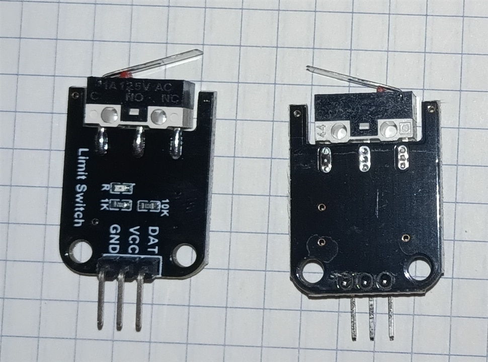
Ultrasonic sensors can miss low-profile objects, clear glass, or acoustic-absorbing fabrics. To handle these blind spots, we add physical Tactile Bumper Switches (CollisionPin_L, CollisionPin_R) as a final layer of defense.To manage all these inputs, the code uses a Strict Priority Hierarchy inside the core runtime evaluation loop:Priority 1 (Highest): Tactile Impact Check. If a physical collision is registered, the robot stops everything, backs up, and executes a wide turning maneuver.Priority 2 (Medium): Ultrasonic Proactive Clearance. If an object is detected within 30cm, the robot performs a quick corrective turn to avoid an accident.Priority 3 (Lowest): Standard Path Following. If both safety systems report a clear path, the robot continues tracking the line.
The full software build adds tactical mechanical bumper microswitches routed to pins A4 (18) and A5 (19). This program runs a rigorous hierarchy matrix: physical bumper triggers grab immediate absolute priority (initiating multi-second reversing maneuvers), sonar triggers handle medium-priority non-contact adjustments, while line following proceeds only when both safety nets report a clear path.
Here is the final, production-ready source architecture merging all four functional modules:
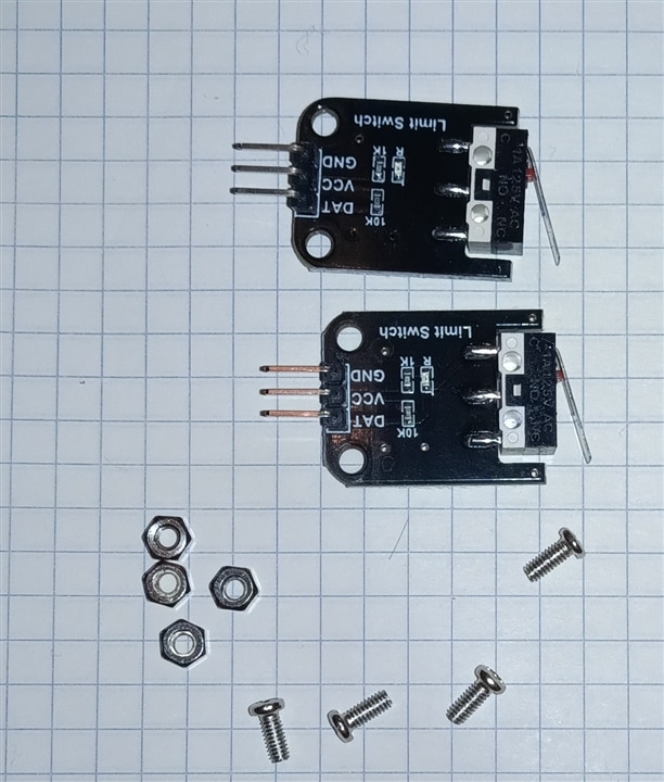
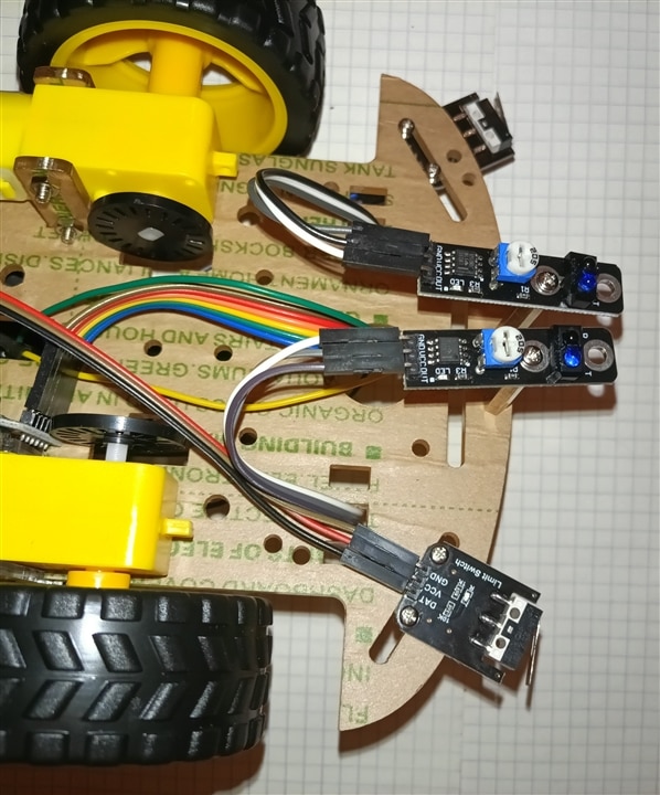
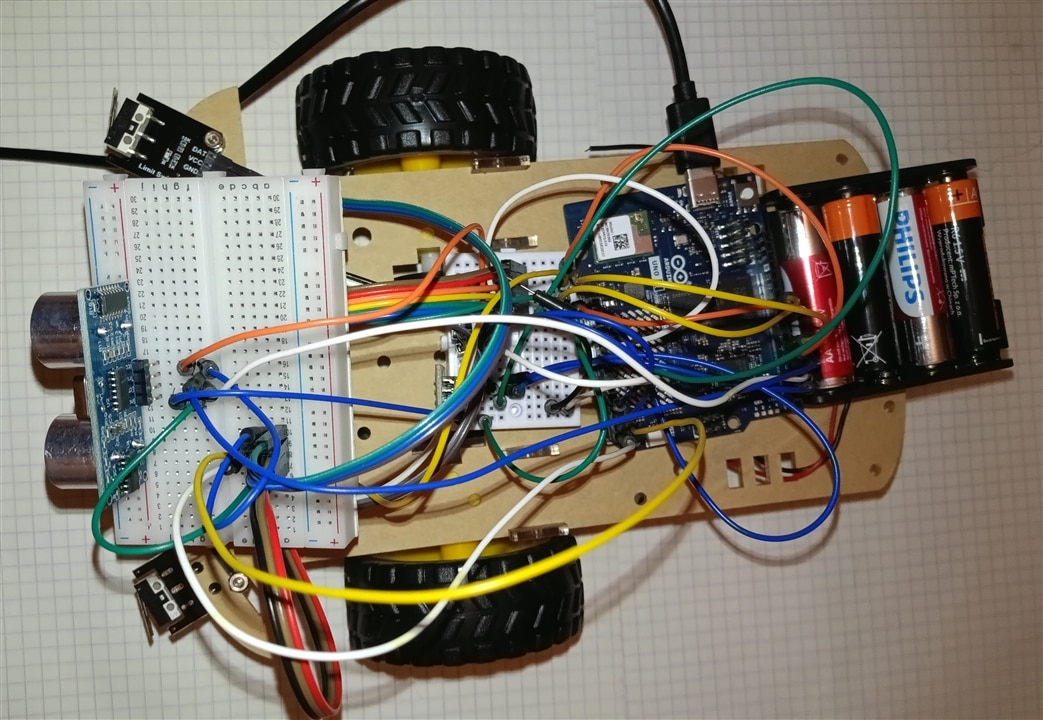
The primary addition is the support for physical collision sensors (bumpers) along with a 3-level safety hierarchy for handling obstacles.
1. Pin Definitions and Escape Speed
Explanation:// Physical Tactile Bumpers (Mapped to pins A4 and A5 on Arduino) const int COLLISION_PIN_L = 18; // Pin A4 const int COLLISION_PIN_R = 19; // Pin A5 const int ESCAPE_SPEED = 195; // Specific heavy escape/evasive speed vector
Added two new pins corresponding to the left (A4 / digital pin 18) and right (A5 / digital pin 19) physical collision microswitches/bumpers.
Defined ESCAPE_SPEED = 195, a dedicated motor speed used during longer backing-up and evasive maneuvers triggered by physical impacts.
2. Sensor Initialization in setup()
// Set as INPUT to match the original sponatenous logic of Elecrow modules
pinMode(COLLISION_PIN_L, INPUT);
pinMode(COLLISION_PIN_R, INPUT);
Explanation: Sets the bumper pins as standard digital inputs (INPUT). These modules send a high signal (HIGH / 1) to the pin when pressed.
3. Safety Hierarchy Logic in loop()
In autonomous mode (MODE_AUTONOMOUS), the code now executes operations based on a 3-level priority hierarchy:
Step 1: Read Bumper States (Binary Code)
int collisionState = (digitalRead(COLLISION_PIN_L) == HIGH ? 1 : 0) * 2 + (digitalRead(COLLISION_PIN_R) == HIGH ? 1 : 0);
Creates a bitwise variable collisionState with the following possible values:
-
0– No collision. -
1– Right-side collision. -
2– Left-side collision. -
3– Central collision (both bumpers pressed).
Priority 1: Physical Impact Response (Bumpers)
This is the top priority, handling cases where the robot has physically made contact with an obstacle (e.g., an object below the ultrasonic beam):
if (collisionState > 0) {
  Serial.print("TACTILE COLLISION TRIGGERED. Code: ");
  Serial.println(collisionState);

  switch (collisionState) {
    case 1: // Right collision -> Reverse for 2s, then turn left for 2s
      driveMotors(ESCAPE_SPEED, 0, ESCAPE_SPEED, 0); delay(2000);
      driveMotors(ESCAPE_SPEED, 0, 0, ESCAPE_SPEED); delay(2000);
      break;
    case 2: // Left collision -> Reverse for 2s, then turn right for 2s
      driveMotors(ESCAPE_SPEED, 0, ESCAPE_SPEED, 0); delay(2000);
      driveMotors(0, ESCAPE_SPEED, ESCAPE_SPEED, 0); delay(2000);
      break;
    case 3: // Central collision -> Reverse for 2s, then perform U-turn (left) for 2s
      driveMotors(ESCAPE_SPEED, 0, ESCAPE_SPEED, 0); delay(2000);
      driveMotors(ESCAPE_SPEED, 0, 0, ESCAPE_SPEED); delay(2000);
      break;
  }
}
Behavior: Upon impact, the robot reverses for 2 seconds, then spins away from the side of impact for 2 seconds to clear the obstacle.
Priority 2: Proactive Distance Check (HC-SR04 Sonar)
If no physical collision occurred (collisionState == 0), the code checks the ultrasonic rangefinder:
else if (distance < 30.0) {
  Serial.println("Obstacle detected by Sonar! Turning left...");
  driveMotors(MOTOR_SPEED, 0, 0, MOTOR_SPEED);
  delay(300);
}
Behavior: If an obstacle is detected within 30 cm, the robot performs a short left turn 30ms to steer around the obstacle before physical contact happens.
Priority 3: Line Following Routine
If there is no physical impact and no obstacles within 30cm, the robot falls back to standard line tracking logic (else { ... }).
Here is the complete, merged C program for the Arduino UNO Q, incorporating all features from all previous versions:
-
IR Remote Control
-
Line Tracking
-
HC-SR04 Ultrasonic Distance Sensor
-
Physical Tactile Collision Bumpers
-
Onboard RGB LED indicators (
LED3andLED4) -
8x13 LED Matrix Display (displaying directional arrows and the STOP icon)
#include <Arduino.h>
#include <Arduino_LED_Matrix.h> // Library for the 8x13 LED matrix

Arduino_LED_Matrix matrix; // Initialize LED matrix object

// L9110S Motor Driver Pins
const int MOTOR_PIN_A1 = 5;
const int MOTOR_PIN_A2 = 6;
const int MOTOR_PIN_B1 = 9;
const int MOTOR_PIN_B2 = 10;

// Infrared Receiver Pin
const int IR_RECEIVE_PIN = 2;

// Line Tracking Sensor Pins
const int TRACKING_PIN_L = A2;
const int TRACKING_PIN_R = A3;

// Ultrasonic HC-SR04 Sonar Pins
const int TRIG_PIN = 4;
const int ECHO_PIN = 3;

// Physical Tactile Bumpers
const int COLLISION_PIN_L = 18; // Pin A4
const int COLLISION_PIN_R = 19; // Pin A5

enum RobotMode {
  MODE_MANUAL,
  MODE_AUTONOMOUS
};

RobotMode currentMode = MODE_MANUAL;

// Speed settings
const int MOTOR_SPEED = 200;
const int ESCAPE_SPEED = 195; // Speed vector for escape maneuvers after collision
const int TRACK_SPEED = 160;

byte lastCommand = 0;

// LED Matrix Frame Buffer Size (104 pixels)
const uint8_t FRAME_SIZE = 8 * 13;

// --- LED MATRIX ARROW & ICON ARRAYS (Brightness levels 0-7) ---
uint8_t arrow_up[FRAME_SIZE] = {
    0, 0, 0, 0, 0, 0, 7, 0, 0, 0, 0, 0, 0,
    0, 0, 0, 0, 0, 7, 7, 7, 0, 0, 0, 0, 0,
    0, 0, 0, 0, 7, 7, 7, 7, 7, 0, 0, 0, 0,
    0, 0, 0, 7, 7, 0, 7, 0, 7, 7, 0, 0, 0,
    0, 0, 0, 0, 0, 0, 7, 0, 0, 0, 0, 0, 0,
    0, 0, 0, 0, 0, 0, 7, 0, 0, 0, 0, 0, 0,
    0, 0, 0, 0, 0, 0, 7, 0, 0, 0, 0, 0, 0,
    0, 0, 0, 0, 0, 0, 7, 0, 0, 0, 0, 0, 0
};

uint8_t arrow_down[FRAME_SIZE] = {
    0, 0, 0, 0, 0, 0, 7, 0, 0, 0, 0, 0, 0,
    0, 0, 0, 0, 0, 0, 7, 0, 0, 0, 0, 0, 0,
    0, 0, 0, 0, 0, 0, 7, 0, 0, 0, 0, 0, 0,
    0, 0, 0, 0, 0, 0, 7, 0, 0, 0, 0, 0, 0,
    0, 0, 0, 7, 7, 0, 7, 0, 7, 7, 0, 0, 0,
    0, 0, 0, 0, 7, 7, 7, 7, 7, 0, 0, 0, 0,
    0, 0, 0, 0, 0, 7, 7, 7, 0, 0, 0, 0, 0,
    0, 0, 0, 0, 0, 0, 7, 0, 0, 0, 0, 0, 0
};

uint8_t arrow_left[FRAME_SIZE] = {
    0, 0, 0, 0, 7, 0, 0, 0, 0, 0, 0, 0, 0,
    0, 0, 0, 7, 7, 0, 0, 0, 0, 0, 0, 0, 0,
    0, 0, 7, 7, 7, 7, 7, 7, 7, 7, 7, 7, 7,
    0, 7, 7, 7, 7, 7, 7, 7, 7, 7, 7, 7, 7,
    0, 7, 7, 7, 7, 7, 7, 7, 7, 7, 7, 7, 7,
    0, 0, 7, 7, 7, 7, 7, 7, 7, 7, 7, 7, 7,
    0, 0, 0, 7, 7, 0, 0, 0, 0, 0, 0, 0, 0,
    0, 0, 0, 0, 7, 0, 0, 0, 0, 0, 0, 0, 0
};

uint8_t arrow_right[FRAME_SIZE] = {
    0, 0, 0, 0, 0, 0, 0, 0, 7, 0, 0, 0, 0,
    0, 0, 0, 0, 0, 0, 0, 0, 7, 7, 0, 0, 0,
    7, 7, 7, 7, 7, 7, 7, 7, 7, 7, 7, 0, 0,
    7, 7, 7, 7, 7, 7, 7, 7, 7, 7, 7, 7, 0,
    7, 7, 7, 7, 7, 7, 7, 7, 7, 7, 7, 7, 0,
    7, 7, 7, 7, 7, 7, 7, 7, 7, 7, 7, 0, 0,
    0, 0, 0, 0, 0, 0, 0, 0, 7, 7, 0, 0, 0,
    0, 0, 0, 0, 0, 0, 0, 0, 7, 0, 0, 0, 0
};

uint8_t stop_icon[FRAME_SIZE] = { 0 };

// --- ONBOARD RGB LED FUNCTIONS ---
void set_led3_color(int r, int g, int b) {
  analogWrite(LED3_R, r);
  analogWrite(LED3_G, g);
  analogWrite(LED3_B, b);
}

void set_led4_color(bool r, bool g, bool b) {
  digitalWrite(LED4_R, r ? LOW : HIGH);
  digitalWrite(LED4_G, g ? LOW : HIGH);
  digitalWrite(LED4_B, b ? LOW : HIGH);
}

// Elecrow IR Decoder
long readElecrowIR() {
  int count = 0;
  while (digitalRead(IR_RECEIVE_PIN) == LOW && count < 200) { count++; delayMicroseconds(60); }
  if (count >= 200) return -1;

  count = 0;
  while (digitalRead(IR_RECEIVE_PIN) == HIGH && count < 80) { count++; delayMicroseconds(60); }
  if (count >= 80) return -1;

  int idx = 0, cnt = 0;
  byte data[4] = {0, 0, 0, 0};

  for (int i = 0; i < 32; i++) {
    count = 0;
    while (digitalRead(IR_RECEIVE_PIN) == LOW && count < 15) { count++; delayMicroseconds(60); }
    count = 0;
    while (digitalRead(IR_RECEIVE_PIN) == HIGH && count < 40) { count++; delayMicroseconds(60); }

    if (count > 8) data[idx] |= (1 << cnt);

    if (cnt == 7) { cnt = 0; idx++; } else { cnt++; }
  }

  if ((byte)(data[0] + data[1]) == 0xFF && (byte)(data[2] + data[3]) == 0xFF) {
    return data[2];
  }
  return -1;
}

void driveMotors(int a1, int a2, int b1, int b2) {
  analogWrite(MOTOR_PIN_A1, a1);
  analogWrite(MOTOR_PIN_A2, a2);
  analogWrite(MOTOR_PIN_B1, b1);
  analogWrite(MOTOR_PIN_B2, b2);
}

float getDistance() {
  digitalWrite(TRIG_PIN, LOW);
  delayMicroseconds(2);
  digitalWrite(TRIG_PIN, HIGH);
  delayMicroseconds(10);
  digitalWrite(TRIG_PIN, LOW);

  long duration = pulseIn(ECHO_PIN, HIGH, 30000);
  float d = duration * 0.0343 / 2;

  if (d == 0) return 999.0;
  return d;
}

void executeCommand(byte command) {
  switch (command) {
    case 0x1C: // OK Button - Toggle Manual/Autonomous operations
      if (currentMode == MODE_MANUAL) {
        currentMode = MODE_AUTONOMOUS;
        digitalWrite(LED_BUILTIN, HIGH);
        Serial.println("System Notification: AUTONOMY MODE ENGAGED.");
      }
      else {
        currentMode = MODE_MANUAL;
        digitalWrite(LED_BUILTIN, LOW);
        driveMotors(0, 0, 0, 0);
        set_led4_color(false, false, false);
        set_led3_color(0, 0, 0);
        matrix.draw(stop_icon);
        Serial.println("System Notification: MANUAL OVERRIDE ENGAGED.");
      }
      lastCommand = 0;
      delay(500);
      break;

    case 0x18: // Forward
      if (currentMode == MODE_MANUAL) {
        driveMotors(0, MOTOR_SPEED, 0, MOTOR_SPEED);
        set_led4_color(false, true, false); // Green
        set_led3_color(0, 200, 0);
        matrix.draw(arrow_up);
      }
      break;

    case 0x08: // Spin Left
      if (currentMode == MODE_MANUAL) {
        driveMotors(MOTOR_SPEED, 0, 0, MOTOR_SPEED);
        set_led4_color(false, false, true); // Blue
        set_led3_color(0, 0, 200);
        matrix.draw(arrow_left);
      }
      break;

    case 0x5A: // Spin Right
      if (currentMode == MODE_MANUAL) {
        driveMotors(0, MOTOR_SPEED, MOTOR_SPEED, 0);
        set_led4_color(false, false, true); // Blue
        set_led3_color(0, 0, 200);
        matrix.draw(arrow_right);
      }
      break;

    case 0x52: // Backward
      if (currentMode == MODE_MANUAL) {
        driveMotors(MOTOR_SPEED, 0, MOTOR_SPEED, 0);
        set_led4_color(true, false, false); // Red
        set_led3_color(200, 0, 0);
        matrix.draw(arrow_down);
      }
      break;

    default:
      if (currentMode == MODE_MANUAL) {
        driveMotors(0, 0, 0, 0);
        set_led4_color(false, false, false);
        set_led3_color(0, 0, 0);
        matrix.draw(stop_icon);
      }
      break;
  }
}

void setup() {
  Serial.begin(115200);

  pinMode(LED_BUILTIN, OUTPUT);
  digitalWrite(LED_BUILTIN, LOW);

  pinMode(IR_RECEIVE_PIN, INPUT_PULLUP);
  pinMode(TRACKING_PIN_L, INPUT_PULLUP);
  pinMode(TRACKING_PIN_R, INPUT_PULLUP);

  pinMode(TRIG_PIN, OUTPUT);
  pinMode(ECHO_PIN, INPUT);

  pinMode(COLLISION_PIN_L, INPUT);
  pinMode(COLLISION_PIN_R, INPUT);

  // RGB LED pin configuration
  pinMode(LED4_R, OUTPUT);
  pinMode(LED4_G, OUTPUT);
  pinMode(LED4_B, OUTPUT);
  set_led3_color(0, 0, 0);
  set_led4_color(false, false, false);

  // Initialize LED Matrix
  matrix.begin();
  matrix.setGrayscaleBits(3);
  matrix.clear();

  Serial.println("System Core Ready on Arduino UNO Q (IR + Line + Sonar + Bumpers + Display/LEDs).");
}

void loop() {
  // 1. Process incoming IR signals
  if (digitalRead(IR_RECEIVE_PIN) == LOW) {
    long result = readElecrowIR();
    if (result != -1) {
      lastCommand = (byte)result;
      executeCommand(lastCommand);
    }
  }

  // 2. Continuous Mode Execution
  if (currentMode == MODE_MANUAL) {
    if (digitalRead(IR_RECEIVE_PIN) == HIGH) {
      driveMotors(0, 0, 0, 0);
      set_led4_color(false, false, false);
      set_led3_color(0, 0, 0);
      matrix.draw(stop_icon);
    } else {
      executeCommand(lastCommand);
    }
  }
  else if (currentMode == MODE_AUTONOMOUS) {
    float distance = getDistance();
    int collisionState = (digitalRead(COLLISION_PIN_L) == HIGH ? 1 : 0) * 2 + (digitalRead(COLLISION_PIN_R) == HIGH ? 1 : 0);

    // --- HIERARCHY LEVEL 1: Physical Impact Interception (Bumpers) ---
    if (collisionState > 0) {
      Serial.print("TACTILE COLLISION TRIGGERED. Code: ");
      Serial.println(collisionState);

      set_led4_color(true, false, false); // Red alert
      set_led3_color(200, 0, 0);

      switch (collisionState) {
        case 1: // Right-side collision -> Reverse, then turn Left
          matrix.draw(arrow_down);
          driveMotors(ESCAPE_SPEED, 0, ESCAPE_SPEED, 0); delay(2000);
          matrix.draw(arrow_left);
          driveMotors(ESCAPE_SPEED, 0, 0, ESCAPE_SPEED); delay(2000);
          break;
        case 2: // Left-side collision -> Reverse, then turn Right
          matrix.draw(arrow_down);
          driveMotors(ESCAPE_SPEED, 0, ESCAPE_SPEED, 0); delay(2000);
          matrix.draw(arrow_right);
          driveMotors(0, ESCAPE_SPEED, ESCAPE_SPEED, 0); delay(2000);
          break;
        case 3: // Central collision -> Reverse, then U-Turn (Left)
          matrix.draw(arrow_down);
          driveMotors(ESCAPE_SPEED, 0, ESCAPE_SPEED, 0); delay(2000);
          matrix.draw(arrow_left);
          driveMotors(ESCAPE_SPEED, 0, 0, ESCAPE_SPEED); delay(2000);
          break;
      }
    }
    // --- HIERARCHY LEVEL 2: Proactive Clearance Monitoring (HC-SR04 Sonar) ---
    else if (distance < 30.0) {
      Serial.println("Obstacle detected by Sonar! Turning left...");
      driveMotors(MOTOR_SPEED, 0, 0, MOTOR_SPEED); // Evade Left
      set_led4_color(true, false, false);          // Red warning
      set_led3_color(200, 0, 0);
      matrix.draw(arrow_left);
      delay(300);
    }
    // --- HIERARCHY LEVEL 3: Standard Path Routine (Line Tracking) ---
    else {
      int trackL = digitalRead(TRACKING_PIN_L);
      int trackR = digitalRead(TRACKING_PIN_R);
      int trackState = (trackL * 2) + trackR;

      switch (trackState) {
        case 0: // Off track -> Stop
          driveMotors(0, 0, 0, 0);
          set_led4_color(false, false, false);
          set_led3_color(0, 0, 0);
          matrix.draw(stop_icon);
          break;

        case 1: // Right sensor active -> Turn Right
          driveMotors(0, TRACK_SPEED, TRACK_SPEED, 0);
          set_led4_color(false, false, true); // Blue
          set_led3_color(0, 0, 200);
          matrix.draw(arrow_right);
          break;

        case 2: // Left sensor active -> Turn Left
          driveMotors(TRACK_SPEED, 0, 0, TRACK_SPEED);
          set_led4_color(false, false, true); // Blue
          set_led3_color(0, 0, 200);
          matrix.draw(arrow_left);
          break;

        case 3: // Both sensors active -> Move Forward
          driveMotors(0, TRACK_SPEED, 0, TRACK_SPEED);
          set_led4_color(false, true, false); // Green
          set_led3_color(0, 200, 0);
          matrix.draw(arrow_up);
          break;
      }
      delay(10);
    }
  }
}
7. Mobile Robot Control and Live Video Streaming
As part of this project, we have developed a fully wireless control system for a wheeled robot integrated with a real-time live video stream. The heart of the entire setup is the Arduino Uno Q board.
Architecture and Technologies Used
The project leverages the unique, dual-processor architecture of the Arduino Uno Q and the Arduino App Lab ecosystem, which allows splitting system operations into two separate layers:
1. Application Layer (MPU Processor running Linux/Zephyr):
- Responsible for directly handling the USB camera plugged into the board's port.
- Runs a native server hosting the Web User Interface (WebUI).
- Streams live video directly to any web browser in real-time, completely bypassing the need for heavy external libraries like Flask or OpenCV.
2. Hardware Layer (MCU STM32 Microcontroller):
- Handles real-time, low-level execution of the digital H-bridge pins (four input pins controlling motor direction).
- Generates diagnostic signals for the onboard peripherals of the Arduino Uno Q.
The engineered system seamlessly combines mechanical movement with advanced visual telemetry broadcasted directly on the robot itself:
1. Virtual Joystick (Local WebUI): The web interface is completely free of external network dependencies (no CDNs, no Cloudflare). The entire touch-control script is embedded directly into the index.html file within the assets folder. Touch drags on a smartphone screen or mouse movements on a PC are instantly calculated into directional vectors (F - forward, B - backward, L - left, R - right, S - stop).
2. Inter-Process Communication (RPC Bridge): To transmit data from the web interface (JavaScript/Python code) to the motors (C++ code), we used the official, built-in Arduino_RouterBridge communication bridge. It handles asynchronous requests, guaranteeing minimal latency and instantaneous drive response.
3. Color Status Signaling (RGB LED): The system integrates the native mapping of the onboard LED4, which operates in an inverted logic state (Active LOW). When moving forward, the LED lights up green; when reversing, it turns red; during turns, it lights up blue; and it automatically turns off when the robot is idle.
4. 8×13 Directional LED Matrix: The large LED dot matrix embedded into the Arduino Uno Q is used to visualize the robot's heading. Utilizing the low-level matrix.draw() function and raw pixel bitmaps (104-byte arrays defining pixel brightness on a 0–7 scale), the matrix renders crisp, bright arrows (▲, ▼, <, >) in real-time corresponding to the active drive direction.
By strictly utilizing the native libraries of the Arduino App Lab ecosystem (arduino.app_bricks.web_ui and Arduino_LED_Matrix), this solution boasts exceptional stability:It completely eliminates compilation errors related to memory pointer casting during array parsing.It ensures total offline independence – the robot operates entirely within a local Wi-Fi network.The codebase serves as a production-ready template for Smart Assist EV applications and autonomous inspection platforms.
To run the entire system, you need an external USB hub with a USB-C plug that connects to the Arduino Uno Q, featuring USB-C Power Delivery ports and USB 2.0 or USB 3.0 ports to connect a USB camera.
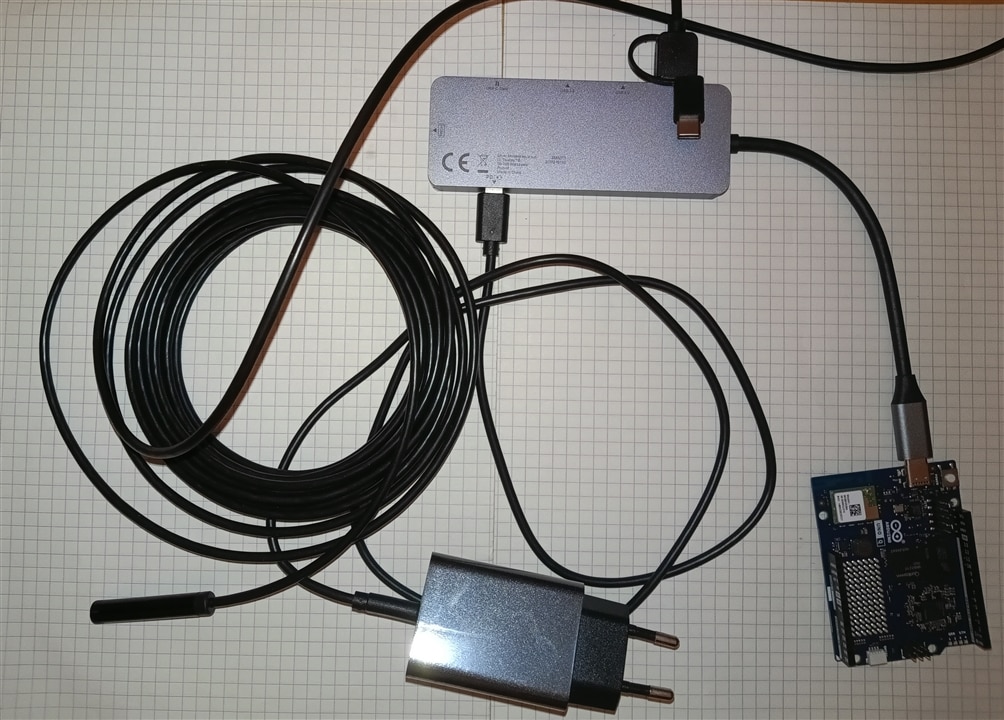
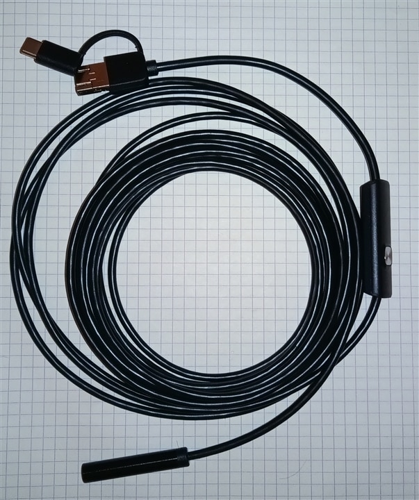
I tested several cameras. Unfortunately, some of them do not work properly with the Arduino Q. Despite my efforts, I could not get the rather old Megapixel USB2 Webcam Live WB-5400 - 15007 (which runs on USB 2.0) to work. The project uses a 3-in-1 Waterproof USB Endoscope Inspection Camera. The integrated ultra-bright LEDs and 1200P HD camera make it able to present images with a color effect while retaining high resolution and quality even in dark places. In addition, the lens is equipped with automatic exposure and blue light technology, which can effectively filter stray light, restore real scenes, and make images clearer.
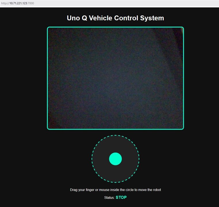
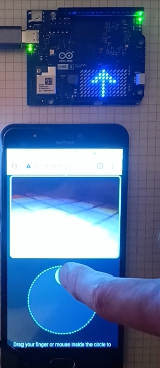
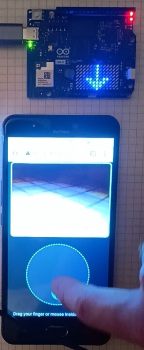
A web page containing a camera feed along with a joystick can be displayed on a computer or a mobile device. This offers tremendous possibilities for the user, allowing them to control the vehicle not only locally from an apartment but also remotely. The view of the page is shown in the image. After refreshing the page in your phone/computer browser: Below the video window, you will see a dark gray circle with a dashed light blue border. When you click or tap inside this circle, a light blue, movable joystick will immediately appear there, allowing you to control the vehicle.
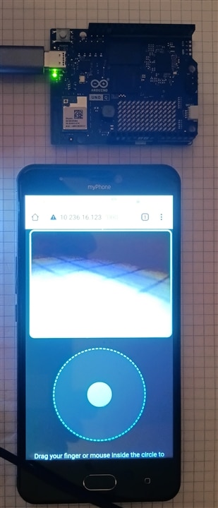
The image below shows the website running on a smartphone. As you can see, there's no need to create and install a dedicated app—a standard web browser will suffice.
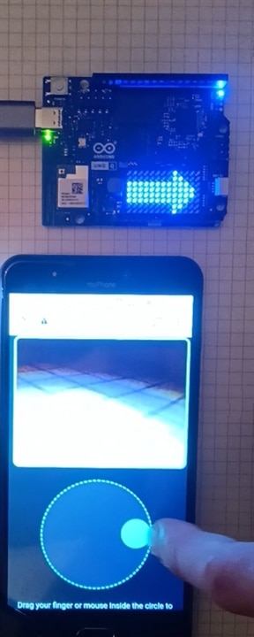
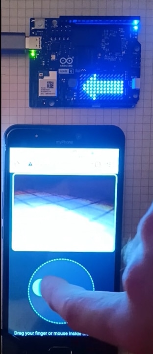
For diagnostic purposes, the built-in LEDs on the Arduino Uno board were used to indicate the vehicle's status: a lit blue LED indicates turning left or right, green indicates moving forward, and red indicates moving backward. Additionally, the matrix display shows arrows indicating the direction in which the vehicle is moving.
You can also watch a video showing how the website works on YouTube:
https://www.youtube.com/watch?v=E3mmpFuwCU4
Firmware Implementation: Motor Control and RPC Communication
1. Libraries and System Architecture
#include <Arduino_RouterBridge.h> // Official RPC header for Uno Q
#include <Arduino_LED_Matrix.h>   // 8x13 Matrix library

Arduino_LED_Matrix matrix; // Initialize the LED matrix

    <Arduino_RouterBridge.h>: The official Remote Procedure Call (RPC) library for the Arduino UNO Q. It establishes a communication bridge between the microcontroller unit (MCU) running C++ and the Linux host system running Python (main.py).

    <Arduino_LED_Matrix.h>: The library used to control the built-in 8×13 LED matrix display.

    Arduino_LED_Matrix matrix;: Instantiates the matrix driver object to draw graphical frames.
2. Pin Mapping and Constants
// Motor pin definitions for Elecrow kit (H-bridges)
const int MOTOR_L_F = 4;
const int MOTOR_L_B = 5;
const int MOTOR_R_F = 6;
const int MOTOR_R_B = 7;

const uint8_t FRAME_SIZE = 8 * 13; // 104 pixels

    Motor Pins:

        MOTOR_L_F (Pin 4) & MOTOR_L_B (Pin 5): Left motor forward and backward channels.

        MOTOR_R_F (Pin 6) & MOTOR_R_B (Pin 7): Right motor forward and backward channels.

    FRAME_SIZE = 8 * 13: Defines the total pixel array size (104 pixels) for the LED matrix.
3. LED Matrix Graphic Data Arrays
// 1. UP ARROW (FORWARD)
uint8_t arrow_up[FRAME_SIZE] = {
    0, 0, 0, 0, 0, 0, 7, 0, 0, 0, 0, 0, 0,
    0, 0, 0, 0, 0, 7, 7, 7, 0, 0, 0, 0, 0,
    0, 0, 0, 0, 7, 7, 7, 7, 7, 0, 0, 0, 0,
    0, 0, 0, 7, 7, 0, 7, 0, 7, 7, 0, 0, 0,
    0, 0, 0, 0, 0, 0, 7, 0, 0, 0, 0, 0, 0,
    0, 0, 0, 0, 0, 0, 7, 0, 0, 0, 0, 0, 0,
    0, 0, 0, 0, 0, 0, 7, 0, 0, 0, 0, 0, 0,
    0, 0, 0, 0, 0, 0, 7, 0, 0, 0, 0, 0, 0
};

// 5. CLEAR DISPLAY (STOP)
uint8_t stop_icon[FRAME_SIZE] = { 0 }; // All pixels off (value 0)
Four 1D byte arrays (arrow_up, arrow_down, arrow_left, arrow_right) and one blank array (stop_icon) represent visual icons.
Grayscale Value Mapping: Each index corresponds to one pixel. Values range from 0 (LED completely off) to 7 (maximum LED brightness).
The visual layout inside the code mimics the 8×13 grid structure to visualize arrow shapes directly in the source file.
4. Helper Functions
set_led4_color(bool r, bool g, bool b)
// Function controlling the built-in LED4 using inverted logic
void set_led4_color(bool r, bool g, bool b) {
  digitalWrite(LED4_R, r ? LOW : HIGH);
  digitalWrite(LED4_G, g ? LOW : HIGH);
  digitalWrite(LED4_B, b ? LOW : HIGH);
}
Controls the onboard RGB LED (LED4).
Active-Low Logic: The pins use inverted logic. Setting a pin to LOW turns the corresponding color component ON, whereas setting it to HIGH turns it OFF (handled via ternary operators r ? LOW : HIGH).
move_robot_mcu(String direction)
// Function receiving commands from the web page (via RPC bridge)
void move_robot_mcu(String direction) {
  if (direction == "F") { // FORWARD
    digitalWrite(MOTOR_L_F, HIGH); digitalWrite(MOTOR_R_F, HIGH);
    digitalWrite(MOTOR_L_B, LOW);  digitalWrite(MOTOR_R_B, LOW);

    set_led4_color(false, true, false); // GREEN
    matrix.draw(arrow_up);               // Display up arrow
  }
  else if (direction == "B") { // BACKWARD
    digitalWrite(MOTOR_L_F, LOW);  digitalWrite(MOTOR_R_F, LOW);
    digitalWrite(MOTOR_L_B, HIGH); digitalWrite(MOTOR_R_B, HIGH);

    set_led4_color(true, false, false); // RED
    matrix.draw(arrow_down);             // Display down arrow
  }
  // ... (additional conditions for "L" and "R")
  else { // STOP ("S")
    digitalWrite(MOTOR_L_F, LOW);  digitalWrite(MOTOR_L_B, LOW);
    digitalWrite(MOTOR_R_F, LOW);  digitalWrite(MOTOR_R_B, LOW);

    set_led4_color(false, false, false); // Turn off RGB LED
    matrix.draw(stop_icon);               // Clear LED matrix
  }
}
The primary execution function triggered via the RPC bridge. It handles drive state, RGB lighting, and matrix rendering simultaneously:
| Input Signal | Action | H-Bridge Motor Pin States | RGB Color | Matrix Graphic |
"F" |
Forward | L_F: HIGH, R_F: HIGH, L_B: LOW, R_B: LOW |
Green | arrow_up |
"B" |
Backward | L_F: LOW, R_F: LOW, L_B: HIGH, R_B: HIGH |
Red | arrow_down |
"L" |
Spin Left | L_F: LOW, R_F: HIGH, L_B: HIGH, R_B: LOW |
Blue | arrow_left |
"R" |
Spin Right | L_F: HIGH, R_F: LOW, L_B: LOW, R_B: HIGH |
Blue | arrow_right |
Else / "S" |
Stop | All motor pins LOW |
Off | stop_icon (Clear) |
5. Program Initialization (setup)
void setup() {
  // Initialize onboard RGB LED4
  pinMode(LED4_R, OUTPUT);
  pinMode(LED4_G, OUTPUT);
  pinMode(LED4_B, OUTPUT);
  set_led4_color(false, false, false);

  // Initialize matrix hardware
  matrix.begin();
  matrix.setGrayscaleBits(3); // Brightness levels from 0 to 7
  matrix.clear();

  // Start the official Linux communication bridge (main.py)
  Bridge.begin();
  Bridge.provide("drive", move_robot_mcu);

  // Initialize motor H-bridge control pins
  pinMode(MOTOR_L_F, OUTPUT); pinMode(MOTOR_L_B, OUTPUT);
  pinMode(MOTOR_R_F, OUTPUT); pinMode(MOTOR_R_B, OUTPUT);

  move_robot_mcu("S"); // Initial state (Vehicle stopped, matrix cleared)
}
RGB LED Setup: Configures LED4_R, LED4_G, and LED4_B as output pins and initializes them to an off state.
Matrix Initialization: Starts the display hardware using matrix.begin(), sets brightness resolution to 3 bits (0-7 scale) via matrix.setGrayscaleBits(3), and clears any leftover pixels.
RPC Bridge Exposure:
Bridge.begin() starts the Linux-MCU communication.
Bridge.provide("drive", move_robot_mcu); registers the move_robot_mcu function under the RPC service name "drive". This allows external Linux scripts or web applications to execute this C++ function remotely over RPC.
Motor Pin Modes: Sets all motor control pins as outputs and enforces an initial STOP state (move_robot_mcu("S")).
6. Main Execution Loop (loop)
void loop() {
  // Empty loop - RPC command handling occurs automatically in the background
  delay(10);
}
The loop() body is intentionally kept empty, containing only a small delay (delay(10)).
Asynchronous Execution: Incoming commands sent from a smartphone, web interface, or Python script are handled in the background by the Arduino_RouterBridge middleware without blocking the main program thread.
Here is the complete project, fully adapted to the native environment of Arduino App Lab, configured for the Elecrow car kit.
#include <Arduino_RouterBridge.h> // Official RPC header for Uno Q
#include <Arduino_LED_Matrix.h>   // 8x13 matrix library

Arduino_LED_Matrix matrix; // Initialize the large matrix

// Motor pin definitions for the Elecrow kit (H-bridges)
const int MOTOR_L_F = 4;
const int MOTOR_L_B = 5;
const int MOTOR_R_F = 6;
const int MOTOR_R_B = 7;

const uint8_t FRAME_SIZE = 8 * 13; // 104 pixels

// 1. UP ARROW (FORWARD)
uint8_t arrow_up[FRAME_SIZE] = {
    0, 0, 0, 0, 0, 0, 7, 0, 0, 0, 0, 0, 0,
    0, 0, 0, 0, 0, 7, 7, 7, 0, 0, 0, 0, 0,
    0, 0, 0, 0, 7, 7, 7, 7, 7, 0, 0, 0, 0,
    0, 0, 0, 7, 7, 0, 7, 0, 7, 7, 0, 0, 0,
    0, 0, 0, 0, 0, 0, 7, 0, 0, 0, 0, 0, 0,
    0, 0, 0, 0, 0, 0, 7, 0, 0, 0, 0, 0, 0,
    0, 0, 0, 0, 0, 0, 7, 0, 0, 0, 0, 0, 0,
    0, 0, 0, 0, 0, 0, 7, 0, 0, 0, 0, 0, 0
};

// 2. DOWN ARROW (BACKWARD)
uint8_t arrow_down[FRAME_SIZE] = {
    0, 0, 0, 0, 0, 0, 7, 0, 0, 0, 0, 0, 0,
    0, 0, 0, 0, 0, 0, 7, 0, 0, 0, 0, 0, 0,
    0, 0, 0, 0, 0, 0, 7, 0, 0, 0, 0, 0, 0,
    0, 0, 0, 0, 0, 0, 7, 0, 0, 0, 0, 0, 0,
    0, 0, 0, 7, 7, 0, 7, 0, 7, 7, 0, 0, 0,
    0, 0, 0, 0, 7, 7, 7, 7, 7, 0, 0, 0, 0,
    0, 0, 0, 0, 0, 7, 7, 7, 0, 0, 0, 0, 0,
    0, 0, 0, 0, 0, 0, 7, 0, 0, 0, 0, 0, 0
};

// 3. LEFT ARROW
uint8_t arrow_left[FRAME_SIZE] = {
    0, 0, 0, 0, 7, 0, 0, 0, 0, 0, 0, 0, 0,
    0, 0, 0, 7, 7, 0, 0, 0, 0, 0, 0, 0, 0,
    0, 0, 7, 7, 7, 7, 7, 7, 7, 7, 7, 7, 7,
    0, 7, 7, 7, 7, 7, 7, 7, 7, 7, 7, 7, 7,
    0, 7, 7, 7, 7, 7, 7, 7, 7, 7, 7, 7, 7,
    0, 0, 7, 7, 7, 7, 7, 7, 7, 7, 7, 7, 7,
    0, 0, 0, 7, 7, 0, 0, 0, 0, 0, 0, 0, 0,
    0, 0, 0, 0, 7, 0, 0, 0, 0, 0, 0, 0, 0
};

// 4. RIGHT ARROW
uint8_t arrow_right[FRAME_SIZE] = {
    0, 0, 0, 0, 0, 0, 0, 0, 7, 0, 0, 0, 0,
    0, 0, 0, 0, 0, 0, 0, 0, 7, 7, 0, 0, 0,
    7, 7, 7, 7, 7, 7, 7, 7, 7, 7, 7, 0, 0,
    7, 7, 7, 7, 7, 7, 7, 7, 7, 7, 7, 7, 0,
    7, 7, 7, 7, 7, 7, 7, 7, 7, 7, 7, 7, 0,
    7, 7, 7, 7, 7, 7, 7, 7, 7, 7, 0, 0,
    0, 0, 0, 0, 0, 0, 0, 0, 7, 7, 0, 0, 0,
    0, 0, 0, 0, 0, 0, 0, 0, 7, 0, 0, 0, 0
};

// 5. CLEAR DISPLAY (STOP)
uint8_t stop_icon[FRAME_SIZE] = { 0 }; // All pixels off (value 0)

// Function controlling the built-in LED4 using inverted logic
void set_led4_color(bool r, bool g, bool b) {
  digitalWrite(LED4_R, r ? LOW : HIGH);
  digitalWrite(LED4_G, g ? LOW : HIGH);
  digitalWrite(LED4_B, b ? LOW : HIGH);
}

// Function receiving commands from the web page (via RPC bridge)
void move_robot_mcu(String direction) {
  if (direction == "F") { // FORWARD
    digitalWrite(MOTOR_L_F, HIGH); digitalWrite(MOTOR_R_F, HIGH);
    digitalWrite(MOTOR_L_B, LOW);  digitalWrite(MOTOR_R_B, LOW);

    set_led4_color(false, true, false); // GREEN
    matrix.draw(arrow_up);               // Display up arrow
  }
  else if (direction == "B") { // BACKWARD
    digitalWrite(MOTOR_L_F, LOW);  digitalWrite(MOTOR_R_F, LOW);
    digitalWrite(MOTOR_L_B, HIGH); digitalWrite(MOTOR_R_B, HIGH);

    set_led4_color(true, false, false); // RED
    matrix.draw(arrow_down);             // Display down arrow
  }
  else if (direction == "L") { // LEFT
    digitalWrite(MOTOR_L_F, LOW);  digitalWrite(MOTOR_R_F, HIGH);
    digitalWrite(MOTOR_L_B, HIGH); digitalWrite(MOTOR_R_B, LOW);

    set_led4_color(false, false, true); // BLUE
    matrix.draw(arrow_left);             // Display left arrow
  }
  else if (direction == "R") { // RIGHT
    digitalWrite(MOTOR_L_F, HIGH); digitalWrite(MOTOR_R_F, LOW);
    digitalWrite(MOTOR_L_B, LOW);  digitalWrite(MOTOR_R_B, HIGH);

    set_led4_color(false, false, true); // BLUE
    matrix.draw(arrow_right);            // Display right arrow
  }
  else { // STOP ("S")
    digitalWrite(MOTOR_L_F, LOW);  digitalWrite(MOTOR_L_B, LOW);
    digitalWrite(MOTOR_R_F, LOW);  digitalWrite(MOTOR_R_B, LOW);

    set_led4_color(false, false, false); // Turn off RGB LED
    matrix.draw(stop_icon);               // Clear LED matrix
  }
}

void setup() {
  // Initialize built-in LED4
  pinMode(LED4_R, OUTPUT);
  pinMode(LED4_G, OUTPUT);
  pinMode(LED4_B, OUTPUT);
  set_led4_color(false, false, false);

  // Initialize the matrix exactly as in the working example
  matrix.begin();
  matrix.setGrayscaleBits(3); // Brightness levels from 0 to 7
  matrix.clear();

  // Start the official communication bridge with Linux (main.py)
  Bridge.begin();
  Bridge.provide("drive", move_robot_mcu);

  // Initialize control pins for motor H-bridges
  pinMode(MOTOR_L_F, OUTPUT); pinMode(MOTOR_L_B, OUTPUT);
  pinMode(MOTOR_R_F, OUTPUT); pinMode(MOTOR_R_B, OUTPUT);

  move_robot_mcu("S"); // Initial state (Vehicle stopped, matrix off)
}

void loop() {
  // Empty loop - handling RPC commands from the phone happens automatically in the background
  delay(10);
}
#include <Arduino.h>
#include <Arduino_RouterBridge.h> // Official RPC header for Uno Q
#include <Arduino_LED_Matrix.h>   // Library for the 8x13 LED matrix

Arduino_LED_Matrix matrix; // Initialize the large LED matrix

// --- HARDWARE PIN CONFIGURATION ---
const int motorPinA_1A = 5;
const int motorPinA_1B = 6;
const int motorPinB_1A = 9;
const int motorPinB_1B = 10;

const int IR_RECEIVE_PIN = 2;
const int trigPin = 4;
const int echoPin = 3;

// Physical Tactile Bumpers
const int CollisionPin_L = 18; // Pin A4
const int CollisionPin_R = 19; // Pin A5

// Line Tracking Photo-interrupters
const int TrackingPin_L = A2;
const int TrackingPin_R = A3;

// --- ROBOT PARAMETERS AND MODES ---
enum RobotMode { MODE_MANUAL, MODE_AUTONOMOUS };
RobotMode currentMode = MODE_MANUAL;

const int motorSpeed = 200;
int spd = 195; // Specific heavy escape/evasive speed vector
int trackSpeed = 160; // Optimized track following velocity for Uno Q

unsigned long lastCommandTime = 0;
const unsigned long commandTimeout = 250;
const uint8_t FRAME_SIZE = 8 * 13; // 104 pixels for the LED matrix
byte lastCommand = 0;

// --- LED MATRIX ARROW ARRAYS (Brightness levels 0-7) ---
uint8_t arrow_up[FRAME_SIZE] = {
 0, 0, 0, 0, 0, 0, 7, 0, 0, 0, 0, 0, 0,
 0, 0, 0, 0, 0, 7, 7, 7, 0, 0, 0, 0, 0,
 0, 0, 0, 0, 7, 7, 7, 7, 7, 0, 0, 0, 0,
 0, 0, 0, 7, 7, 0, 7, 0, 7, 7, 0, 0, 0,
 0, 0, 0, 0, 0, 0, 7, 0, 0, 0, 0, 0, 0,
 0, 0, 0, 0, 0, 0, 7, 0, 0, 0, 0, 0, 0,
 0, 0, 0, 0, 0, 0, 7, 0, 0, 0, 0, 0, 0,
 0, 0, 0, 0, 0, 0, 7, 0, 0, 0, 0, 0, 0
};
uint8_t arrow_down[FRAME_SIZE] = {
 0, 0, 0, 0, 0, 0, 7, 0, 0, 0, 0, 0, 0,
 0, 0, 0, 0, 0, 0, 7, 0, 0, 0, 0, 0, 0,
 0, 0, 0, 0, 0, 0, 7, 0, 0, 0, 0, 0, 0,
 0, 0, 0, 0, 0, 0, 7, 0, 0, 0, 0, 0, 0,
 0, 0, 0, 7, 7, 0, 7, 0, 7, 7, 0, 0, 0,
 0, 0, 0, 0, 7, 7, 7, 7, 7, 0, 0, 0, 0,
 0, 0, 0, 0, 0, 7, 7, 7, 0, 0, 0, 0, 0,
 0, 0, 0, 0, 0, 0, 7, 0, 0, 0, 0, 0, 0
};
uint8_t arrow_left[FRAME_SIZE] = {
 0, 0, 0, 0, 7, 0, 0, 0, 0, 0, 0, 0, 0,
 0, 0, 0, 7, 7, 0, 0, 0, 0, 0, 0, 0, 0,
 0, 0, 7, 7, 7, 7, 7, 7, 7, 7, 7, 7, 7,
 0, 7, 7, 7, 7, 7, 7, 7, 7, 7, 7, 7, 7,
 0, 7, 7, 7, 7, 7, 7, 7, 7, 7, 7, 7, 7,
 0, 0, 7, 7, 7, 7, 7, 7, 7, 7, 7, 7, 7,
 0, 0, 0, 7, 7, 0, 0, 0, 0, 0, 0, 0, 0,
 0, 0, 0, 0, 7, 0, 0, 0, 0, 0, 0, 0, 0
};
uint8_t arrow_right[FRAME_SIZE] = {
 0, 0, 0, 0, 0, 0, 0, 0, 7, 0, 0, 0, 0,
 0, 0, 0, 0, 0, 0, 0, 0, 7, 7, 0, 0, 0,
 7, 7, 7, 7, 7, 7, 7, 7, 7, 7, 7, 0, 0,
 7, 7, 7, 7, 7, 7, 7, 7, 7, 7, 7, 7, 0,
 7, 7, 7, 7, 7, 7, 7, 7, 7, 7, 7, 7, 0,
 7, 7, 7, 7, 7, 7, 7, 7, 7, 7, 7, 0, 0,
 0, 0, 0, 0, 0, 0, 0, 0, 7, 7, 0, 0, 0,
 0, 0, 0, 0, 0, 0, 0, 0, 7, 0, 0, 0, 0
};
uint8_t stop_icon[FRAME_SIZE] = { 0 };

// --- ONBOARD RGB LED CONTROL FUNCTIONS ---
void set_led3_color(int r, int g, int b) {
 analogWrite(LED3_R, r);
 analogWrite(LED3_G, g);
 analogWrite(LED3_B, b);
}
void set_led4_color(bool r, bool g, bool b) {
 digitalWrite(LED4_R, r ? LOW : HIGH);
 digitalWrite(LED4_G, g ? LOW : HIGH);
 digitalWrite(LED4_B, b ? LOW : HIGH);
}

// --- MOTOR DRIVE DRIVER ---
void motor(int A1, int A2, int B1, int B2) {
 analogWrite(motorPinA_1A, A1);
 analogWrite(motorPinA_1B, A2);
 analogWrite(motorPinB_1A, B1);
 analogWrite(motorPinB_1B, B2);
}

// --- NATIVE IR DECODER FOR ARDUINO UNO Q ---
long readElecrowIR() {
  int count = 0;
  while (digitalRead(IR_RECEIVE_PIN) == LOW && count < 200) {
    count++;
    delayMicroseconds(60);
  }
  if (count >= 200) return -1;

  count = 0;
  while (digitalRead(IR_RECEIVE_PIN) == HIGH && count < 80) {
    count++;
    delayMicroseconds(60);
  }
  if (count >= 80) return -1;

  int idx = 0;
  int cnt = 0;
  byte data[4] = {0, 0, 0, 0};

  for (int i = 0; i < 32; i++) {
    count = 0;
    while (digitalRead(IR_RECEIVE_PIN) == LOW && count < 15) {
      count++;
      delayMicroseconds(60);
    }
    count = 0;
    while (digitalRead(IR_RECEIVE_PIN) == HIGH && count < 40) {
      count++;
      delayMicroseconds(60);
    }
    if (count > 8) {
      data[idx] |= (1 << cnt);
    }
    if (cnt == 7) {
      cnt = 0;
      idx++;
    } else {
      cnt++;
    }
  }

  if ((byte)(data[0] + data[1]) == 0xFF && (byte)(data[2] + data[3]) == 0xFF) {
    return data[2];
  }
  return -1;
}

// --- WEB INTERFACE INTERCEPTOR (FIXED: Changed argument type to String) ---
void move_robot_mcu(String direction) {
 if (currentMode != MODE_MANUAL) return;

 if (direction == "F") {
 motor(0, motorSpeed, 0, motorSpeed);
 set_led4_color(false, true, false);
 set_led3_color(0, 200, 0);
 matrix.draw(arrow_up);
 }
 else if (direction == "B") {
 motor(motorSpeed, 0, motorSpeed, 0);
 set_led4_color(true, false, false);
 set_led3_color(200, 0, 0);
 matrix.draw(arrow_down);
 }
 else if (direction == "L") {
 motor(motorSpeed, 0, 0, motorSpeed);
 set_led4_color(false, false, true);
 set_led3_color(0, 0, 200);
 matrix.draw(arrow_left);
 }
 else if (direction == "R") {
 motor(0, motorSpeed, motorSpeed, 0);
 set_led4_color(false, false, true);
 set_led3_color(0, 0, 200);
 matrix.draw(arrow_right);
 }
 else {
 motor(0, 0, 0, 0);
 set_led4_color(false, false, false);
 set_led3_color(0, 0, 0);
 matrix.draw(stop_icon);
 }
}

float getDistance() {
 digitalWrite(trigPin, LOW);
 delayMicroseconds(2);
 digitalWrite(trigPin, HIGH);
 delayMicroseconds(10);
 digitalWrite(trigPin, LOW);

 long duration = pulseIn(echoPin, HIGH, 30000);
 float d = duration * 0.0343 / 2;
 if (d == 0) return 999.0;
 return d;
}

// --- WEB MODE TOGGLE (FIXED: Changed argument type to String) ---
void toggle_mode_from_web(String cmd) {
 if (currentMode == MODE_MANUAL) {
 currentMode = MODE_AUTONOMOUS;
 set_led3_color(200, 200, 0);
 Serial.println("System Notification: AUTONOMY MODE ENGAGED VIA WEB.");
 } else {
 currentMode = MODE_MANUAL;
 motor(0, 0, 0, 0);
 set_led3_color(0, 0, 0);
 matrix.draw(stop_icon);
 Serial.println("System Notification: MANUAL OVERRIDE ENGAGED VIA WEB.");
 }
}

void exec_cmd(byte key_val) {
 switch (key_val) {
 case 0x1C:
 if (currentMode == MODE_MANUAL) {
 currentMode = MODE_AUTONOMOUS;
 set_led3_color(200, 200, 0);
 Serial.println("System Notification: AUTONOMY MODE ENGAGED.");
 } else {
 currentMode = MODE_MANUAL;
 motor(0, 0, 0, 0);
 set_led3_color(0, 0, 0);
 matrix.draw(stop_icon);
 Serial.println("System Notification: MANUAL OVERRIDE ENGAGED.");
 }
 lastCommand = 0;
 delay(500);
 break;
 case 0x18: if (currentMode == MODE_MANUAL) { motor(0, motorSpeed, 0, motorSpeed); matrix.draw(arrow_up); } break;
 case 0x08: if (currentMode == MODE_MANUAL) { motor(motorSpeed, 0, 0, motorSpeed); matrix.draw(arrow_left); } break;
 case 0x5A: if (currentMode == MODE_MANUAL) { motor(0, motorSpeed, motorSpeed, 0); matrix.draw(arrow_right); } break;
 case 0x52: if (currentMode == MODE_MANUAL) { motor(motorSpeed, 0, motorSpeed, 0); matrix.draw(arrow_down); } break;
 default: if (currentMode == MODE_MANUAL) { motor(0, 0, 0, 0); matrix.draw(stop_icon); } break;
 }
}

void setup() {
 Serial.begin(115200);

 pinMode(IR_RECEIVE_PIN, INPUT_PULLUP);
 pinMode(trigPin, OUTPUT);
 pinMode(echoPin, INPUT);
 pinMode(CollisionPin_L, INPUT);
 pinMode(CollisionPin_R, INPUT);
 pinMode(TrackingPin_L, INPUT_PULLUP);
 pinMode(TrackingPin_R, INPUT_PULLUP);

 pinMode(LED4_R, OUTPUT); pinMode(LED4_G, OUTPUT); pinMode(LED4_B, OUTPUT);
 set_led3_color(0, 0, 0);
 set_led4_color(false, false, false);
 matrix.begin();
 matrix.setGrayscaleBits(3);
 matrix.clear();

 // --- RPC BRIDGE REGISTRATION ---
 Bridge.begin();
 Bridge.provide("drive", move_robot_mcu);
 Bridge.provide("toggle_mode", toggle_mode_from_web);

 Serial.println("System Core Ready.");
}

void loop() {
  // 1. IR Remote control handling
  if (digitalRead(IR_RECEIVE_PIN) == LOW) {
    long result = readElecrowIR();
    if (result != -1) {
      lastCommand = (byte)result;
      exec_cmd(lastCommand);
      if (currentMode == MODE_MANUAL) lastCommandTime = millis();
    }
  }

  // 2. Motion modes execution logic
  if (currentMode == MODE_MANUAL) {
    if (digitalRead(IR_RECEIVE_PIN) == HIGH) {
      if (millis() - lastCommandTime > commandTimeout) {
        motor(0, 0, 0, 0);
      }
    } else {
      exec_cmd(lastCommand);
    }
  }
  else if (currentMode == MODE_AUTONOMOUS) {
    float distance = getDistance();
    int sumVal = (digitalRead(CollisionPin_L) == HIGH ? 1 : 0) * 2 + (digitalRead(CollisionPin_R) == HIGH ? 1 : 0);

    // --- HIERARCHY 1: Physical Bumpers ---
    if (sumVal > 0) {
      Serial.print("TACTILE COLLISION TRIGGERED. Code: ");
      Serial.println(sumVal);
      matrix.draw(stop_icon);

      if (sumVal == 1) {
        motor(spd, 0, spd, 0); delay(2000);
        motor(spd, 0, 0, spd); delay(2000);
      }
      else if (sumVal == 2) {
        motor(spd, 0, spd, 0); delay(2000);
        motor(0, spd, spd, 0); delay(2000);
      }
      else if (sumVal == 3) {
        motor(spd, 0, spd, 0); delay(2000);
        motor(spd, 0, 0, spd); delay(2000);
      }
    }
    // --- HIERARCHY 2: Ultrasonic Sensor (Sonar) ---
    else if (distance < 30) {
      matrix.draw(arrow_left);
      motor(motorSpeed, 0, 0, motorSpeed);
      delay(300);
    }
    // --- HIERARCHY 3: Line Tracking ---
    else {
      int trackL = digitalRead(TrackingPin_L);
      int trackR = digitalRead(TrackingPin_R);
      int Track = trackL * 2 + trackR;

      switch (Track) {
        case 0:
          motor(0, 0, 0, 0);
          matrix.draw(stop_icon);
          break;
        case 1:
          motor(0, trackSpeed, trackSpeed, 0);
          matrix.draw(arrow_right);
          break;
        case 2:
          motor(trackSpeed, 0, 0, trackSpeed);
          matrix.draw(arrow_left);
          break;
        case 3:
          motor(0, trackSpeed, 0, trackSpeed);
          matrix.draw(arrow_up);
          break;
      }
      delay(10);
    }
  }
  Bridge.update();
}
2. Python Web Server (main.py)
from arduino.app_utils import *
from arduino.app_bricks.web_ui import WebUI
from arduino.app_peripherals.camera import Camera

# Initialize the onboard USB camera module
camera = Camera(resolution=(640, 480), fps=15)
ui = WebUI()
camera.start()

# API endpoint executed when a drag action occurs on the webpage
def handle_joystick(data: dict):
    char_cmd = data.get('cmd', 'S')
    # Forward command directly to the registered C++ function
    Bridge.call("drive", char_cmd)
    return {"status": "ok"}

# Expose API and camera routes to App Lab web interface
ui.expose_api("POST", "/api/move", handle_joystick)
ui.expose_camera("/camera", camera)

App.run()
3. Local Dashboard UI (assets/index.html)
<!doctype html>
<html lang="en">
  <head>
    <meta charset="UTF-8" />
    <meta name="viewport" content="width=device-width, initial-scale=1.0" />
    <title>Uno Q Robot Dashboard</title>
    <style>
      body { font-family: Arial, sans-serif; text-align: center; background: #111; color: #fff; margin: 0; padding: 10px; }
      #control-pad { width: 220px; height: 220px; background: #222; border-radius: 50%; margin: 25px auto; position: relative; border: 3px dashed #00ffcc; touch-action: none; }
      img { border: 4px solid #00ffcc; border-radius: 12px; max-width: 100%; height: auto; display: block; margin: 0 auto; }
      .status { font-weight: bold; color: #00ffcc; font-size: 1.2em; }
    </style>
  </head>
  <body>
    <h1>Uno Q Vehicle Control System</h1>
    <div>
      <img src="/camera" />
    </div>

    <div id="control-pad"></div>
    <p>Drag your finger or mouse inside the circle to move the robot</p>
    <p>Status: <span id="status-val" class="status">STOP</span></p>

    <script>
      const pad = document.getElementById('control-pad');
      const statusText = document.getElementById('status-val');
      let isMoving = false;
      let lastDirection = "S";
      let lastSend = 0;

      // Create a visual handle inside the control pad area
      const knob = document.createElement('div');
      knob.style.width = '60px'; knob.style.height = '60px'; knob.style.background = '#00ffcc';
      knob.style.borderRadius = '50%'; knob.style.position = 'absolute';
      knob.style.left = '80px'; knob.style.top = '80px'; knob.style.pointerEvents = 'none';
      pad.appendChild(knob);

      function startAction() { isMoving = true; }

      function moveAction(e) {
        if (!isMoving) return;
        e.preventDefault();

        const rect = pad.getBoundingClientRect();
        const input = e.touches ? e.touches[0] : e;

        const centerX = rect.width / 2;
        const centerY = rect.height / 2;

        let x = input.clientX - rect.left - centerX;
        let y = input.clientY - rect.top - centerY;

        const distance = Math.sqrt(x*x + y*y);
        if (distance > 80) {
          x = (x / distance) * 80;
          y = (y / distance) * 80;
        }

        knob.style.transform = `translate(${x}px, ${y}px)`;

        if (Date.now() - lastSend < 70) return;

        let cmd = "S";
        if (Math.abs(x) > Math.abs(y)) {
          cmd = x > 25 ? "R" : (x < -25 ? "L" : "S");
        } else {
          cmd = y > 25 ? "B" : (y < -25 ? "F" : "S");
        }

        if (cmd !== lastDirection) {
          lastDirection = cmd;
          lastSend = Date.now();

          const names = {"F": "FORWARD ▲", "B": "BACKWARD ▼", "L": "LEFT Arrow backward", "R": "RIGHT Arrow forward", "S": "STOP"};
          statusText.innerText = names[cmd];

          sendCmd(cmd);
        }
      }

      function endAction() {
        isMoving = false;
        knob.style.transform = 'translate(0px, 0px)';
        if (lastDirection !== "S") {
          lastDirection = "S";
          statusText.innerText = "STOP";
          sendCmd("S");
        }
      }

      pad.addEventListener('mousedown', startAction);
      window.addEventListener('mousemove', moveAction);
      window.addEventListener('mouseup', endAction);

      pad.addEventListener('touchstart', startAction);
      window.addEventListener('touchmove', moveAction, { passive: false });
      window.addEventListener('touchend', endAction);

      function sendCmd(character) {
        fetch('/api/move', {
          method: 'POST',
          headers: { 'Content-Type': 'application/json' },
          body: JSON.stringify({ cmd: character })
        }).catch(err => console.log(err));
      }
    </script>
  </body>
</html>
Conclusion
The presented system successfully integrates low-level hardware control with network-based RPC communication and autonomous sensor handling. By combining event prioritization (tactile collision response, obstacle avoidance, and line tracking) with a multi-mode architecture, the robot achieves high reliability and responsiveness in both manual and autonomous operations. This implementation provides a robust foundation for future expansion, such as integrating advanced mapping or navigation algorithms.
Future work will focus on designing a new custom PCB for the robot. This board will integrate a low-power microcontroller dedicated to handling all sensors and actuators, while communication with the host system will be carried out via a UART or SPI bus. This architectural upgrade will further optimize power consumption and offload processing tasks from the main controller.