


Have you ever taken photos with a macro lens of a PCB, looking at chip markings, only to find the light makes it almost impossible to read them? Or maybe you have a microscope with those adjustable goose-neck LED light sources – but they are hard to repeatably set into place and love to flop around? Maybe the light is too bright, or not quite the right colour for the best contrast.
My project for the element14 Light Up Your Life Design Challenge, in conjunction with Würth Elektronik’s WL-ICLEDs, tries to address exactly this problem by using the fact that the LEDs are individually addressable to make an LED ring that can have segments selectively activated, rotated around its circumference and changed in colour, all via remote control.
In this final post, I will recap the progress to date, introduce some new progress updates, demonstrate and summarise the final project result, and reflect on the project as a whole.
A Recap of Progress
As I have blogged extensively during the challenge in a series of forum postings focusing on my progress, I will provide a very abridged summary with a few visual teasers. I would highly suggest readers visit each of these posts for further details.
- Unboxing & Looking Closer
In this posting, I unbox the challenger kit and take a close microscopic view of the supplied components. If you want to see the LEDs up close – this is the post for you!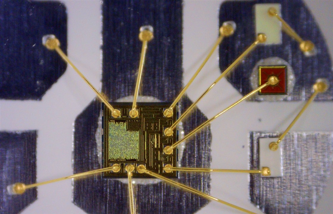
- SMD LED Soldering at Home
The fact this design challenge required SMD soldering and PCB design may have turned off some users. In this posting, I show how I solder the 5050-size LEDs using the provided Adafruit break-outs, accompanied by a leisurely video showing the process. A total of twenty LEDs were soldered by the end.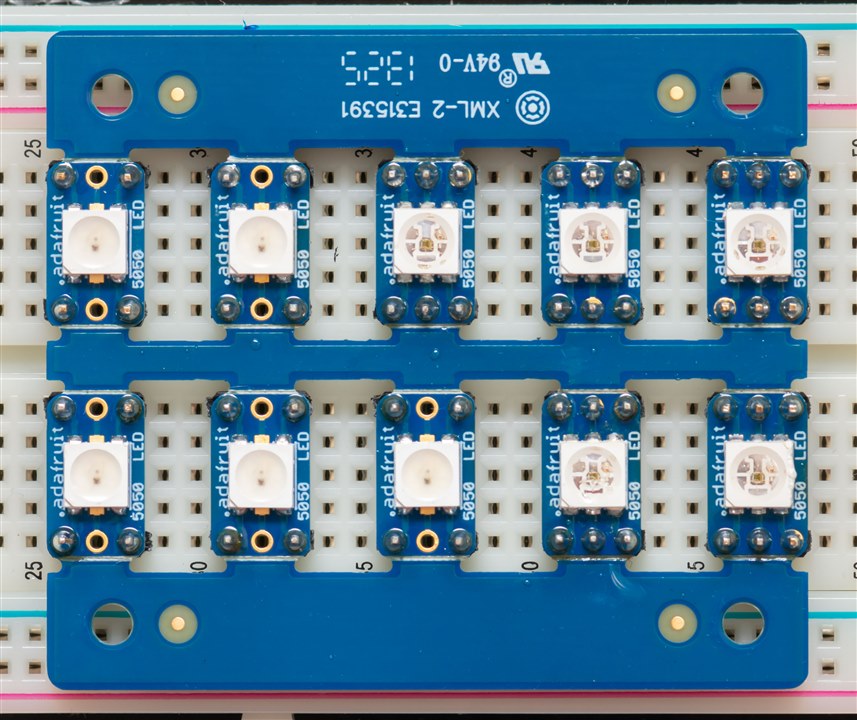
- Lighting Up My Life (a little bit)
In this post, I get the WL-ICLEDs soldered in the previous post to light up, using the provided Arduino Zero and the FastLED library. It was a marathon breadboarding effort, spanning two breadboards! I perform some extra experiments looking at wavelength spectra, PWM frequency and current consumption. I also test the LEDs on the RP2040 platform – rather surprisingly, it all just worked and it seemed one can get away without a level shifter (albeit, being a bit borderline in some cases).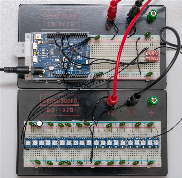
- Designing a PCB & 3D Printable Mechanicals
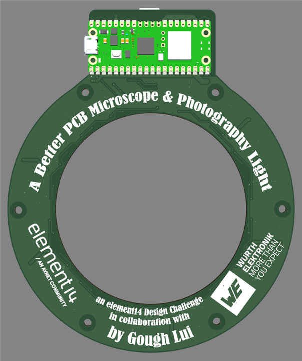
It was time to get serious and put my money where my mouth is – it was time to draw up a design and get the PCBs manufactured and shipped to me. I design both a ring light, featuring 3 x 18 LED strings of different types, and an Arduino shield featuring 25 LEDs of another. I also design the 3D printable carrier for the device – this post containing various design files.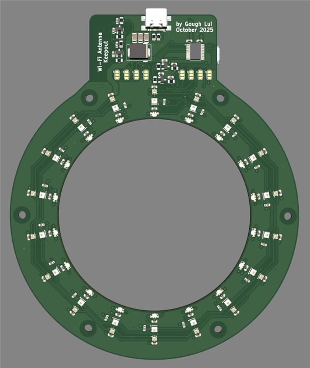
- PCBs Arrive & The Ultimate Skills Test
I was afraid that the PCBs wouldn’t arrive in time, but everything did with ample time to spare especially as the contest was extended. This time, the LEDs were much smaller – so I go through a key list of “secrets to success” which I use. In the end, construction was successful and designed some additional 3D prints to improve the diffusion and beam characteristics of the light output. There were no casualties or lost LEDs, and the FastLED demo reel worked just fine.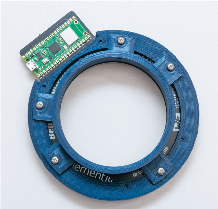
- Software Complete & System Demo
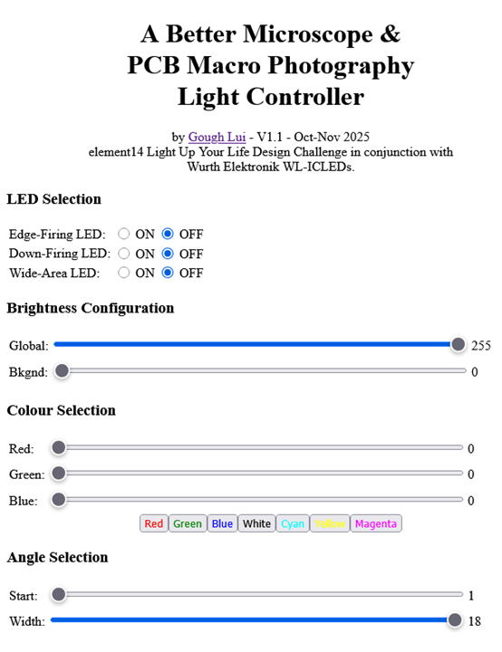
Being able to run the demo reel was not the purpose of the project, so I wrote my own software to complete the project. This first version is a webpage served from the Raspberry Pi Pico W that allows for the light to be controlled using the web browser on a phone, tablet or computer. This worked fairly well with a limited refresh rate (~10Hz) although there were issues with the 48-bit WL-ICLEDs and FastLED’s WS2816 type. The Arduino shield was able to display text using the Adafruit NeoMatrix library, but with only 5 pixels height, legibility was going to be limited. Code and a video demonstration are included.
Where we left off in Part 6, the system was working but not quite bug-free and there were a few good suggestions from the members, so I embarked on an improvement program.
Close … But Not Close Enough!
With just two weeks remaining to submission (and contracting the flu a second time this design challenge), I had to work quickly to make it all work the way I wanted it to.
The 48-bit LED Problem
In the line-up of WL-ICLEDs, there is only one 48-bit type (1312121320437), so I didn’t have much experience with it. The protocol is similar to WS2812B for timings, but transactions required twice the amount of data per pixel. Of the 16-bits, four bits were used for current scaling and 12-bits for PWM data. Now, I thought this was corresponding to the WS2816 type selection in the FastLED library code, but when ramping up and down, it’s not smooth – instead it “flashes” up and down in brightness … coincidentally, sixteen times throughout the full range.
As FastLED is optimised for 8-bit pixel data, it’s not the best library to use if you want to make use of the full resolution. But for my non-demanding application, it would be (theoretically) fine.
One easy way out was to ditch four bits and use the low four bits only. Unfortunately, now you have a 12-bit pixel … which is worse than the 24-bit pixels. But I did confirm that doing this does get rid of the strobing as it doesn’t “cross” over the higher four bits when scaled up to 16-bits. The cause was simply that FastLED considers the pixels’ 16-bits to be “all data” while in reality, you can think of the first four bits more as a “multiplier” and the last 12-bits as data.
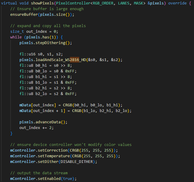
I went tracing through the library. The showPixels function for the WS2816 type shows how it manipulates eight bit values into an upper and lower, making them twice as long, but also needing to disable certain library corrections so they don’t modify the upper and lower bytes.
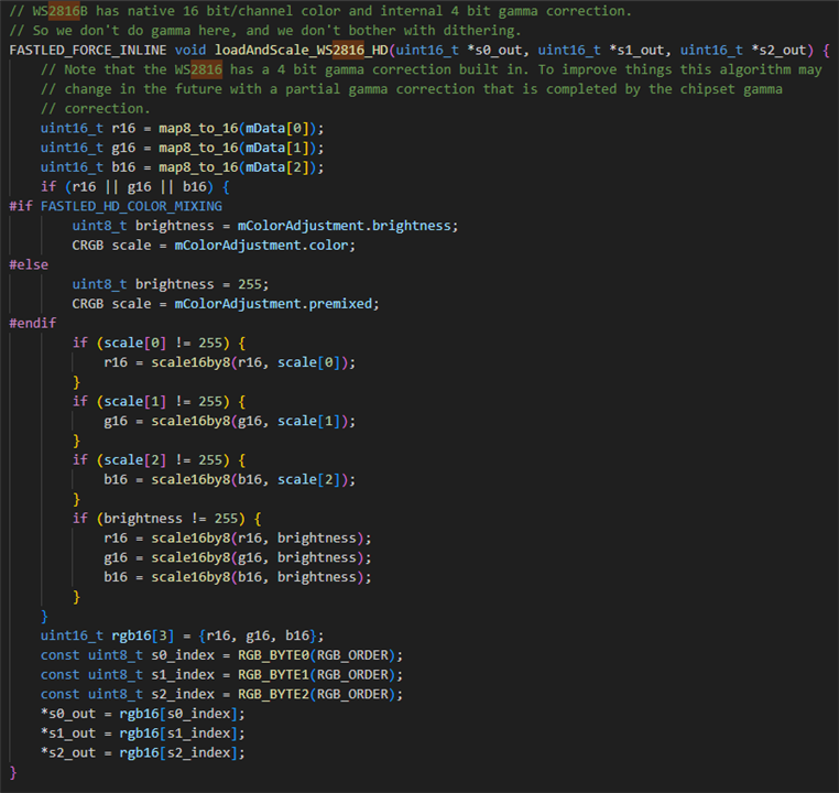
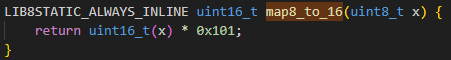
The secret seems to be in the loadAndScale_WS2816_HD function. I don’t understand it all – it mainly deals with corrections and whatnot, but it does type conversions with map8_to_16 and scale16by8.
From what I can see, they are naïve mathematical functions. But it’s not appropriate for this case – so I decided to simply replace the loadAndScale_WS2816_HD function with my own version that uses the bottom 12-bits by shifting in the 8-bit value and leaving the four LSB empty. Then, I take the upper four bits and set them to a fixed value – all ones for the maximum current. But I also need to take into account the global brightness value (as I’m using that in this sketch) which results in this function:
    FASTLED_FORCE_INLINE void loadAndScale_WS2816_HD(uint16_t *s0_out, uint16_t *s1_out, uint16_t *s2_out) {
        // GOUGH'S VERSION - DO NOT USE CURRENT SCALING BITS, FIX TO MAX
        uint16_t r16 = mData[0]<<4;
        uint16_t g16 = mData[1]<<4;
        uint16_t b16 = mData[2]<<4;
        uint8_t brightness = mColorAdjustment.brightness;
        if (brightness != 255) {
                r16 = scale16by8(r16, brightness);
                g16 = scale16by8(g16, brightness);
                b16 = scale16by8(b16, brightness);
        }
        r16 = r16 | 0xF000;
        g16 = g16 | 0xF000;
        b16 = b16 | 0xF000;
        uint16_t rgb16[3] = {r16, g16, b16};
        const uint8_t s0_index = RGB_BYTE0(RGB_ORDER);
        const uint8_t s1_index = RGB_BYTE1(RGB_ORDER);
        const uint8_t s2_index = RGB_BYTE2(RGB_ORDER);
        *s0_out = rgb16[s0_index];
        *s1_out = rgb16[s1_index];
        *s2_out = rgb16[s2_index];
    }
It's not going to work with all of FastLED’s features, but it does work for the features I need and the flickering is now gone!
Making Better Use of the RP2040
One thing I noticed about the last version of the software was that every browser request took some time to process and update on the LEDs, but in that time, another update could end up queueing up at the controller causing things to lag. As a result, I put in a JavaScript throttle to reduce the rate at which requests were being made. While this was successful at avoiding overload, it wasn’t as smooth as I would have liked, being about 10fps.
To improve this, I remembered that the Raspberry Pi RP2040 chip actually has two cores, so instead of having a single loop function, I can have two. Now the main core handles the web requests, while the second core writes to the LEDs. To prevent “sheared” writes, I implemented a set of flags which either cause the web request to wait for the write to LED to complete, or for the next LED write to be skipped while a web request was being processed. This way, I could update at a much nicer 30fps or so, making it feel almost silky smooth.
The updated code is provided in the “The Final Final Result” section.
Filling In the Shadows
The forum member beacon_dave made an excellent suggestion – to have the other LEDs which would ordinarily be off, be lit at a ratio to fill in shadows. Rather than implement a strict ratio – I decided to add two additional sliders to the interface – a global brightness slider and a background brightness slider. In theory, I could write a JavaScript function to implement the ratio, but I felt that was unnecessary as this would be more flexible.
The updated code is provided in the “The Final Final Result” section.
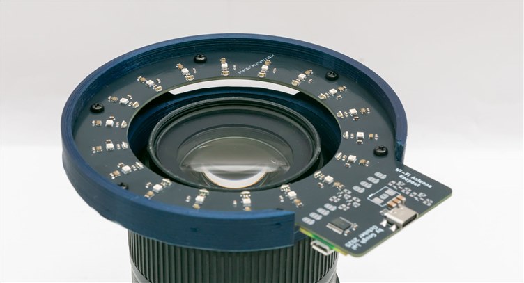
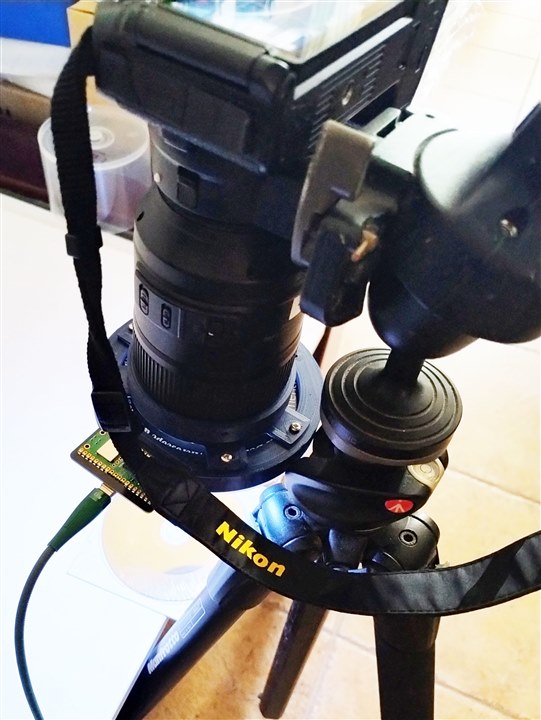
Fitting to a Microscope
From the outset of the project, I wanted the light to fit both my Nikkor 105mm macro lens and my microscope. The lens would set the minimum size of the inner diameter of the ring, while the microscope would set the maximum diameter of the ring (as it would otherwise collide with the stand). There wasn’t much wriggle room there, but I figured it would be possible.
While I did have screw holes for threading in M3 screws to cinch down onto the tube of the digital microscope, I didn’t count on the fact that the longest screws I had on hand simply weren’t long enough to make it fit.
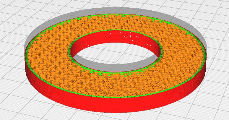
To fix this, I had to design a simple “donut” adapter. This was basically a solid 3D printed “ring” which could be put into the ring light and would friction-fit onto the end of the microscope. Alternatively, I could have made it two “half” donuts so the screws can “clamp” it together.
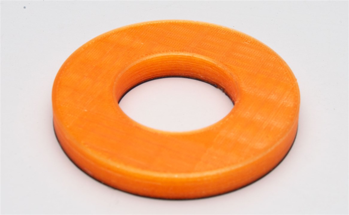
I managed to print it in translucent orange PLA that I had left over – not as nice as the metallic blue stuff, but I was in a hurry and I didn’t know if it will work so I used what was lying around.
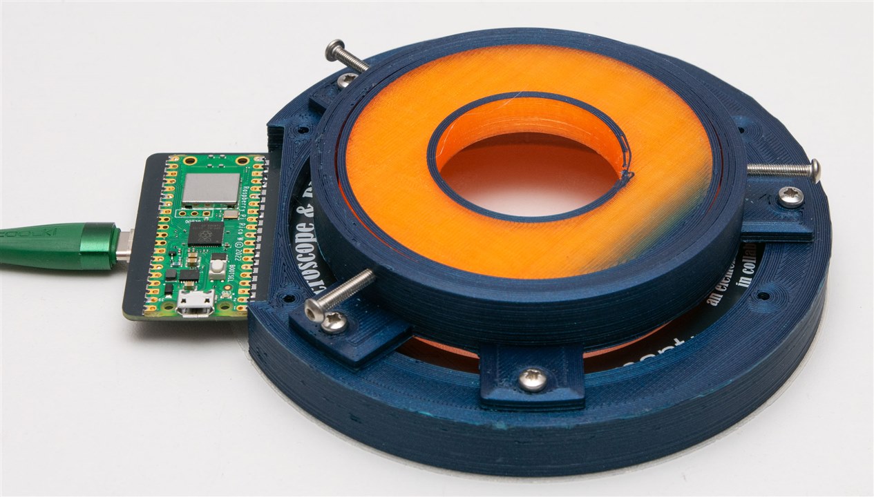
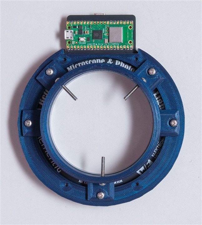
It fits inside the ring light holder as such … and is kept captive by the screws.
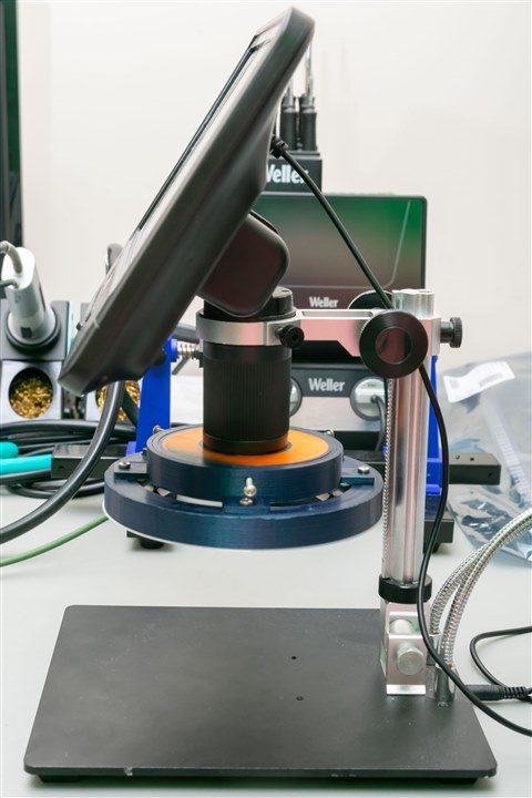
No surprises – it’s a tight fit but it’s on the microscope! All that design work pays off! The printable STL design is provided in the “The Final Final Result” section.
Co-ordinating Colour?
One thing I did notice was a minor LED-to-LED colour variation. This seemed particularly noticeable for the 48-bit type (1312121320437), but because of the way the LEDs were soldered, I can’t discount the possibility of overheating causing the issues. Nor could I discount the possibility of the LEDs themselves operating hot which can cause drifts in output.
To test this, I tried running the ring light at full brightness white with all LEDs turned on for about half-an-hour. While it was running, I realised the diffuser and baffles acted as blankets, keeping the heat in, while the small slits on the back and the clearance around the edge-firing LEDs were the only way that heat would get out. I kept as much of the copper plane on the PCB to aid heat dissipation, but it was still only a two-layer board with 1oz copper.
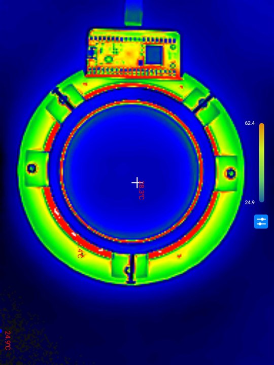
From the back, we were already seeing a peak of 62.4 degrees C from the back side of the PCB.
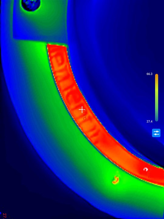
Looking through the slit, it was more like 66.3 degrees C. This is “toasty” but perhaps not lethal to the LEDs (at least, not immediately). It does remind us that we need to be mindful of the total heat dissipation and junction temperature, especially in large arrays. But as long as we don’t turn everything on, things should be cooler.
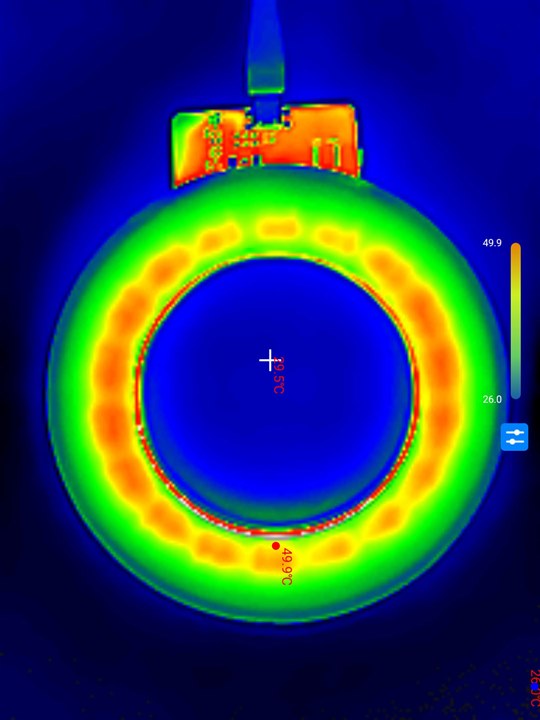
From the front, with the diffuser on, there was no clear pattern as to any particularly hot spots, which is good. But one needs to be a bit careful too, as the temperature is pretty much at the glass transition temperature of PLA.
Perhaps a metal-core circuit board for high-density LED deployments is advisable, backing onto a heatsink for better thermal dissipation.
But then there is also the issue of batch-to-batch LED variation. I spotted a colour calculator on Würth Elektronik’s site, so I thought it’d be worth a mention. You don’t have to have a RedExpert account to use it but you do get more features (ability to save, recall logs) if you do.
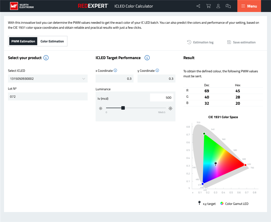

The two main modes are PWM Estimation and Colour Estimation.
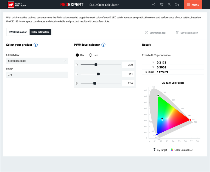
Changing the batch does change the result, so it is likely based on real production data. However, it is only available for one type of LED at this time.
The Final Final Result
After all of the fixes, it’s time to show the final result.
Demonstration
The final system can be seen in action in the video above along with some examples of what changing angular illumination looks like under a macro lens and microscope. In all, I would consider this a success and it worked quite a bit better than I expected even with highly reflective items such as optical discs. There is still room for further improvement, but I feel it’s a good result for a first attempt.
Bill of Materials & Design Resources
The PCB electronics bill of materials are as follows:
- 64 x 100n 0603 capacitor
- 3 x 100u 1206 capacitor
- 18 x Würth Elektronik 1313210530000 WL-ICLED
- 18 x Würth Elektronik 1312121320437 WL-ICLED
- 18 x Würth Elektronik 1311610030140 WL-ICLED
- 1 x GCT USB4110-GF-A USB-C Connector
- 2 x 5k1 0805 resistor
- 1 x Raspberry Pi Pico W
- 1 x Texas Instruments TXS0108EPW level shifter IC
The gerbers for the PCB can be downloaded here: LUYL-Gough-Lui-uscope-light.zip
All 3D Printing STL designs can be downloaded here: LUYL-Gough-Lui-3D-Printing.zip
The code that runs the ring light is as follows:
// A Better Microscope &<br>PCB Macro Photography Light V1.1
// element14 Light-Up-Your-Life Design Challenge
// by Gough Lui - October-November 2025

// Build Requires:
// - PCB, Wurth Elektronik WL-ICLEDs, Raspberry Pi Pico W, 3D Prints
//   (see element14 Community Design Challenge Post)
// - Arduino IDE (https://www.arduino.cc/en/software/)
// - Earle Philhower III Arduino Pico Core (https://github.com/earlephilhower/arduino-pico)
// - WiFiWebServer Library (https://github.com/khoih-prog/WiFiWebServer)
// - FastLED Library (https://github.com/FastLED/FastLED)

#include <WiFi.h>
#include <WiFiClient.h>
#include <WebServer.h>
#include <FastLED.h>

#define FRAMES_PER_SECOND  240

// FIRST STRING - EDGE FIRING
#define DATA_PIN    11 // Raspberry Pi Pico
#define LED_TYPE    WS2812B
#define COLOR_ORDER GRB
#define NUM_LEDS    18
CRGB leds[NUM_LEDS];

// SECOND STRING  - DOWN FIRING
#define DATA_PIN2    10 // Raspberry Pi Pico
#define LED_TYPE2    WS2816
#define COLOR_ORDER2 RGB
#define NUM_LEDS2    18
CRGB leds2[NUM_LEDS2];

// THIRD STRING - WIDE AREA DIFFUSE
#define DATA_PIN3    3 // Raspberry Pi Pico
#define CLK_PIN3     2
#define LED_TYPE3    APA102
#define COLOR_ORDER3 GBR
#define NUM_LEDS3    18
CRGB leds3[NUM_LEDS3];

// LED Parameters
int led_edge;
int led_down;
int led_wide;
int led_rvalue;
int led_gvalue;
int led_bvalue;
int led_ivalue;
int led_wvalue;
int led_gbright=255;
int led_bgbright;
int led_updating=0;
int led_drawing=0;

// Wi-Fi Parameters
char ssid[] = "YOUR_SSID_HERE";
char pass[] = "YOUR_PASSPHRASE_HERE";
int status = WL_IDLE_STATUS;

WebServer server(80);

const String postForms = "<!DOCTYPE html><html>\
<head>\
<meta name=\"viewport\" content=\"width=device-width, initial-scale=1.0\">\
<title>A Better Microscope & PCB Macro Photography Light Controller</title>\
<style>\
body {\
max-width: 640px\;\
}\
input[type=\"range\"] {\
width: 500px;\
}\
</style>\
</head>\
<body>\
<script>\
function throttle(callback, limit) {\
let lastCall=0;\
return function (...args) {\
const now = Date.now();\
if (now-lastCall>=limit) {\
lastCall=now;\
callback.apply(this,args);\
}\
};\
}\
function formfunc () {\
var form = new FormData(document.getElementById(\"paramform\"))\;\
fetch(\"post/\", {\
method: \"POST\",\
body: form\
})\
.then(res => res.text())\
.then(txt => {\
console.log(txt)\;\
})\
.catch(e => console.error(e))\;\
return false;\
}\
</script>\
<center><h1>A Better Microscope &<br>PCB Macro Photography<br>Light Controller</h1>\
by <a href=\"https://goughlui.com/\">Gough Lui</a> - V1.1 - Oct-Nov 2025<br>\
element14 Light Up Your Life Design Challenge in conjunction with<br>Wurth Elektronik WL-ICLEDs.</center>\
<form id=\"paramform\" method=\"post\" enctype=\"application/x-www-form-urlencoded\" action=\"#\" onsubmit=\"return formfunc()\;\">\
<h3>LED Selection</h3>\
<table><tr><td>Edge-Firing LED:</td><td><input type=\"radio\" id=\"led_edge\" name=\"led_edge\" value=\"1\">\
<label for=\"led_edge\"> ON</label> <input type=\"radio\" id=\"led_edge2\" name=\"led_edge\" value=\"0\" checked>\
<label for=\"led_edge2\"> OFF</label></td></tr>\
<tr><td>Down-Firing LED:</td><td><input type=\"radio\" id=\"led_down\" name=\"led_down\" value=\"1\">\
<label for=\"led_down\"> ON</label> <input type=\"radio\" id=\"led_down2\" name=\"led_down\" value=\"0\" checked>\
<label for=\"led_down2\"> OFF</label></td></tr>\
<tr><td>Wide-Area LED:</td><td><input type=\"radio\" id=\"led_wide\" name=\"led_wide\" value=\"1\">\
<label for=\"led_wide\"> ON</label> <input type=\"radio\" id=\"led_wide2\" name=\"led_wide\" value=\"0\" checked>\
<label for=\"led_wide2\"> OFF</label></td></tr></table>\
<h3>Brightness Configuration</h3>\
<table><tr><td>Global:</td><td><input type=\"range\" id=\"led_gbright\" name=\"led_gbright\" min=\"0\" max=\"255\" value=\"255\"></td><td><span id=\"gbsliderValue\"></span></td></tr>\
<script>\
const slider7 = document.getElementById(\"led_gbright\");\
const output7 = document.getElementById(\"gbsliderValue\");\
output7.innerHTML = slider7.value\;\
slider7.addEventListener(\"input\", function() {\
  output7.innerHTML = this.value\;\
})\;\
</script>\
<tr><td>Bkgnd:</td><td><input type=\"range\" id=\"led_bgbright\" name=\"led_bgbright\" min=\"0\" max=\"255\" value=\"0\"></td><td><span id=\"bgsliderValue\"></span></td></tr></table>\
<script>\
const slider8 = document.getElementById(\"led_bgbright\");\
const output8 = document.getElementById(\"bgsliderValue\");\
output8.innerHTML = slider8.value\;\
slider8.addEventListener(\"input\", function() {\
  output8.innerHTML = this.value\;\
})\;\
</script>\
<h3>Colour Selection</h3>\
<table><tr><td>Red:</td><td><input type=\"range\" id=\"led_rvalue\" name=\"led_rvalue\" min=\"0\" max=\"255\" value=\"0\"></td><td><span id=\"rsliderValue\"></span></td></tr>\
<script>\
const slider1 = document.getElementById(\"led_rvalue\");\
const output1 = document.getElementById(\"rsliderValue\");\
output1.innerHTML = slider1.value\;\
slider1.addEventListener(\"input\", function() {\
  output1.innerHTML = this.value\;\
})\;\
</script>\
<tr><td>Green:</td><td><input type=\"range\" id=\"led_gvalue\" name=\"led_gvalue\" min=\"0\" max=\"255\" value=\"0\"></td><td><span id=\"gsliderValue\"></span></td></tr>\
<script>\
const slider2 = document.getElementById(\"led_gvalue\");\
const output2 = document.getElementById(\"gsliderValue\");\
output2.innerHTML = slider2.value\;\
slider2.addEventListener(\"input\", function() {\
  output2.innerHTML = this.value\;\
})\;\
</script>\
<tr><td>Blue:</td><td><input type=\"range\" id=\"led_bvalue\" name=\"led_bvalue\" min=\"0\" max=\"255\" value=\"0\"></td><td><span id=\"bsliderValue\"></span></td></tr></table>\
<script>\
const slider3 = document.getElementById(\"led_bvalue\");\
const output3 = document.getElementById(\"bsliderValue\");\
output3.innerHTML = slider3.value\;\
slider3.addEventListener(\"input\", function() {\
  output3.innerHTML = this.value\;\
})\;\
</script>\
<center><button onclick=\"setColour('Red')\" style=\"color: red;\">Red</button>\
<button onclick=\"setColour('Green')\" style=\"color: green;\">Green</button>\
<button onclick=\"setColour('Blue')\" style=\"color: blue;\">Blue</button>\
<button onclick=\"setColour('White')\">White</button>\
<button onclick=\"setColour('Cyan')\" style=\"color: cyan;\">Cyan</button>\
<button onclick=\"setColour('Yellow')\" style=\"color: yellow;\">Yellow</button>\
<button onclick=\"setColour('Magenta')\" style=\"color: magenta;\">Magenta</button></center>\
<script>\
function setColour(rcolour) {\
const slider1 = document.getElementById(\"led_rvalue\");\
const output1 = document.getElementById(\"rsliderValue\");\
const slider2 = document.getElementById(\"led_gvalue\");\
const output2 = document.getElementById(\"gsliderValue\");\
const slider3 = document.getElementById(\"led_bvalue\");\
const output3 = document.getElementById(\"bsliderValue\");\
if (rcolour == \"Red\") {\
slider1.value = 255;\
slider2.value = 0;\
slider3.value = 0;\
} else if (rcolour == \"Green\") {\
slider1.value = 0;\
slider2.value = 255;\
slider3.value = 0;\
} else if (rcolour == \"Blue\") {\
slider1.value = 0;\
slider2.value = 0;\
slider3.value = 255;\
} else if (rcolour == \"White\") {\
slider1.value = 255;\
slider2.value = 255;\
slider3.value = 255;\
} else if (rcolour == \"Cyan\") {\
slider1.value = 0;\
slider2.value = 255;\
slider3.value = 255;\
} else if (rcolour == \"Yellow\") {\
slider1.value = 255;\
slider2.value = 255;\
slider3.value = 0;\
} else if (rcolour == \"Magenta\") {\
slider1.value = 255;\
slider2.value = 0;\
slider3.value = 255;\
};\
output1.innerHTML = slider1.value\;\
output2.innerHTML = slider2.value\;\
output3.innerHTML = slider3.value\;\
}\
</script>\
<h3>Angle Selection</h3>\
<table><tr><td>Start:</td><td><input type=\"range\" id=\"led_ivalue\" name=\"led_ivalue\" min=\"1\" max=\"18\" value=\"1\"></td><td><span id=\"isliderValue\"></span></td></tr>\
<script>\
const slider4 = document.getElementById(\"led_ivalue\");\
const output4 = document.getElementById(\"isliderValue\");\
output4.innerHTML = slider4.value\;\
slider4.addEventListener(\"input\", function() {\
  output4.innerHTML = this.value\;\
})\;\
</script>\
<tr><td>Width:</td><td><input type=\"range\" id=\"led_wvalue\" name=\"led_wvalue\" min=\"1\" max=\"18\" value=\"18\"></td><td><span id=\"wsliderValue\"></span></td></tr></table>\
<script>\
const slider5 = document.getElementById(\"led_wvalue\");\
const output5 = document.getElementById(\"wsliderValue\");\
output5.innerHTML = slider5.value\;\
slider5.addEventListener(\"input\", function() {\
  output5.innerHTML = this.value\;\
})\;\
</script>\
<br>\
<!--<center><input type=\"submit\" value=\"Submit\"></center>-->\
</form>\
<script>\
document.addEventListener(\"DOMContentLoaded\", function() {\
const i1 = document.getElementById(\"led_edge\");\
const i2 = document.getElementById(\"led_down\");\
const i3 = document.getElementById(\"led_wide\");\
const i1b = document.getElementById(\"led_edge2\");\
const i2b = document.getElementById(\"led_down2\");\
const i3b = document.getElementById(\"led_wide2\");\
const i4 = document.getElementById(\"led_rvalue\");\
const i5 = document.getElementById(\"led_gvalue\");\
const i6 = document.getElementById(\"led_bvalue\");\
const i7 = document.getElementById(\"led_ivalue\");\
const i8 = document.getElementById(\"led_wvalue\");\
const i9 = document.getElementById(\"led_gbright\");\
const i10 = document.getElementById(\"led_bgbright\");\
i4.addEventListener(\"input\", throttle(formfunc,40));\
i5.addEventListener(\"input\", throttle(formfunc,40));\
i6.addEventListener(\"input\", throttle(formfunc,40));\
i7.addEventListener(\"input\", throttle(formfunc,40));\
i8.addEventListener(\"input\", throttle(formfunc,40));\
i9.addEventListener(\"input\", throttle(formfunc,40));\
i10.addEventListener(\"input\", throttle(formfunc,40));\
i1.addEventListener(\"change\", formfunc);\
i2.addEventListener(\"change\", formfunc);\
i3.addEventListener(\"change\", formfunc);\
i1b.addEventListener(\"change\", formfunc);\
i2b.addEventListener(\"change\", formfunc);\
i3b.addEventListener(\"change\", formfunc);\
i4.addEventListener(\"change\", formfunc);\
i5.addEventListener(\"change\", formfunc);\
i6.addEventListener(\"change\", formfunc);\
i7.addEventListener(\"change\", formfunc);\
i8.addEventListener(\"change\", formfunc);\
i9.addEventListener(\"change\", formfunc);\
i10.addEventListener(\"change\", formfunc);\
});\
</script>\
</body>\
</html>";

void handleRoot() {
  server.send(200, "text/html", postForms);
  //Serial.println("Root Request Handled!");
}

void handleForm() {
  if (server.method() != HTTP_POST) {
    server.send(405, "text/plain", "Method Not Allowed");
  } else {
    //String message = "POST form was:\n";
    //for (uint8_t i = 0; i < server.args(); i++) {
    //  message += " " + server.argName(i) + ": " + server.arg(i) + "\n";
    //}
    String message = "1";
    server.send(200, "text/plain", message);
    //Serial.println("Post Request Handled!");
    //Serial.println(message);
  }
  // Separate POST values into variables
  for (uint8_t i = 0; i < server.args(); i++) {
    if (server.argName(i) == "led_edge") {
      //Serial.println("Updated Parameter led_edge");
      led_edge = server.arg(i).toInt();
    } else if (server.argName(i) == "led_down") {
      //Serial.println("Updated Parameter led_down");
      led_down = server.arg(i).toInt();
    } else if (server.argName(i) == "led_wide") {
      //Serial.println("Updated Parameter led_wide");
      led_wide = server.arg(i).toInt();
    } else if (server.argName(i) == "led_rvalue") {
      //Serial.println("Updated Parameter led_rvalue");
      led_rvalue = server.arg(i).toInt();
    } else if (server.argName(i) == "led_gvalue") {
      //Serial.println("Updated Parameter led_gvalue");
      led_gvalue = server.arg(i).toInt();
    } else if (server.argName(i) == "led_bvalue") {
      //Serial.println("Updated Parameter led_bvalue");
      led_bvalue = server.arg(i).toInt();
    } else if (server.argName(i) == "led_ivalue") {
      //Serial.println("Updated Parameter led_ivalue");
      led_ivalue = server.arg(i).toInt();
    } else if (server.argName(i) == "led_wvalue") {
      //Serial.println("Updated Parameter led_wvalue");
      led_wvalue = server.arg(i).toInt();
    } else if (server.argName(i) == "led_gbright") {
      //Serial.println("Updated Parameter led_gbright");
      led_gbright = server.arg(i).toInt();
    } else if (server.argName(i) == "led_bgbright") {
      //Serial.println("Updated Parameter led_bgbright");
      led_bgbright = server.arg(i).toInt();
    }
  }
  // Edit the LED arrays
  while(led_drawing) {
  } // Hold while the last draw completes
  led_updating=1; // Lock out drawing
  FastLED.clear();
  if(led_edge) {
    fill_solid(leds,NUM_LEDS,CRGB(led_rvalue,led_gvalue,led_bvalue));
    fadeToBlackBy(leds,NUM_LEDS,(255-led_bgbright));
    for(int z=(led_ivalue-1);z<(led_ivalue+led_wvalue-1);z++) {
      leds[z%NUM_LEDS] = CRGB(led_rvalue,led_gvalue,led_bvalue);
    }
  }
  if(led_down) {
    fill_solid(leds2,NUM_LEDS2,CRGB(led_rvalue,led_gvalue,led_bvalue));
    fadeToBlackBy(leds2,NUM_LEDS2,(255-led_bgbright));
    for(int z=(led_ivalue-1);z<(led_ivalue+led_wvalue-1);z++) {
      leds2[z%NUM_LEDS2] = CRGB(led_rvalue,led_gvalue,led_bvalue);
    }
  }
  if(led_wide) {
    fill_solid(leds3,NUM_LEDS3,CRGB(led_rvalue,led_gvalue,led_bvalue));
    fadeToBlackBy(leds3,NUM_LEDS3,(255-led_bgbright));
    for(int z=(led_ivalue-1);z<(led_ivalue+led_wvalue-1);z++) {
      leds3[z%NUM_LEDS3] = CRGB(led_rvalue,led_gvalue,led_bvalue);
    }
  }
  led_updating=0;
}

void handleNotFound() {
  String message = "File Not Found\n\n";
  message += "URI: ";
  message += server.uri();
  message += "\nMethod: ";
  message += (server.method() == HTTP_GET) ? "GET" : "POST";
  message += "\nArguments: ";
  message += server.args();
  message += "\n";
  for (uint8_t i = 0; i < server.args(); i++) {
    message += " " + server.argName(i) + ": " + server.arg(i) + "\n";
  }
  server.send(404, "text/plain", message);
}

void setup() {
  Serial.begin(115200);
  FastLED.addLeds<LED_TYPE,DATA_PIN,COLOR_ORDER>(leds, NUM_LEDS);
  FastLED.addLeds<LED_TYPE2,DATA_PIN2,COLOR_ORDER2>(leds2, NUM_LEDS2);
  FastLED.addLeds<LED_TYPE3,DATA_PIN3,CLK_PIN3,COLOR_ORDER3>(leds3, NUM_LEDS3);
  FastLED.setBrightness(led_gbright);
  FastLED.clear();
  //while (!Serial) {
  //}
  Serial.println("A Better Microscope & PCB Macro Photography Light");
  Serial.println("by Gough Lui (goughlui.com) - Oct-Nov 2025 - V1.1");
  Serial.println("-------------------------------------------------");
  Serial.print("Attempting to connect ");
  while (status != WL_CONNECTED) {
    status = WiFi.begin(ssid, pass);
    Serial.print(".");
    delay(5000);
  }
  Serial.println(" OK!");

  // print the SSID of the network you're attached to:
  Serial.print("SSID: ");
  Serial.println(WiFi.SSID());
  // print the MAC address of the router you're attached to:
  byte bssid[6];
  WiFi.BSSID(bssid);
  Serial.print("BSSID: ");
  Serial.print(bssid[5], HEX);
  Serial.print(":");
  Serial.print(bssid[4], HEX);
  Serial.print(":");
  Serial.print(bssid[3], HEX);
  Serial.print(":");
  Serial.print(bssid[2], HEX);
  Serial.print(":");
  Serial.print(bssid[1], HEX);
  Serial.print(":");
  Serial.println(bssid[0], HEX);
  // print the received signal strength:
  long rssi = WiFi.RSSI();
  Serial.print("signal strength (RSSI):");
  Serial.println(rssi);

  // print your WiFi shield's IP address:
  IPAddress ip = WiFi.localIP();
  Serial.print("IP Address: ");
  Serial.println(ip);
  // print your MAC address:
  byte mac[6];
  WiFi.macAddress(mac);
  Serial.print("MAC address: ");
  Serial.print(mac[5], HEX);
  Serial.print(":");
  Serial.print(mac[4], HEX);
  Serial.print(":");
  Serial.print(mac[3], HEX);
  Serial.print(":");
  Serial.print(mac[2], HEX);
  Serial.print(":");
  Serial.print(mac[1], HEX);
  Serial.print(":");
  Serial.println(mac[0], HEX);

  server.on("/", handleRoot);
  server.on("/post/", handleForm);
  server.onNotFound(handleNotFound);

  server.begin();
  Serial.println("HTTP server started!");
}

void loop() { // First core will handle HTTP requests only
  server.handleClient();
}

void setup1() {
  delay(500); // Let the first core set-up important structures
}

void loop1() {
  if(!led_updating) { // Avoid sheared update
    led_drawing=1;
    FastLED.setBrightness(led_gbright);
    FastLED.show(); // Dedicate the second core to updating outputs
    led_drawing=0;
  }
  FastLED.delay(1000/FRAMES_PER_SECOND);
}
Future Work and Improvements
While the design looks and works much better than I would have originally imagined, it still doesn’t quite satisfy for a few interesting reasons:
- RGB LEDs are probably not the best choice for photographic applications – perhaps if an RGBW LED or just a high CRI neutral-white LED with such intelligence were available, it would be a better choice. Part of the reason is that RGB LEDs can produce a very odd looking white with colour casts that can confuse cameras automatic white balance. I could tune the corrections for the LED to try and get it more in-line with a particular colour temperature, but the CRI will always be somewhat lacking and the differences in LED-to-LED colour manifests itself as different image colours as the light is rotated around.
- While the device allows me to rotate the light around the horizontal plane, it doesn’t do anything for the vertical. I could tilt the camera to achieve this with the macro lens, but this affects the focal plane too – while a microscope is stubbornly fixed vertically. Perhaps a bowl-shaped light would be better, with successive rows affecting the vertical angle. This would probably require the use of flexible PCBs adhered to a “form” of some sort. The angular resolution at 18 LEDs isn’t quite as fine as I would have liked, but given the optics and beam angle of the LEDs, the use of baffles was necessary to achieve the separation we already have – perhaps it’s just too much to ask short of having a “flexible colour OLED display” acting as a light source.
- I should have paid more attention to the output of the different types of LEDs used. I wanted to try them in a practical setting, but doing so, it’s clear that the edge and wide LEDs have significantly less output than the down-firing LEDs, making them less useful. This is especially the case when a smaller illumination angle means less LEDs are lit, which reduces the amount of light on the object being photographed. If the LEDs were “super powerful” and heat dissipation could be managed, perhaps we can operate in a mode of constant brightness regardless of segments lit.
- In line with that, the down-firing LEDs definitely take the bulk of the current budget and with about 5W dissipated between them all, thermal management could probably have been better if I chose a more expensive MCPCB (metal core PCB) and mounted it onto something that would absorb heat (e.g. an aluminium heatsink). This would help ensure colour consistency and avoid lifetime loss due to operating at high temperatures.
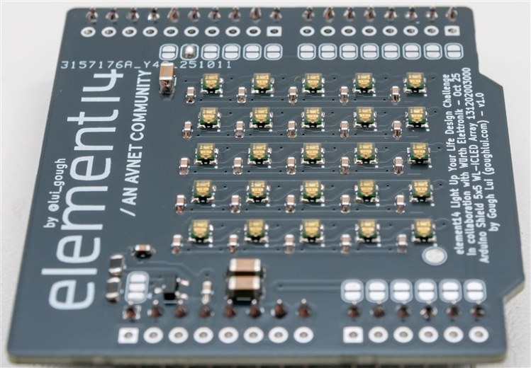
A Small Bonus Arduino Shield
As I have covered in a blog, I did create an Arduino shield as a bonus and this was demonstrated in Part 6. Just a reminder that it exists, thus I have been able to test every type of WL-ICLED there is!
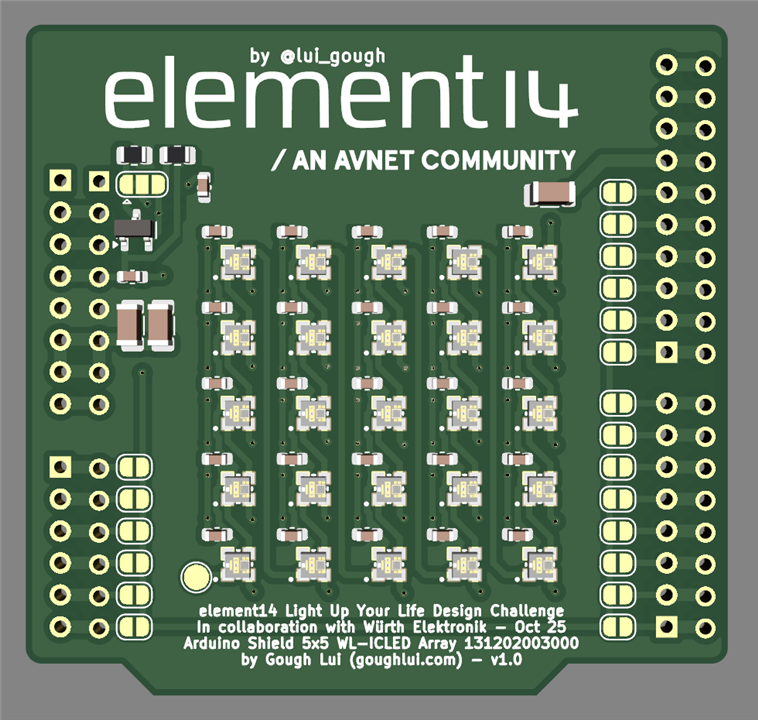
Bill of Materials & Design Resources
The PCB electronics bill of materials are as follows:
- 27 x 100n 0603 capacitors
- 3 x 100u 1206 capacitors
- 25 x Würth Elektronik 1312020030000 WL-ICLED
- 2 x 8-pin 2.54mm header pins
- 1 x 6-pin 2.54mm header pins
- 1 x 10-pin 2.54mm header pins
- 1 x BSS138 n-channel MOSFET
- 2 x 10k 0805 resistors
- 1 x Arduino Zero
The gerbers for the shield can be downloaded here: LUYL-Gough-Lui-arduino-shield.zip
The code to run this demo is as follows:
// element14 Light-Up-Your-Life Design Challenge
// by Gough Lui - October-November 2025
// Adapted from Adafruit_NeoMatrix example for single NeoPixel Shield
// for use with my Arduino Shield with Wurth Elektronik WL-ICLEDs (5x5)

// Build Requires:
// - PCB, Wurth Elektronik WL-ICLEDs, Arduino Zero
//   (see element14 Community Design Challenge Post)
// - Arduino IDE (https://www.arduino.cc/en/software/)
// - Adafruit NeoMatrix and all dependencies
//   (https://github.com/adafruit/Adafruit_NeoMatrix)

#include <Adafruit_GFX.h>
#include <Adafruit_NeoMatrix.h>
#include <Adafruit_NeoPixel.h>
#include <Fonts/TomThumb.h>

#define PIN 12

// MATRIX DECLARATION:
Adafruit_NeoMatrix matrix = Adafruit_NeoMatrix(5, 5, PIN,
  NEO_MATRIX_TOP     + NEO_MATRIX_LEFT +
  NEO_MATRIX_ROWS    + NEO_MATRIX_PROGRESSIVE,
  NEO_GRB            + NEO_KHZ800);

void setup() {
  matrix.begin();
  matrix.setTextWrap(false);
  matrix.setBrightness(12);
  matrix.setTextColor(matrix.Color(random(64,256),random(64,256),random(64,256)));
  matrix.setFont(&TomThumb);
}

int x    = matrix.width();
int pass = 0;

void loop() {
  matrix.fillScreen(0);
  matrix.setCursor(x, 5);
  matrix.print(F("element14 Light Up Your Life Design Challenge, in conjunction with \
Wurth Elektronik, featuring WL-ICLEDs. By Gough Lui - Oct/Nov 2025"));
  if(--x < -490) {
    x = matrix.width();
    matrix.setTextColor(matrix.Color(random(64,256),random(64,256),random(64,256)));
  }
  matrix.show();
  delay(67);
}
Future Work and Improvements
The shield itself was pretty straightforward. On the whole, I would have loved to have more LEDs to play with, thus a larger, more denser matrix could be formed which could have lent itself to more graphical uses. But considering what we were provided as challengers, I think it’s about as good as I could have expected – no LEDs lost or damaged!
Destruction: By Special Request
At the end of my Part 1 post, balajivan1995 asked if I had any spare LEDs, whether I could cut them apart for a cross-section. Well, I didn’t see much of a point in doing it initially, but now that my project has come to its end, I decided to get my sharpest Knipex side-cutters and give it a go.
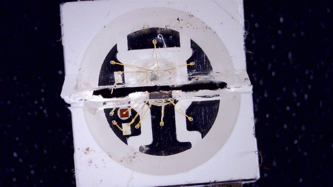
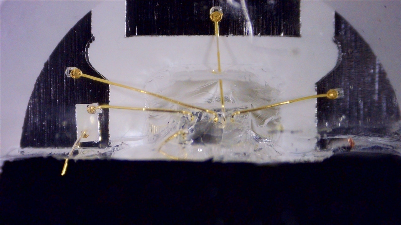
I tried for a cut right through the middle – unfortunately, this fractured the IC itself which, due to it being a silicon crystal, somewhat shattered in its brittle nature and pulled out of one half, leaving behind the wire bonds.
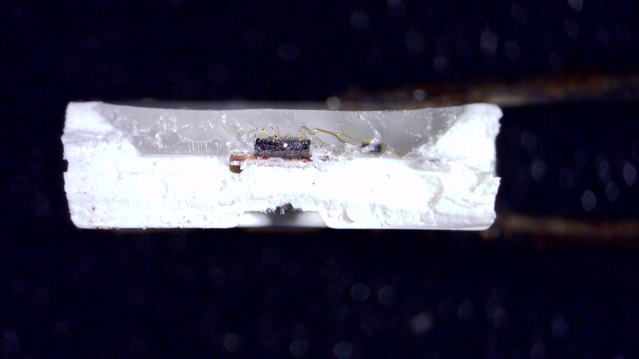
The half with the chip still in it, as viewed from the side. The thickness of the chip is evident as is the path of the wire bonds.
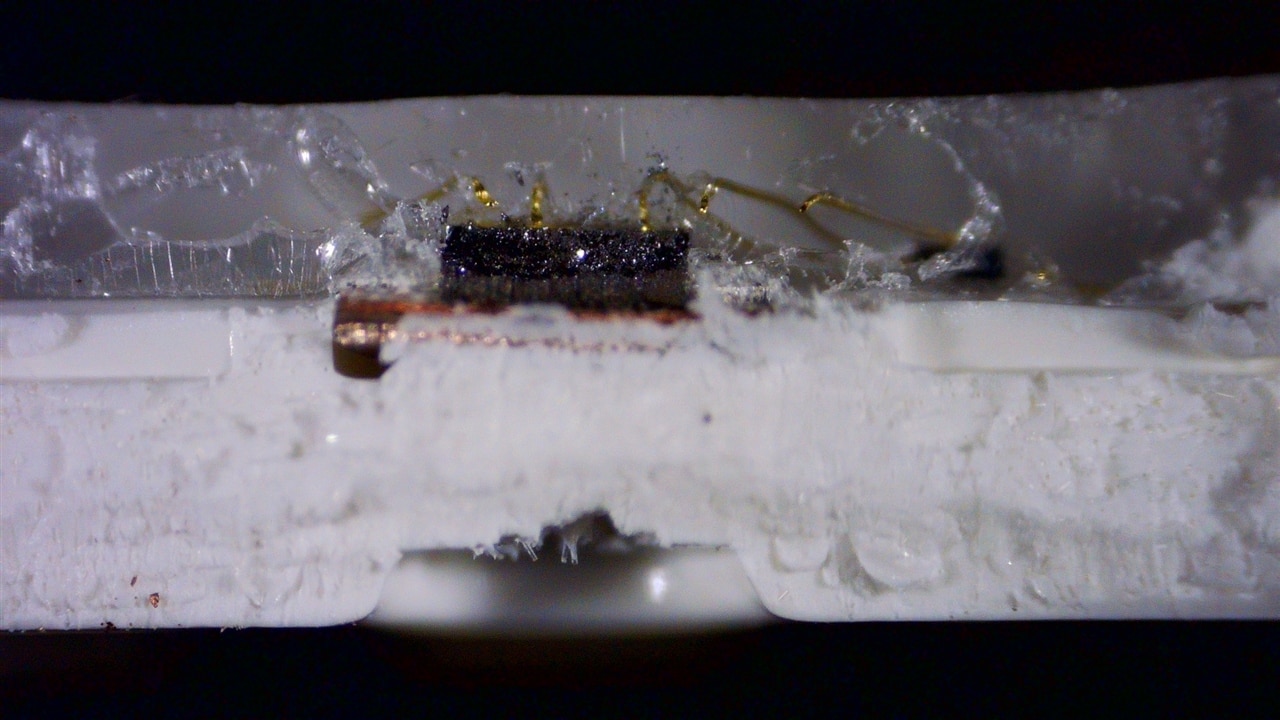
Looking closer, it seems that the base is perhaps tinned copper? An LED chip is seen in the background.
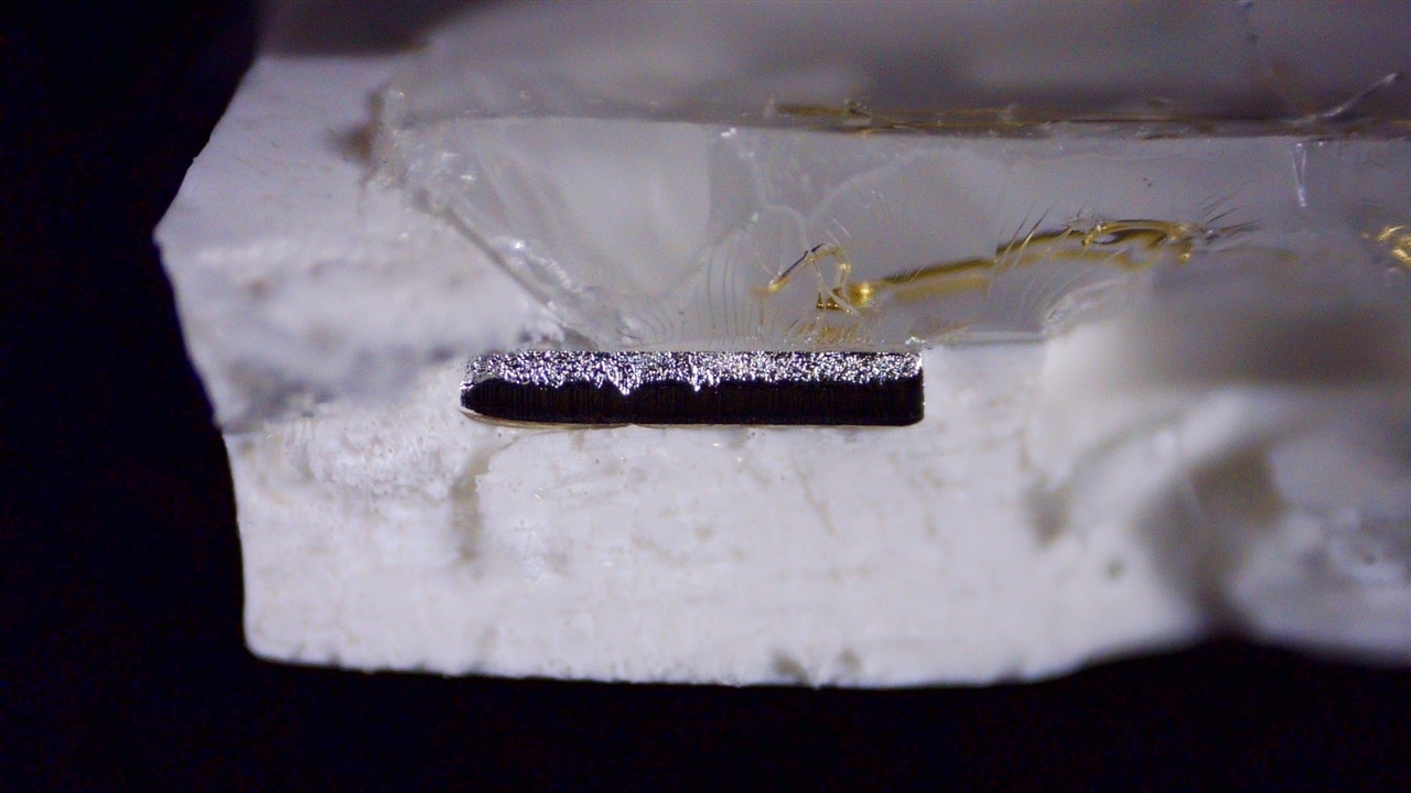
The cut went through one of the pads on the other side – a nice cut, but doesn’t show much detail.
That half of the chip practically disappeared – likely it fell out or was crumbled into dust.
I didn’t expect to see much, but I thought I should at least honour the request. My apologies to the LED gods (if there is one) for spoiling this particular device.
Conclusion
Thanks to element14 and Würth Elektronik for this opportunity to turn a concept I’ve had in my head for a while into reality. The contest really tested my capabilities, bringing together a whole range of skills from SMD soldering to breadboarding, schematic design, PCB layout and contract manufacture, writing JavaScript (meh) to C-code (yay), designing physical models for 3D printing to repairing my 3D printer (to actually make it happen), and taking photos, video and writing up my experiences to share with you all. I probably would have done better if I didn’t catch the flu twice and been so busy with other work at the same time – but even then, I gave it my all – motivated by a deadline and a wish to see it all come to fruition.
While the result isn’t perfect, it did result in a lot of learnings. I now know that the WL-ICLEDs are mostly compatible with known and popular types of RGB controller-based LEDs using common libraries such as FastLED or NeoPixel/NeoMatrix. The exception is the 48-bit type, but with a little editing, could be coaxed to work just fine as well. I now know that it’s possible to solder it at home provided you take some care, but it’s not easy for all especially the smaller varieties.
There’s a good chance that I’ll be using such LEDs in projects in the future as they make multiple RGB LEDs in a single product convenient and easy to implement by requiring very little in the way of I/O. The Würth Elektronik branding gives a bit more reassurance that such products are of quality and will be available in the longer term, their compatibility with common protocols means broader software compatibility too.
Top Comments
-

dougw
-
Cancel
-
Vote Up
+1
Vote Down
-
-
Sign in to reply
-
More
-
Cancel
Comment-

dougw
-
Cancel
-
Vote Up
+1
Vote Down
-
-
Sign in to reply
-
More
-
Cancel
Children