


Posts in this project
Pallet Tracker - 01 - Project description
Pallet Tracker - 02 - Development environment
Pallet Tracker - 03 - Application skeleton
Pallet Tracker - 04 - PSoC6 power modes and LPComp
Pallet Tracker - 05 - Evaluating power consumption
Pallet Tracker - 06 - Indoor localization
First of all, I need to properly setup the development environment
Installing the Modus Toolbox
One of the requirements for this challenge is the use of the new Eclipse-based IDE provided by Cypress for all their PSoC platforms: the Modus Toolbox. The alternative is the long-standing proprietary application PSoC Creator, which however supports only a subset of the PSoC6 MCUs.
ModusToolbox software includes configuration tools, low-level drivers, middleware libraries, and operating system support, as well as other packages that enable you to create MCU and wireless applications. It also includes an Eclipse IDE, which provides an integrated flow with all the ModusToolbox tools.
ModusToolbox supports stand-alone device and middleware configurators that are fully integrated into the Eclipse IDE. Use the configurators to set the configuration of different blocks in the device and generate code that can be used in firmware development. ModusToolbox supports all PSoC 6 MCU devices.
Here is a diagram with all the components included in the Modus Toolbox

Libraries and enablement software are available at the GitHub site
Modus Toolbox can be downloaded from this link
Setup process completes with no hassle.. However, after installation, I have been warned that a system variable (CY_TOOLS_PATH) was not set. In any case, I tried to build an example application and I got this error

So I simply opened Control Panel -> System -> Advanced settings
Then I clicked "Environment Variables..."
Then "New..", and created a new system variable
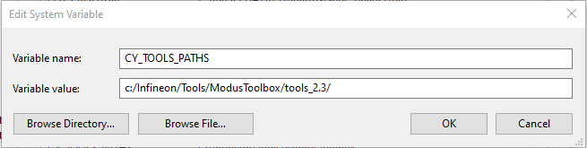
With this change, the example applications compiles successfully
The Hello_World application
Let's try to create and build a simple "Hello world" application that blinks a LED and prints some debug output on a serial console. Serial console output, as a matter of fact, is fundamental while developing an embedded system because it's your only window to the system internals and you can check application behavior in real-time, as application logic processes events
First of all, lets' create a new application application

This will launch the Project Creator, which is a tool that allows you to select the correct BSP (depending on the board you are using) and a template application to start developing your project from
The kit provided for this challenge is the CY8CKIT-062S2-43012, so let's select the corresponding entry in the list

Click "Next" to proceed and choose a template application. I chose the "Hello world" template, which, according to the description, "demonstrates simple UART communication by printing a "Hello World" message on a terminal and blinks an LED using a Timer resource using PSoC 6 MCU."

Click "Create" and a new Hello_World application will be created in your current workspace

An supplemental folder (mtb_shared) has been created to store the libraries shared source code. This code will be shared by all the project you are going to created, thus reducing the disk usage. However, the Library manager (another tool of the Modus Toolbos suite) allows you to create a copy of the libraries that is private to a certain project
The code for the Hello_World example is quite simple. First of all, it makes hardware initialization for the selected BSP
    /* Initialize the device and board peripherals */
    result = cybsp_init();
NOTE: I really appreciate the naming convention used throughout all the Cypress libraries. The function names gives you direct information about the context the function refers to. For example, the prefix "cybsp_" is a clue that the function is specific for the BSP
Then, the retarget_io library is initialized
    /* Initialize retarget-io to use the debug UART port */
    result = cy_retarget_io_init(CYBSP_DEBUG_UART_TX, CYBSP_DEBUG_UART_RX,
                                 CY_RETARGET_IO_BAUDRATE);
The Cypress retarget-io library implements low-level character I/O functions expected by the Arm and GNU C compilers. These functions are called from the printf() and scanf() functions that come from the STDIO C-language run-time library. The actual names of the functions depend on the compiler you are using, but the library is written so that the right implementations are enabled for you automatically. Here is some code to remind you how it works (this code works on all supported compilers).
As you may guess from the name, CYBSP_DEBUG_UART_TX and CYBSP_DEBUG_UART_RX are defined at BSP level. In particular, they are defined in
<workspace folder>\Hello_World\libs\TARGET_CY8CKIT-062S2-43012\COMPONENT_BSP_DESIGN_MODUS\GeneratedSource\cycfg_pins.s
#if defined (CY_USING_HAL)
#define CYBSP_DEBUG_UART_RX (P5_0)
#define CYBSP_D0 CYBSP_DEBUG_UART_RX
#endif //defined (CY_USING_HAL)
#if defined (CY_USING_HAL)
#define CYBSP_DEBUG_UART_TX (P5_1)
#define CYBSP_D1 CYBSP_DEBUG_UART_TX
#endif //defined (CY_USING_HAL)
Currently, I am not sure what the CY_USING_HAL is for, but I will try to understand this details later on during the development
CY_RETARGET_IO_BAUDRATE is defined in
<workspace folder>\mtb_shared\retarget-io\release-v1.2.0\cy_retarget_io.h
as
/** UART baud rate */
#define CY_RETARGET_IO_BAUDRATE             (115200)
After this initialization, you can send debug prints to a serial terminal be means of the standard C printf function
    printf("****************** "
           "PSoC 6 MCU: Hello World! Example "
           "****************** \r\n\n");
LED GPIO is initialized by calling the cyhal_gpio_init function
    /* Initialize the User LED */
    result = cyhal_gpio_init(CYBSP_USER_LED, CYHAL_GPIO_DIR_OUTPUT,
                             CYHAL_GPIO_DRIVE_STRONG, CYBSP_LED_STATE_OFF);
CYBSP_USER_LED is defined in
<workspace folder>\Hello_World\libs\TARGET_CY8CKIT-062S2-43012\COMPONENT_BSP_DESIGN_MODUS\GeneratedSource\cycfg_pins.s
as
#if defined (CY_USING_HAL)
#define CYBSP_LED8 (P1_5)
#define CYBSP_USER_LED1 CYBSP_LED8
#define CYBSP_USER_LED CYBSP_LED8
#endif //defined (CY_USING_HAL)
and driven by functions in the cyhal_gpio_ namespace
            /* Invert the USER LED state */
            cyhal_gpio_toggle(CYBSP_USER_LED);
In the "Quick panel", you can now build, deploy the application to the evaluation kit and debug the code

Click "Build Hello_World Application" to create the binary file, then click "Hello_World Debug (KitProg3_MiniProg4)" to start a debug session or "Hello_World Program (KitProg3_MiniProg4)" to run the application with no debugger
I opened a serial terminal, connected to the serial port corresponding to the PSoC6 board

and I got the following output

Very good! In the next post, I will start the real application and use the Library manager to include WiFi support and TCP/IP stack
Top Comments