


After having a first working version of the Command Center (PiIoT - DomPi 09: Presence Emulator) I have gone back to the Arduino remote nodes to develop the Garage node. I´m facing however some difficulties with the TFT and the RF24 board that I comment later in the post. As a high level summary of the Garage node, it shall provide three sets of information to the Command Center:
- Measurement of the distance to the car. This will support the park assistance feature and inform whether the car is in the garage
- Environmental data: temperature, humidity and luminosity. Similar to the other remote nodes.
- Movement detection. Similar to the other remote nodes.
A fundamental part of the garage node is the TFT. The TFT screen will assist us when parking the car by indicating the distance till the right parking position and also a color coded function (like a traffic light: green, yellow, red) to make it easier. At the heart of it I have an Arduino Mega 2560 - I´m moving out of the Arduino Nano used in the other nodes to have more flash memory and better fit with the 5" TFT screen.
Before going into the details, some quick links to the previous posts and the current project status.
Previous Posts
Project Status

Park Assistance
This feature consists of two new components to the DomPi: an ultrasonic sensor HC-SR04 and a 5" TFT LCD screen with the required shield to adapt it to the Arduino Mega. Let´s have a view at both components and its usage in the project.
 | 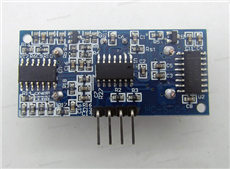 |  |  |
Picture sources: HC-SR04, TFT, shield.
Measuring the distance. The ultrasonic sensor
The HC-SR04 is a good price-quality solution and shall be more than enough for the usage it will have in the project. It can measure distances from 2cm up to 4-4,5 meters that covers all of my garage. The accuracy is less than 1cm and it is supposed to have good stability. On the downside, with the sensor I have at home I am not able to enjoy this performance and sometimes I am getting wrong distances even if the object is not moving that fast. The workaround will be to add some intelligence on the Command Center to avoid false measurements and false positives.
Operating principle. This is a 4-pin 5V module. To operate the sensor is quite straightforward. With the Arduino, you just need to send a high level pulse to the "Trig" pin of the sensor for at least 10us and look for a raising edge in the "Echo" pin of it. During this time, the sensor will send 8 pulses at 40Khz (ultrasound, that can´t be noticed by a person). The time passed between the raising edge and the falling edge of the "Echo" pin is the time it took to send and receive the ultrasonic signal. Since the speed of sound is around 343m/s you already can get the distance to the car: distance = time_passed x 343 / 2
Library. To implement the operating principle, I am leveraging the New Ping library (project home here). This library includes some improvements on how the timer and the interruptions are managed and also implements a cool function, ping_median, that returns the median of several measurements, discarding any out of range pings. The distance I am using comes from this function with the default of 5 measurements. I could increase the number of iterations of the median calculation and reduce the problems I face with inaccurate distance. But in principle, I will stick to this 5 iterations. The design reasoning is as follows: I will display this distance into the TFT so that when I am parking I can see the centimeters till the end. This will be updated every second, so even if I get 1 wrong measurement, that shouldn't be a problem and I should not hit the wall, hope so  . The second usage of the distance is for the "Car presence" feature that will be used in the Command Center, this feature indicates if the car is in the garage. This feature doesn't require a precise measurement either.
Displaying the distance. The TFT LCD screen
It´s good to have the distance, but it is better to inform the driver about it The solution is based on an big screen, a 5" LCD, and its adapter shield to connect it directly to the Arduino Mega. This shield, among other things, adapts the 5V of the Arduino pins to the 3.3V of the screen. The screen includes a touch screen function that I plan to use in the future to allow some direct interaction while I am in the garage.
Library. There is a very good and wide library written for the Arduino to implement many different TFT screens and touch screens, including the model I have. This is the UTFT library that can be found here. It took me a while to configure it and find the right pins, ensure the HW was well connected, etc, etc. The library comes with several examples and testers that helped me, like the UTFT_Demo_800x480.ino sketch. In my case, I am calling the constructor with this line, where the numbers reflect pins in the Mega connected to the TFT pins like cs, ce, etc:
UTFT myGLCD(TFT01_50,38,39,40,41);
To print something in the screen is quite simple with this function, just execute this line, where s is the String to print and Xpos, Ypos determine the position of the screen in pixels:
myGLCD.print(s, Xpos, Ypos)
If you plan to use the touch function, I recommend these two libraries: the UTouch and the UTFT_Buttons, both can be found in the same web.
For DomPi, besides printing the distance in centimeters in the middle of the screen, I´m also using a color coding depending on the distance:
- If the distance is bigger than 200cm, fill the screen with the green color
- if the distance is between 20cm and 200cm, fill in with yellow
- If the distance is smaller than 20cm, fill in with red
The code implementing this is here:
void displayDistance(uint16_t dist_cm_1a, bool showDist){
  //display distance in screen, if showDist=false clears screen
  if (showDist) {
    if (debug) Serial.print("Dist: ");
    if (debug) Serial.print(dist_cm_1a);
    if (debug) Serial.println (" cm");
    //myGLCD.lcdOn();
    if (dist_cm_1a > 200) myGLCD.fillScr(COLOR_VERDE);
    else if (dist_cm_1a > 20) myGLCD.fillScr(COLOR_AMARILLO);
    else myGLCD.fillScr(COLOR_ROJO);
    String s = String(dist_cm_1a);
    if (dist_cm_1a < 100) s = "0"+s;  //If 2 digits, adds 0s to the left
    if (dist_cm_1a <  10) s = "0"+s;
    myGLCD.print(s, Xpos, Ypos);  //If 1 digit, adds 0 to the left
  } else {
    //we just clear screen and turn it off
    myGLCD.clrScr();
    if (debug) Serial.println ("No activity. Screen to off");
    //myGLCD.lcdOff();
  }
}
you can see that lines 7 and 19 are commented out as my screen does not support the function to turn on and off the lcd.
Environmental Data Gathering
Basically, it is a replication of the other nodes as seen in the Posts 2, 3 and the final version on 5. For the temperature (Dallas sensor) and for the humidity (DHT11) I use 4k7 resistors as per the manufacturers´recommendations, for the photoresistor I use a 10k. As a reminder, the sketches I am using for the Dallas sensor require the Id of the sensor, I capture the address of my specific sensor via the tester sketch that is included in the examples of the library. Unfortunately, I forgot this last point and took me some time to figure it out after investing time in reviewing the cabling and the config...
The rest of details are aligned to the previous posts.
Movement Detection
It is also based on the PIR and follows the same "magic" as in PiIoT - DomPi 04: Movement detection and RF2.4Ghz comms. There is one call out though. I am using the PIR sensor for two purposes. The first one is as a potential trigger of the alarm, the sames as in the other nodes. The second and new one is to turn on or off the TFT display. If there is movement detected, it turns on the screen and starts displaying the distance. If after 2 minutes there is no movement detected, it is turned off. In the end, it does not make sense to have the screen on most pat of the day. This is controlled via the parameter showDist when the function is called (see line 1 in the code above), I will put the entire code in the next post when it is the final version of it... Bear with me!
One mistake I did and took me long time to figure out is that I plugged the sensor to a 3.3V source... since it is a 5V module, it just did not work. I thought I had some issues with the cabling or with the pin config... and well, hours lost and more lessons learned 
Power-up
The garage module includes a big number of components and to avoid overloading the Mega I am using an additional power supply like this one. It allows direct connection with the breadboard and provides several ports for 3.3V and 5V. 
Yet a problem. This power supply, hehe, as any new component, came with some initial difficulties... In my case, I connected the 220V charger to the jack input connector. My AC/DC charger converts the AC to 5.1V DC. All fine. However, the power unit, when connected via the jack, adds some additional voltage regulators. The outcome, is that the 5V of the power unit was well below 5V and not enough to power up some of the components. After 2 hours looking where the error was (cabling again, shortcuts, config...) I realized it. I solved it just plugging the charger into the USB connector which does not add any additional regulators.
Picture source: here.
Current Situation of the Garage node
I´m currently facing issues with the TFT and the RF24 modules for the communication with the Command Center. Both modules work fine when only one is connected, but the RF24 stops working when are wired. The reason for this malfunction seems to be on the SPI. Both modules use the SPI bus to connect to the Arduino, this bus supports multiple devices connected to it with a protocol that governs who and when can access the bus data. From what I am seeing, I believe that the TFT does not fully comply with the SPI specification and does not release the bus... Since I prefer to invest time somewhere else in the DomPi project, I have decided to split the Garage node functions into two, the slave and the master.
Tasks split between slave and master:
- Slave: temperature, humidity, luminosity, movement, distance measurement, TFT display and I2C slave node
- Master: 2.4Ghz radio frequency communications and I2C master node
Due to this last minute SPI conflict, I will defer the code and the Garage node finalization to an additional post, hopefully later this week!
Nodes´ Dashboard

Top Comments