Now that I have the items unboxed, let’s first go through some LoRa and LoRaWAN basics and then try to get the MKR WAN 1310 onto the air. Fingers crossed, we can make a connection somehow!
Table of Contents
Long Range, or LoRa for Short!
The proliferation of wireless communications has been an enabling technology for the creation of vast sensor networks. However, the needs of these sensors are different to the needs for many other forms of wireless connectivity. Many times, sensors don’t need much bandwidth but they do need coverage and reliability. They also often will require power efficiency, as many sensors could be battery operated or run from photovoltaic (solar) power.
It seems that Cycleo SAS in 2009 had the idea to create a long-range, low-power connectivity system, otherwise known as an LPWAN (Low-Power Wide Area Network) which could be deployed by individuals or organisations. They were acquired by Semtech in 2012, the name most closely associated with LoRa technology today as the main provider of radio ICs such as the popular SX126x and SX127x series. Of course, they were not the only ones in the market – SigFox was a competitor for a while that operated on a service model, but had recently as of 2022 filed for bankruptcy protection. There are also proprietary one-way systems such as Taggle Byron and more recently, NB-IoT and LTE-M standards which are operated by cellular network providers. Standards which are not encountered where I am include Weightless, MIoTy, NB-Fi and DASH7.

Traditional narrow-band communication typically uses relatively fast data rates and encoding techniques that do not offer much robustness. For example, the above two-level FSK signal is one captured from 900MHz ISM band here and illustrates how the signal hops between two frequencies very quickly to encode data. The speed and type of modulation is fine where signal to noise ratios are good, where there is low interference and no jamming of either frequency.
However, in a free radio spectrum such as the 900MHz ISM band, the band is shared with many different users and technologies. From cordless telephones, to wireless headphones, to RFID readers, to traffic-light controls and other LPWAN technologies, there is plenty of signals on the air to compete with your signal.
LoRa is different from most conventional radio modulation schemes as it uses a technology called chirped spread spectrum.

The data is encoded onto a series of upward or downward “chirps” – a sweep across a band of frequencies. As the signal is constantly moving, interference from conventional fixed-frequency transmissions will only cause a small “blip” when the chirp crosses the interfering signal, thus making it mostly immune to conventional transmissions. Furthermore, since the “chirp” happens faster than the data signal which has a lower rate, this means that the transmission is essentially “spread” across a wide set of frequencies and in time, making it more robust to short, bursty interference.
The LoRa modulation scheme is quite adaptable depending on application requirements. The bandwidth is selectable in discrete steps from 7.8kHz to 500kHz – lower bandwidth requires more stable crystals and has slower throughput. The spreading factor (SF) controls the speed of the chirp and data rate – higher SFs use slower chirps and have lower data rates (typically 6 or 7-12). It should be noted that gateways demodulate multiple SFs in parallel, so multiple transmissions could be decoded in parallel as long as their SFs do not overlap (i.e. an SF7 and SF8 transmission on the air at the same time will not be a lost transmission due to collision as would be the case for conventional transmission, rather they will be decodable separately with a tiny loss of SNR margin). There is also the selection of forward error correction (FEC) rate – 4/5 (CR1) through to 4/8 (CR4), the latter offering higher levels of robustness. To work out the data rate, you can use a LoRa calculator such as this one. Many LoRa radios also have the ability to control or adjust their transmit power which may aid lower battery consumption and peak current requirements, although a +20dBm (100mW) output seems quite common where long range is required.
Because of these techniques producing a significant amount of “digital gain”, it is possible to make the transmission so robust that it is decodable well below noise. An SNR calculator shows that even -20dB is possible with the most robust mode – meaning noise 100x the signal strength! The downside is that the data rate becomes impractically slow.
Putting the WAN in LoRaWAN
It’s all good having a reliable slow, long-distance, low-power data link, but how do we make this more like the Internet – a place for an unthinkably huge number of devices. That’s where the LoRaWAN standard defined by the LoRa Alliance comes in – it defines standard data rates (DR*) which are subsets of the LoRa radio’s capabilities, it defines packet formats (e.g. headers, addressing, ports, integrity checking), it defines access protocols (how a device finds and joins a network) and security aspects (encryption and provisioning). By doing all of this, devices can now join a network and potentially roam between gateways and providers, rather than being just a small set of private devices with a proprietary scheme.
To use an analogy, think of the vans and motorcycles that make up your local postal service. The roads, vans and motorcycles would be LoRa – a way to move stuff around. In theory, you could move anything with it in an unstructured way (and everyone can choose to do things their own way). The difference is that LoRaWAN adds the structure which includes the use of standard envelopes that are sealed, giving the roads a street name, giving houses a street number thereby forming an address, setting conventions around when the mail is delivered and handling mail that fails to be delivered amongst other things. So, LoRaWAN and LoRa are related, just as your mail relies on vans, motorcycles and roads, but LoRaWAN is not LoRa, just as a postal service is not just a collection of vans, motorcycles and roads.
Because of this, LoRaWAN stack implementation (such as MCCI LoRaWAN MAC in C (LMIC)) on top of a LoRa radio was the initial way LoRaWAN was supported on development boards (such as the Adafruit Feather RFM9x-based boards). This did consume a bit of memory but generally worked well. The Arduino MKR WAN 1310 seems to make it a little easier on the microcontroller, as it seems the separate module handles most of the LoRaWAN stack requirements instead.
To communicate with LoRaWAN usually requires a LoRaWAN server that co-ordinates the whole network of devices, gateways and applications. This server will have gateways connected to it – these are the “access points” which contain radios listening out for signals from end-devices and transmitting data back to them. The server will have a database of the devices which are allowed to access the system and the secrets necessary (a join key) to set-up the encrypted connection. Devices themselves contain a “join key” (often all-zero) and “app key” to make the connection to the network and to a specific application to which they can pass data. Only devices having matching credentials will receive a response to their Join Request – all others are simply ignored when operating on OTAA (Over-the-Air Activation). Older devices may use ABP (Activation by Personalisation), in which case, static (S) keys are pre-provisioned to devices and stored on the database.
Key things to note about LoRaWAN is the use of discrete data rates. It seems they have standardised on the use of 125kHz bandwidth for most data rates, with SF7-SF9 modes typically most preferred. Modes slower than this take up too much airtime (generally speaking) and multiple retransmissions in faster modes may be preferable, with the most preferable arrangement using a scheme called Adaptive Data Rate (ADR) which allows the device and LoRaWAN server to co-ordinate and choose the best data rate for the conditions.
LoRaWAN also places limits on payload size which varies depending on the data rate mode in use. The safest choice is 11 bytes of payload as that works with every region and every data rate. If we lock-out the lowest data rate, we can raise this to 51 bytes. This may not sound much, but careful use of each data bit will allow you to convey things more efficiently. In addition to payload, the header also carries an Fport value which can be used by your application (1-223) to discriminate between different types of data.
Transmissions in LoRaWAN come in (mostly) two varieties – unacknowledged and acknowledged. Most of the time, unacknowledged transmissions are used as this has a lower overhead on the network. Acknowledged transmissions are only ever used for the most critical transmissions, because a gateway that has to transmit a packet to an end device is using one channel only and essentially cannot receive anything during a transmission. Therefore, because of capacity and gateway limitations, acknowledged transmissions are not commonly used (although newer gateways with dedicated radios can fix some of the issues).
This particular calculator is useful for working out the airtime consumption based on payload and whether it is compliant to standards in a given region. A more advanced calculator is available with more options to cover more sophisticated use cases.
Getting Started with The Things Network (Discovery)
Getting started with a LoRaWAN server of your own can be pretty daunting, but thankfully, The Things Industries runs The Things Network which is a cloud-hosted LoRaWAN server that runs a public LoRaWAN network.
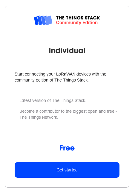
Anyone can start an account on the Discovery plan which is free, allowing users to have one gateway and ten devices. This is what I will be using with this challenge.
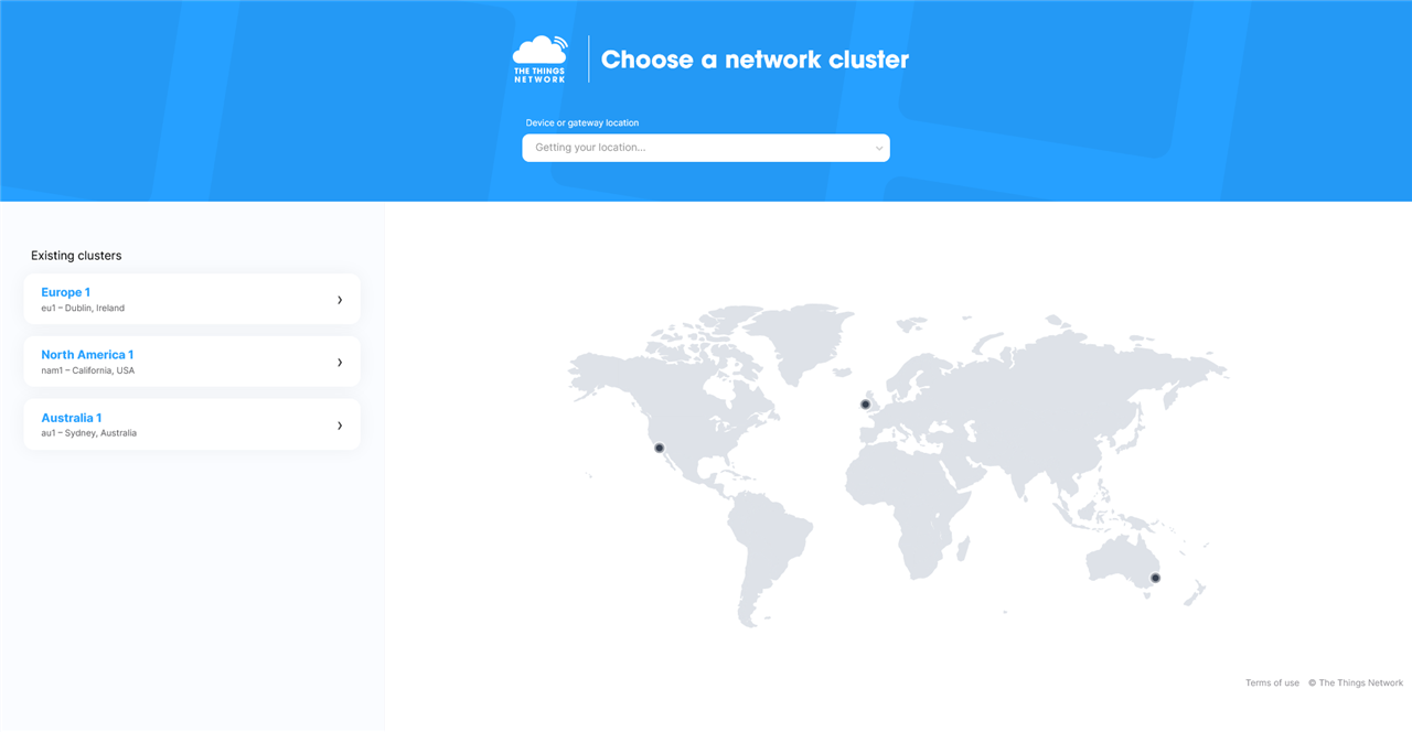
To sign-up, one will have to choose a network cluster to join. You should pick the cluster closest to you. I’m in Australia, so logically, I’m on the Australian cluster.
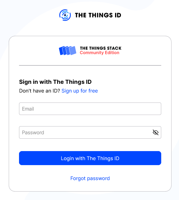
You’ll then be asked to login – but as a new user, you’ll have to create a new ID.
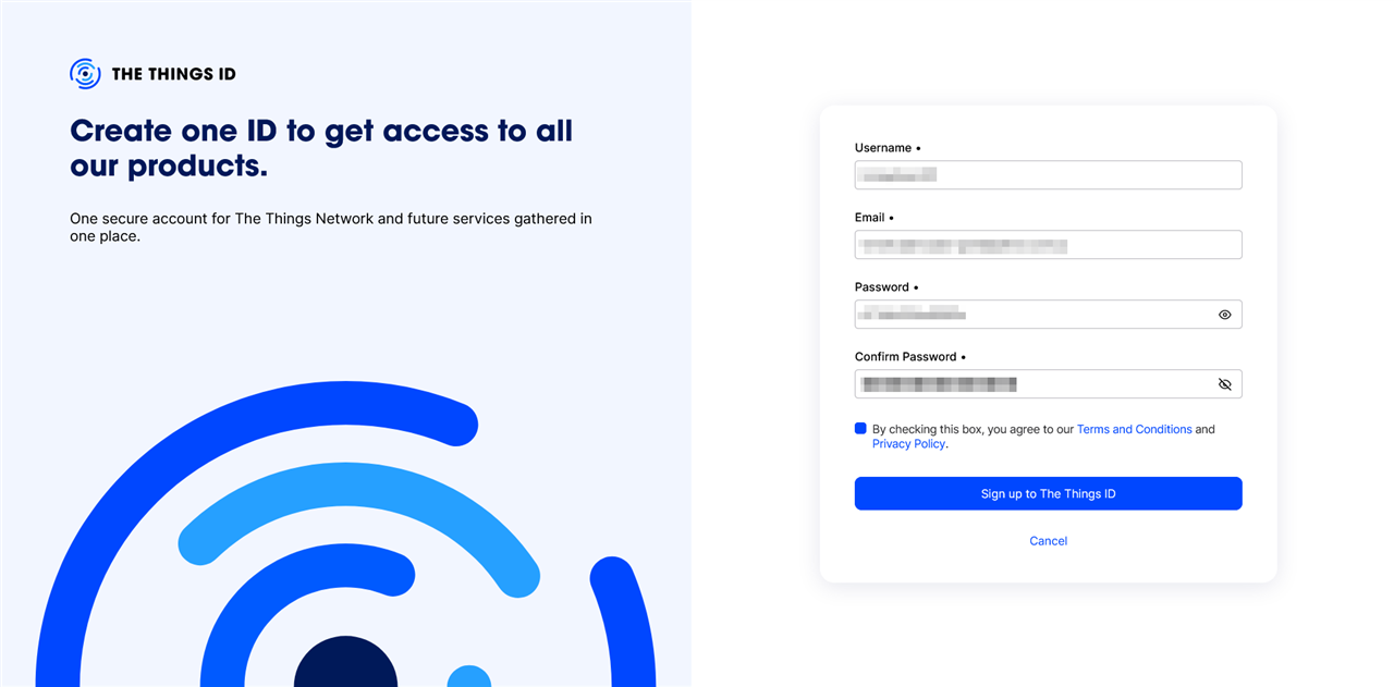
To do so requires filling in the form and submitting it, as well as validating your e-mail address. Once you’ve got that completed, you’ll be ready to go!
One thing to beware of is the presence of an Acceptable Use Policy which places restrictions on air time to 30 seconds per day with ten acknowledgements per day (for acknowledged messages). This will limit the number of messages and the size of data you can transmit in a day, which may change because of ADR.
If you’re wondering whether you can get coverage, there is a network map of gateways where the locations are public (not all gateways will have their location provided or made public). However, being near a gateway is no guarantee of coverage, as antenna choice, elevation and interference levels will limit the coverage. Most gateways are installed to support a commercial or building-level application and any coverage beyond this is a “bonus” for the community.
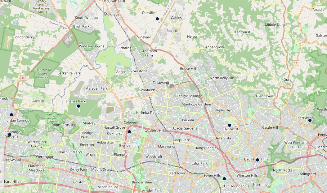
In my case, there are several stations within 1-2km of me, which gives me a little hope.
Getting Started with Arduino MKR WAN 1310
The first step in setting up was just a tiny modification to an old breadboard of mine to make it “LoRa-enabled” – simply a 6mm hole drilled out and reamed to 6.3mm to fit an SMA connector for the antenna, and a small cut-out made in the side for nicer routing of the pigtail coax with some hot glue to bed it all down.
Software-wise, to get started requires installing the Arduino IDE, then installing the Arduino SAMD Boards package, MKRWAN, LoRa by Sandeep Mistry, Arduino Low Power and Arduino_BQ24195 libraries to support all of the hardware. As this is pretty straightforward, I won’t be covering this part in any detail.
The first step was to update the firmware using the MKRWANFWUpdate_Standalone example sketch. Build it and load it to the board – it should update the firmware automatically.
Press a key to start FW update
Version      : 0x31
Option 1     : 0x00
Option 2     : 0x00
Device ID    : 0x0447 (STM32L07xxx/08xxx)
- RAM        : Up to 20KiB  (8192b reserved by bootloader)
- Flash      : Up to 192KiB (size first sector: 32x128)
- Option RAM : 32b
- System RAM : 8KiB
Write to memory
Erasing memory
Wrote and verified address 0x08000100 (0%)
Wrote and verified address 0x08000200 (0%)
[…]
Wrote and verified address 0x08014480 (100%)
Done.

Starting execution at address 0x08000000... done.
Flashing ok :)
ARD-078 1.2.3
Update completed, we can now start to connect it to The Things Network. I used the LoraSendAndReceive example and modified it a bit so that it sends a message containing the ASCII string “BEES” every 15-seconds while using the AU915 region (appropriate for where I am).
/*
  Lora Send And Receive
  This sketch demonstrates how to send and receive data with the MKR WAN 1300/1310 LoRa module.
  This example code is in the public domain.
  MODIFIED BY GOUGH LUI FOR ELEMENT14 SAVE THE BEES CHALLENGE MAR-2023
*/

#include <MKRWAN.h>

LoRaModem modem;

#include "arduino_secrets.h"
// Please enter your sensitive data in the Secret tab or arduino_secrets.h
String appEui = SECRET_APP_EUI;
String appKey = SECRET_APP_KEY;

void setup() {
  // put your setup code here, to run once:
  Serial.begin(115200);
  while (!Serial);
  // change this to your regional band (eg. US915, AS923, ...)
  if (!modem.begin(AU915)) {
    Serial.println("Failed to start module");
    while (1) {}
  };
  Serial.print("Your module version is: ");
  Serial.println(modem.version());
  Serial.print("Your device EUI is: ");
  Serial.println(modem.deviceEUI());
  int connected = 0;
  while (!connected) { // MODIFIED TO JOIN CONTINUOUSLY UNTIL CONNECTED
    Serial.println("Attempting to join network ...");
    connected = modem.joinOTAA(appEui, appKey);
  }

  // Set poll interval to 60 secs.
  modem.minPollInterval(60);
  // NOTE: independent of this setting, the modem will
  // not allow sending more than one message every 2 minutes,
  // this is enforced by firmware and can not be changed.
}

void loop() {
  Serial.println();
  Serial.println("Sending Message ... ");
  String msg = "BEES";

  Serial.println();
  Serial.print("Sending: " + msg + " - ");
  for (unsigned int i = 0; i < msg.length(); i++) {
    Serial.print(msg[i] >> 4, HEX);
    Serial.print(msg[i] & 0xF, HEX);
    Serial.print(" ");
  }
  Serial.println();

  int err;
  modem.beginPacket();
  modem.print(msg);
  modem.endPacket(false); // MODIFIED TO SEND UNACKNOWLEDGED TRANSMISSIONS

  delay(1000);
  if (!modem.available()) {
    Serial.println("No downlink message received at this time.");
  } else {
    char rcv[64];
    int i = 0;
    while (modem.available()) {
      rcv[i++] = (char)modem.read();
    }
    Serial.print("Received: ");
    for (unsigned int j = 0; j < i; j++) {
      Serial.print(rcv[j] >> 4, HEX);
      Serial.print(rcv[j] & 0xF, HEX);
      Serial.print(" ");
    }
  }
  Serial.println("Waiting for next TX");
  delay(15000); // MODIFIED TO SEND "BEES" MESSAGE EVERY 15S
}
I needed it to run once first, so I can read the EUI (similar to a MAC address) so I could add it to The Things Network, so using the default secrets should be just fine. In my case, the EUI was a8610a3334xxxxxx (last three bytes redacted).
To start, we have to register an application on The Things Network.
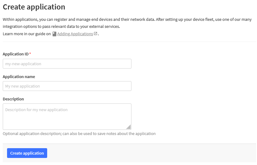
From there, we can add a device to the application.
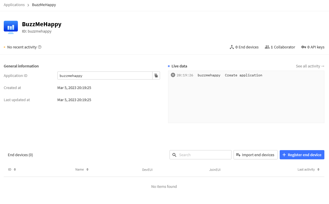
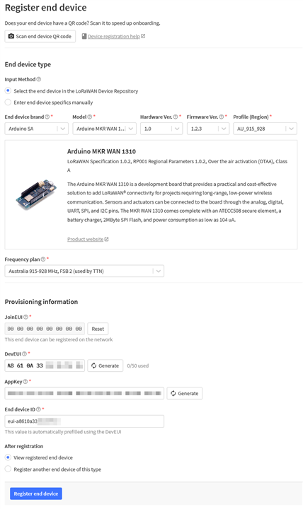
Thankfully, there are some presets for the Arduino MKR WAN 1310 with 1.2.3 firmware. The correct frequency band-plan must be chosen – in Australia, this is FSB 2. The Join EUI can be set to all-zeroes, as long as it matches what you have in the arduino_secrets.h file. Then you will need to generate an App Key, to which you then paste into the file as well.
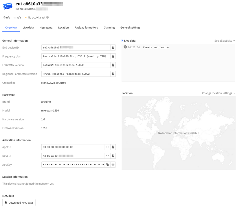
Then you should be led to the device status screen where there is a live update of the device status (if it has come online etc).
Then it is time to update the board with the new build containing the correct secrets and (in theory) it should join just fine. Unfortunately, in the end, none of my nearest bases could hear my board as all I got was:
Your module version is: ARD-078 1.2.3

Your device EUI is: a8610a3334xxxxxx

Something went wrong; are you indoor? Move near a window and retry
Of course, that was after double-checking everything – if one gets the wrong secrets, for example, they will receive the same error message. I even tried upstairs, holding my board out of a window but to no avail.
Conclusion
LoRa is short for long range, and is the physical layer modulation and coding of signal using chirped spread spectrum which allows for a low-data-rate exchange of digital information using low power over long distances. To make this into LoRaWAN requires observing the protocol stack that comes above it, which brings benefits including a per-device encryption, packet/application addressing, retransmission, frequency hopping/duty cycle and acknowledgements (for packets that require it). From there, the LoRaWAN stack in question will use an integration to pass this data onto another system that can handle it.
Setup is relatively straightforward and a minor modification was made to a breadboard to make it “LoRaWAN ready”. After setting up the device details and installing the example sketch, it was time to give it a try. Unfortunately, this didn’t work even though I had some gateways within about 1.8km of me.
It was hardly unexpected, given that the range figures often quoted for LoRaWAN connections are in the “ideal” circumstance. In a dense suburban environment, especially one with hills and limited line-of-sight, reaching your nearest The Things Network gateways is not a given. This is especially because the gateways may be implemented indoors to provide building-level coverage facility, with any external coverage being a “bonus”. Nevertheless, there may also be gateways without geographical information and packet broker coverage (which may not allow all packet types), so the only way to know whether you have coverage is just to try it.
That being said, I’m now all set-up for LoRaWAN from the MKR WAN 1310 via The Things Network Cloud’s stack. The problem is that my signal isn’t reaching a gateway … so let’s solve that problem by getting a gateway (and in return, give some of my neighbours some coverage too)!
[[BeeWatch Blog Index]]
- Blog 1: README.TXT
- Blog 2: Unboxing the Kit
- Blog 3: LoRa vs. LoRaWAN & Getting Started with MKR WAN 1310
- Blog 4: LoRaWAN Gateway Set-Up & MKR WAN 1310 Quirks
- Blog 5: Power, State Saving, Using Sensors & Battery
- Blog 6: Particulate Monitoring & Solar Power Input
- Blog 7: Powered by the Sun & Initial Data
- Blog 8: Getting Started with Nicla Vision
- Blog 9: Nicla Vision IR ToF & Audio Sensing, Data Dump
- Blog 10: Nicla Vision Power, Saving B’s & Dashboard Woes
- Blog 11: Summary Conclusion

