We were not able to achieve a connection in my last blog and the reason seemed very likely due to the fact that there are no gateways nearby that can hear the signal and establish a two-way communication with my MKR WAN 1310. To remedy this, some spending was required to acquire a LoRaWAN gateway and accessories to put it into commission. But alas, if things were this easy, this post would have gone up about a week earlier so instead, I’ve had to delay it as I worked to solve the quirks I encountered along the way.
Table of Contents
Establishing a Gateway
When the challenge started, I already had a feeling that I’d need a LoRaWAN gateway. As a result, I had already done some research into what gateways were locally available and perhaps the most flexible. There are not all that many choices, with most of them being quite pricey. In the end, between a choice of RAK Wireless, Dragino, SenseCAP, Milesight and Mikrotik products, some of which had older less-sensitive indoor chipsets, I settled on the Mikrotik KNOT LR9. While it doesn’t have the security-enhanced LoRa Basics Station mode, it does have GNSS input, the ability to work as a Bluetooth Low-Energy gateway, NTP server, RS-485 Bridge, Wi-Fi access-point/client/bridge, NB-IoT/LTE-M modem and had the ultimate routing flexibility with PoE in/out capability.
The gateway itself is pretty compact and came in at AU$343 with a matching 24V DC power adapter. As a professional device, it doesn’t come with any antennas, so I decided to splurge out on a GPS antenna (not pictured) for AU$15 and a multi-band HGO-LTE-W Antenna for indoor LoRaWAN/LTE-M for AU$15. Later on, I decided that it would be nice to make the gateway available for my area by using a high-gain 6.5dBi antenna mounted in the loft of my two-storey house – that set me back another AU$86. Now AU$459 poorer, I’ve got myself a decent LoRaWAN gateway!
On one side is an SMA connector for LoRaWAN. On another are two SMA connectors, one for GNSS and the other for LTE-M/NB-IoT. Bluetooth and Wi-Fi 2.4GHz antennas are internal.
The unit has a long array of LED indicators.
The back has the terminal blocks for RS-485, two Ethernet 100Mbit/s ports, a microUSB-OTG port, a slot for a NanoSIM and power barrel jack.
This device, while very cool in concept, gets quite hot in use. As a result, it is built on a cast metal base.
Under the covers, it’s clear that the Bluetooth/Wi-Fi antennas are a mixture of printed antennas on the bottom right corner for Wi-Fi (two spatial-streams) and a pressed metal antenna for Bluetooth in the bottom left. The LoRaWAN capability is provided by the R11e-LR9 card which is suited for 900MHz-band usage. In Europe, the LR8 card is used instead.
The first step was to start up the unit and update the software. Unfortunately, my unit arrived “dead” and would not boot properly. The LEDs were stuck and the unit was not reachable on any interface on its default 192.168.88.1 address, nor did it dole out any DHCP offers. As a result, I had to run a Netinstall of the latest RouterOS image along with IoT and LoRa package. This is best done on a Windows 7 or older machine, but can also be done on a newer machine with a few workarounds (including disabling the firewall, enabling compatibility mode for Windows 7 and running in administrator mode) although some people do report issues.
Once online, it is easiest to connect via Ethernet to the second port and start configuring interfaces. As I was to situate the unit in my loft where there is no Ethernet cabling, I configured the Wi-Fi to be WAN and set it into Station-Bridge mode for connection to my existing Mikrotik AP with a matching security profile. For non-Mikrotik APs, Station-Pseudobridge should be used instead. For first-time Mikrotik users, this may seem a little complicated, but you’ll get used to it. I ensured it got its WAN configuration via DHCP and could connect to the internet.
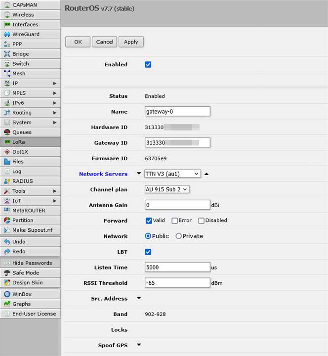
With the LoRa Module installed, we should first ensure the radio is disabled before configuring. In the configuration screen, you can read the Hardware ID which you will need for creating a gateway on The Things Network. In the meantime, configure the Network Servers to the one that matches your cluster selection and the Channel Plan to the one that matches your region. Set the antenna gain to the closest value to your antenna to ensure RSSIs are reported correctly (I did this later) and to forward only valid packets. Enabling Listen-Before-Talk (LBT) will help reduce the chances for collisions. Save the profile and do not enable the radio just yet.
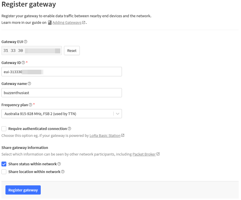
Next step would be to add a gateway into The Things Network with a matching Hardware ID. Once the profile is created, you can enable the radio.

All things working well, you should be able to see the gateway connect and send data at <= 30 second intervals. In my case, it was passing data literally within its first minute!
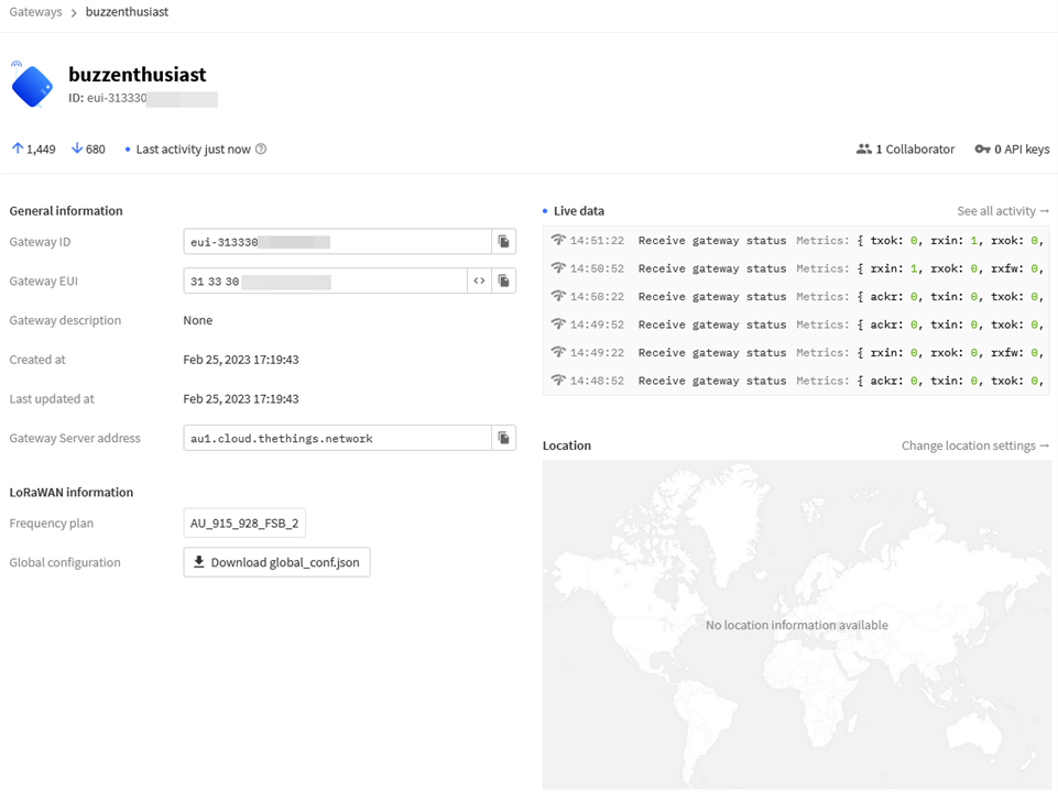
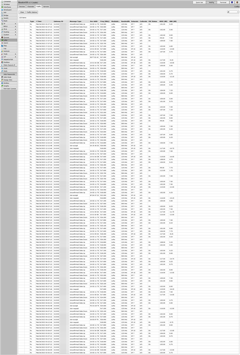
After a day of operation, the Mikrotik traffic log shows the last 120 packets indicating a low level of LoRaWAN activity near me that my gateway is participating in. This is before I even tried to get the MKR WAN 1310 working on my gateway. About a week in, my dashboard on The Things Network shows nearly 1500 frames uplinked and over 600 frames downlinked. My gateway is definitely doing some good work!
I’ve decided to put this gateway into operation in part for my own education, but also to help others in the area who may be interested in playing with LoRaWAN but aren’t otherwise able to get coverage. As a person without a truly permanent internet connection (I rely on LTE and hop providers every month), it’s not ideal for my limited quota or for latency, but some coverage is still better than none! For my own privacy, I have decided not to enable GNSS and have not connected the antenna to the gateway. I have not decided to expose my location to The Things Network either, even though the network could probably work it out (roughly) based on the mix of packets I am receiving.
Join Me Plenty!
With my sketch from last time and my LoRaWAN-enabled breadboard, I powered up expecting success – I am literally starting up the board right next to the gateway!
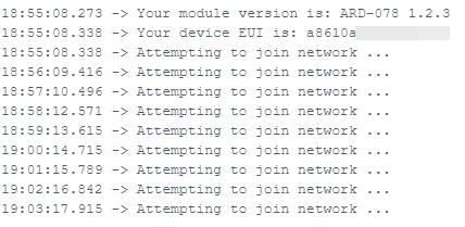
Somehow, it was not to be. The code tries to join, times out, tries again … and never actually gets connected.
Was my antenna bad? It was at this time, I regretted hot-gluing the connector to the board to avoid damage or accidents. But with a hot air gun, I melted the glue enough to remove the connection, hoping not to get it into the connector itself.
I swapped in a Molex multi-band flexible antenna instead and the results were similarly problematic. On occasion, it may seem to join … but data just never came through. It wasn’t the antenna … or so it seemed. What’s going on!?!
An Unreliable Link and Packet Brokers
By pure randomness, I found out that if you rebooted the board enough times, it will seemingly join –
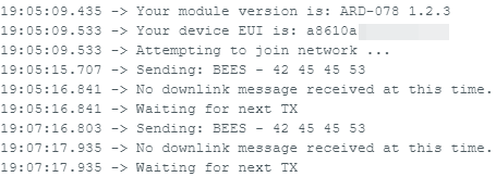
Thankfully my local gateway has a traffic monitor that helps a little with debugging.

It seems the first few join requests somehow have such a low signal to noise ratio that The Things Network just ignores it. But then, if the join occurs at the right frequency, the SNR is just fine so the LoRaWAN stack allows it to join.
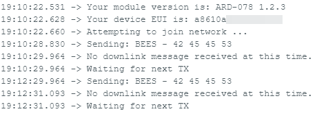
But once joined, it should be sending the string “BEES” over and over at two-minute intervals.

Instead, I see it join and then … nothing. No data whatsoever. Why is this?
A small breakthrough happened when I left the board running for a while and then saw a transmission getting picked up by another gateway but not my own!
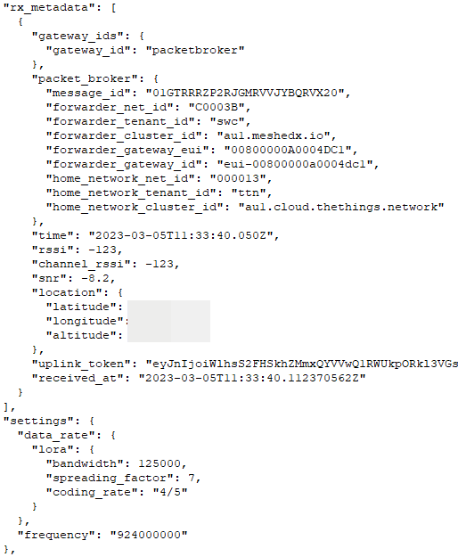
This particular packet came via Packet Broker, a LoRaWAN interexchange network that allows gateways from private systems to interoperate with each other to share coverage based on their own configurable rules which may limit which frame types are forwarded.

That may mean that you have coverage from a LoRaWAN gateway via packet broker that will forward data frames for existing devices that are already connected, but won’t allow you to join the network through that gateway.
Looking at this, the tenant ID of “swc” makes me suspect this gateway is operated by Meshed for Sydney Water Corporation to read water meters. The provided location co-ordinates seem to imply my frame has travelled 12.5km to that gateway! Wow! But did you notice – frequency 924MHz?
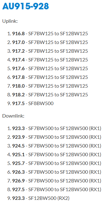
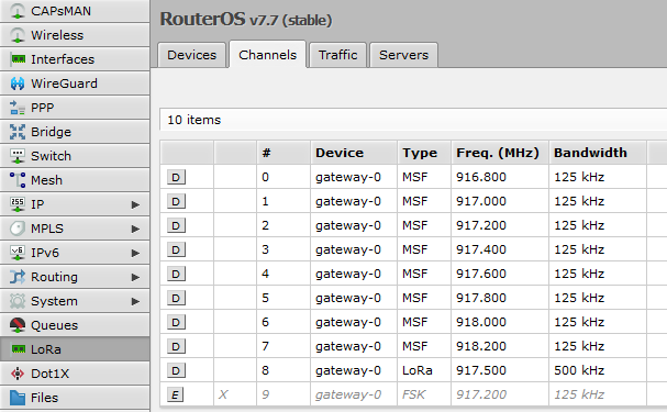
In Australia, the preferred band plan is AU915 using Frequency Sub-Band 2 (FSB2). A look at the listed frequencies confirms that my gateway is correctly configured for AU915-FSB2 operation. But 924MHz is not part of AU915 at all! My board is transmitting on the wrong frequencies and is not getting heard. But as it turns out, 924MHz is part of the AS923 band plan which is permitted to be operated in Australia but not preferred. Many private networks are operating in AS923 because of the proliferation of older imported equipment that supports AS923 and not AU915, hence why my transmission got picked up by a Packet Broker gateway!
As a result, it seems that setting the region on the MKR WAN 1310 sketch to AU915 is not sufficient. It tries joining on frequencies it shouldn’t and it transmits on frequencies that it shouldn’t either. The cause is also due to a peculiarity with LoRaWAN itself.
Making it Work
How do we recover from these issues? The first thing is to ensure the MKR WAN 1310 is only allowed to use the channels that our region permits. Thankfully, a channel mask example is given on Arduino’s MKRWAN library documentation that has been calculated for AU915. Just don’t use this one which was the one I found first and is incorrect.
But that, on its own, is not enough. It seems the default settings on The Things Network for an Arduino MKR WAN 1310 with 1.2.3 firmware is not correct.
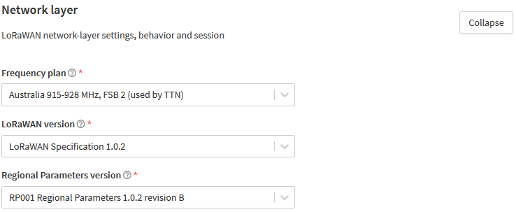
Specifically, the Regional Parameters version is set to RP001 Regional Parameters 1.0.2 by default. I found that I needed to set it to revision B for it to operate correctly.
This is a peculiarity of LoRaWAN as the bit-mapping of the PHY-level control frames changes between LoRaWAN versions and each set of versions has a set of matching regional parameters. If you don’t know which “set” the device is using, the stack may think it’s telling the device to use a certain set of frequencies, but the device will interpret this incorrectly and end up transmitting on the wrong frequencies which can be difficult to troubleshoot as it could lead to intermittent losses (e.g. 1/8 transmissions in the case of one misconfigured channel). It can also cause advanced features such as adaptive data rate (ADR) to fail. The only real way is trial-and-error if you don’t know … I tried LoRaWAN Specification 1.0.3 and ended up with reliable joins but wrong frequencies, for example.
My evolved sample code, appropriate for AU915 usage, is as below:
/*
  Lora Send And Receive
  This sketch demonstrates how to send and receive data with the MKR WAN 1300/1310 LoRa module.
  This example code is in the public domain.
  MODIFIED BY GOUGH LUI FOR ELEMENT14 SAVE THE BEES CHALLENGE MAR-2023
*/

#include <MKRWAN.h>

LoRaModem modem;

// Uncomment if using the Murata chip as a module
// LoRaModem modem(Serial1);

#include "arduino_secrets.h"
// Please enter your sensitive data in the Secret tab or arduino_secrets.h
String appEui = SECRET_APP_EUI;
String appKey = SECRET_APP_KEY;

int cnt = 0;

void setup() {
  Serial.begin(115200);
  while (!Serial);
  // change this to your regional band (eg. US915, AS923, ...)
  if (!modem.begin(AU915)) {
    Serial.println("Failed to start module");
    while (1) {}
  };
  Serial.print("Your module version is: ");
  Serial.println(modem.version());
  Serial.print("Your device EUI is: ");
  Serial.println(modem.deviceEUI());
  // From https://docs.arduino.cc/tutorials/mkr-wan-1310/lorawan-regional-parameters
  modem.sendMask("ff000000f000ffff00020000");
  int connected = 0;
  while (!connected) {
    Serial.println("Attempting to join network ...");
    connected = modem.joinOTAA(appEui, appKey);
  }

  // Set poll interval to 60 secs.
  modem.minPollInterval(60);
  // NOTE: independent of this setting, the modem will
  // not allow sending more than one message every 2 minutes,
  // this is enforced by firmware and can not be changed.
}

void loop() {
  String msg = "BEES";
  Serial.print("Sending: " + msg + " - ");
  for (unsigned int i = 0; i < msg.length(); i++) {
    Serial.print(msg[i] >> 4, HEX);
    Serial.print(msg[i] & 0xF, HEX);
    Serial.print(" ");
  }
  Serial.println();

  int err;
  modem.beginPacket();
  modem.print(msg);
  modem.endPacket(false);

  delay(1000);
  if (!modem.available()) {
    Serial.println("No downlink message received at this time.");
  } else {
    char rcv[64];
    int i = 0;
    while (modem.available()) {
      rcv[i++] = (char)modem.read();
    }
    Serial.print("Received: ");
    for (unsigned int j = 0; j < i; j++) {
      Serial.print(rcv[j] >> 4, HEX);
      Serial.print(rcv[j] & 0xF, HEX);
      Serial.print(" ");
    }
  }
  Serial.println("Waiting for next TX");
  delay(120000); // 2 minute intervals
}
With these changes, I now have reliable LoRaWAN connectivity – see the two-minute transmit intervals very clearly showing in the log:
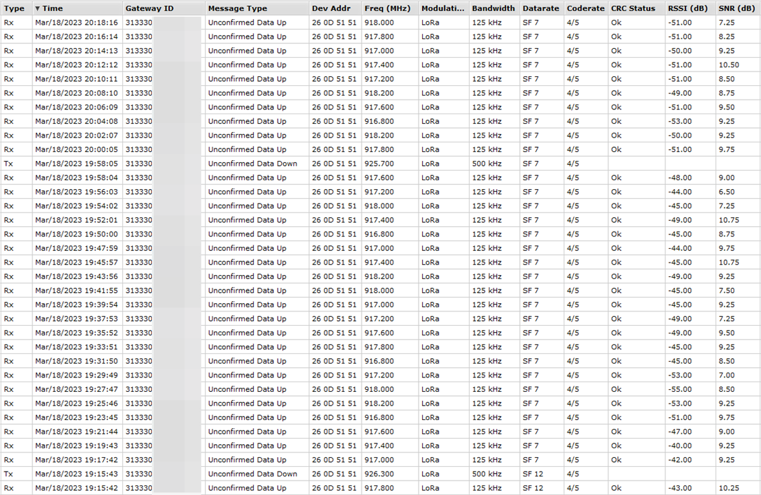
Even the case of ADR seems to be working properly. The cause of the initial low-SNR join request is not known, but it resulted in the board using the slowest SF12 transmit mode for a bit. But as more frames with high SNR came in, The Things Network Stack sent PHY downlinks to the board to tell it to kick up speed. The board then snaps into SF8, the second-fastest mode while the stack continues to observe signal strengths. As the strength is stable and good, the stack decides to kick the board up further to the fastest SF7 mode where it stays. This gives me confidence that I have found the right combination of settings.

Data rate optimisation is important as the airtime is a shared resource. We need to ensure that a single device doesn’t “hog” the air so much that other devices can’t get through. As a result, the “free” Things Network sets a fair-use policy of 30 seconds of airtime per device per day.

Using this calculator, it is possible to calculate your message budget depending on the data rate (DRx). Assuming you’re in AU915 as I am, and you want to send a 20-byte payload (packing environmental data), if you have the fastest DR5 (SF7) mode, you can send your message (unacknowledged) at an average of 207.2s intervals (or 17.4 times per hour) before you run out of airtime. However, if you’re further from the gateway or have a poorer connection, you will need more interval – at DR4, this is 384.9s between messages, at DR3 this is 710.7s between messages. If the connection is only good enough to support DR2 to DR0, it is not possible to send this message without exceeding dwell time limitations (although it is still under debate whether this applies in the AU-region).
Because of these limitations, it’s clear that such systems are not well suited for high-frequency real-time updating and on-device intelligence and efficient ways of coding data will be necessary to conserve bandwidth and energy.
Conclusion
The choice of a good LoRaWAN gateway usually comes at a significant cost and in my case, this was no exception. My choice of the Mikrotik KNOT LR9 was made primarily on flexibility as it has many modes of connectivity and nearly endless configurability and GNSS to boot, although it is not ideal from a LoRa perspective as it only supports the less-secure Semtech UDP Packet Forwarder protocol. Every good gateway needs a decent antenna, so I opted for a matching 6.5dBi outdoor antenna, mounted in my loft of a two-storey house built on the side of a hill. Linking to my main network via Wi-Fi, I was collecting packets from the air within minutes.
The MKR WAN 1310 side of things was a lot more frustrating. Not only was the problem not only a signal strength issue, there are MAC-level issues which are somewhat specific to AU915 region and The Things Network’s defaults. Because of this, strange situations occurred where join requests were completed intermittently and then no data transfer actually could take place because the board was steered to the wrong frequency. Worse still, some sites had the wrong information resulting in a partial fix that resulted in some data getting through on some frequencies and not on others. At times, this even resulted in transmissions off AU915-band and into AS923-band which we are also permitted to run in Australia but are discouraged from using, resulting in the packets being picked up by another AS923 gateway via Packet Broker but not my own. Impressively, that was over a 12km range!
Because of all the troubleshooting, I ended up undoing my nice antenna and struggling to remove the hot glue that I prematurely drizzled over the IPEX connector. In the end, it wasn’t an antenna problem at all … but a wild goose chase of different configuration changes that were necessary to make it all work. Add to this that the sample code from MKRWAN is not very well written, with returns scattered everywhere making modification a bit of a trap for the uninitiated. But I suppose this is a case of persistence paying off, to some extent.
Now that I’m joining reliably and Adaptive Data Rate (ADR) is working correctly, I’m confident that LoRaWAN will be able to connect my board to The Things Network’s servers. However, this is not all that needs to be done – in future posts, I’ll be looking at the power consumption of the MKR WAN 1310, how it can be put into sleep to conserve battery, whether we can save the join request keying data so that we don’t rejoin the network at every wake (as that’s terrible LoRaWAN practice) and how to integrate my intended sensors with the board. Only then will I have the impetus to worry about a source of energy (i.e. solar power) and a rechargeable battery to tie over the dark hours.
[[BeeWatch Blog Index]]
- Blog 1: README.TXT
- Blog 2: Unboxing the Kit
- Blog 3: LoRa vs. LoRaWAN & Getting Started with MKR WAN 1310
- Blog 4: LoRaWAN Gateway Set-Up & MKR WAN 1310 Quirks
- Blog 5: Power, State Saving, Using Sensors & Battery
- Blog 6: Particulate Monitoring & Solar Power Input
- Blog 7: Powered by the Sun & Initial Data
- Blog 8: Getting Started with Nicla Vision
- Blog 9: Nicla Vision IR ToF & Audio Sensing, Data Dump
- Blog 10: Nicla Vision Power, Saving B’s & Dashboard Woes
- Blog 11: Summary Conclusion


Top Comments