


In the last blog, I was able to stabilise the LoRaWAN connectivity, so now it’s time to explore the issue of MKR WAN 1310 power consumption, improving the sleep power consumption, how modem state saves could be implemented, integrating some environmental sensors as I had originally promised and making it “untethered” by giving it a rechargeable battery.
Table of Contents
Power Consumption Measurements
To measure power, I started off with the example sketch in the previous blog and employed the Keithley 2450 SMU in 1A current range (due to current peaks requiring >100mA). I connected the power through to the JST header for the battery, to bypass any additional quiescent current and loads from the USB port.

Starting up and doing an SF12 transmission, we can see that the transmit burst reaches 125mA while the quiescent current is 13.72mA. The long transmit time allows the signal to reach further, at the cost of energy, costing 160nWh for the transmission. Smaller blips are visible post transmission which seem to correspond to RX1 and RX2 receive windows.
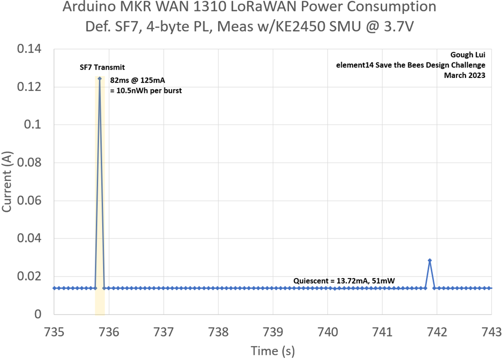
Later, the board kicked into SF7 mode, which shortened transmissions significantly to the point the SMU’s default 1 NPLC mode struggled to resolve the length of the burst accurately. I estimated an energy requirement of 10.5nWh.
But there is more to be had from the board – notably the use of the Arduino Low Power library. I modified the code to use the library and to take some hints from this thread to disable the USB connectivity to minimise power.
/*
  Lora Send And Receive - LOW POWER
  This sketch demonstrates how to send and receive data with the MKR WAN 1300/1310 LoRa module.
  This example code is in the public domain.
  MODIFIED BY GOUGH LUI FOR ELEMENT14 SAVE THE BEES CHALLENGE MAR-2023
*/

#include <MKRWAN.h>
#include "ArduinoLowPower.h"

LoRaModem modem;

// Uncomment if using the Murata chip as a module
// LoRaModem modem(Serial1);

#include "arduino_secrets.h"
// Please enter your sensitive data in the Secret tab or arduino_secrets.h
String appEui = SECRET_APP_EUI;
String appKey = SECRET_APP_KEY;

void setup() {
  USBDevice.detach(); // No USB to save power

  // change this to your regional band (eg. US915, AS923, ...)
  if (!modem.begin(AU915)) {
    while (1) {}
  };

  // From https://docs.arduino.cc/tutorials/mkr-wan-1310/lorawan-regional-parameters
  modem.sendMask("ff000000f000ffff00020000");
  int connected = 0;
  while (!connected) {
    connected = modem.joinOTAA(appEui, appKey);
  }

  // Set poll interval to 60 secs.
  modem.minPollInterval(60);
  // NOTE: independent of this setting, the modem will
  // not allow sending more than one message every 2 minutes,
  // this is enforced by firmware and can not be changed.
}

void loop() {
  String msg = "BEES";

  modem.beginPacket();
  modem.print(msg);
  modem.endPacket(false);

  delay(1000);
  if (modem.available()) {
    char rcv[64];
    int i = 0;
    while (modem.available()) {
      rcv[i++] = (char)modem.read();
    }
  }
  LowPower.deepSleep(120000); // 2 minute intervals
}
Unfortunately, the low power code worked too well, such that the KE2450 SMU couldn’t accurately resolve the current consumption while in sleep.

Because of the issue of burden resistance causing significant voltage drops, using a DMM to measure the current would also be rather tricky especially as the power goes from 125mA+ during transmission down to <1mA in sleep.

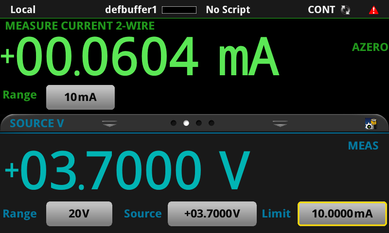
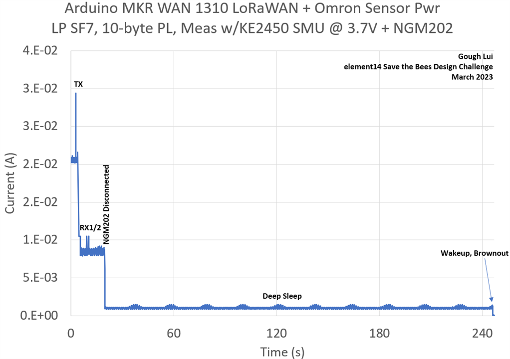
I decided to use a bit of an unorthodox arrangement with the help of my Rohde & Schwarz NGM202 to provide the bulk current during transmit bursts in source-only mode. Unfortunately, it will sink some current despite being in source-only mode, so as soon as I’m confident the device has gone into sleep, I disconnect the NGM202 entirely leaving the KE2450 supplying all of the power to the MKR WAN 1310 in sleep. I selected 10mA range on the KE2450 as this allows for more resolution, although I did try 1mA and it seemed that the transient of disconnection caused the board to brownout causing a falsely-low current measurement.
Using this technique, it implies the standby current of the MKR WAN 1310 is as low as 60.4µA! That’s very impressive. The graphs provide much better justification of this measurement –
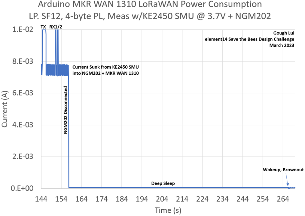
The transmission of SF12, RX1/RX2 windows are clearly visible. Once disconnecting the NGM202, we can see the deep sleep current. At 120s further down, it’s clear that a wakeup is attempted and brownout seems to occur, causing a noisy current trace (this proving the unit was happy in deep sleep and didn’t crash until then).
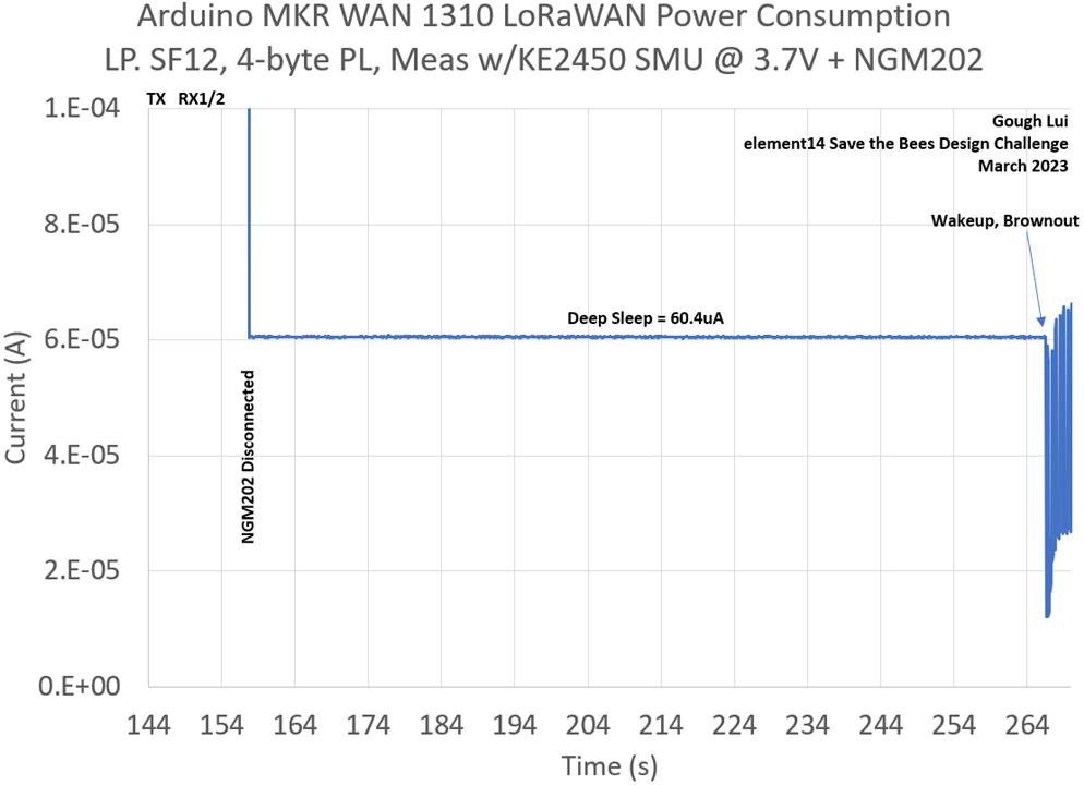
Zooming in, the deep sleep current is very stable, averaging 60.4µA. With such a low standby current, is there any need to save modem states anymore? The board alone would only eat 530mAh per year, which is pretty good for a prototyping board! More savings are likely to be had for well-designed solutions.
Saving Private Ryan LoRaWAN Modem State
In many devices which need to be powered down into the deepest sleep to achieve the lowest power consumption, the LoRaWAN modem is turned off and thus loses all of its state. Should that actually occur, the modem would need to complete a fresh join request every time it woke up, taking a lot of airtime and energy to achieve this.
Instead, the state of the modem should be recorded before the board goes to sleep – this includes things such as the network keys, device ID, frame counters and more. If it can be restored before the next transmission occurs, then it will be as if the LoRaWAN device never actually left the network!
That being said, for the MKR WAN 1310, this appears to be moot as the board has such a low quiescent power draw given a minimal amount of work that it should just last for sufficient amounts of time without the need to save state.
However, the predecessor MKR WAN 1310 had design issues that resulted in much higher standby currents, which led AmedeeBulle to create a way to save and restore modem state and use an external circuit to turn on the board at given intervals – see https://github.com/AmedeeBulle/TTNMkrWanNode
A key issue is that some values, such as frame count, are updated at each transmission. Therefore, unless you have a high-endurance non-volatile memory to store the value into, saving it could cause wearout of traditional EEPROM and Flash memory. For this reason, the suggested code uses an external FRAM which has no such cycle limitations, but is something I don’t have. As I’ve decided from the previous results just to go without saving the modem state as the sleep power is sufficiently low, I don’t think we need to investigate this any further.
Adding Sensors
Thanks to being a RoadTester for the Omron 2JCIE-EV01-AR1 in August 2020, I’ve already got myself a nice “shield” that can plug onto the MKR WAN 1310 without the need to design or build anything. I decided to take this shortcut because the board has temperature, humidity and barometer measurements which are relevant to the environmental monitoring I had proposed.
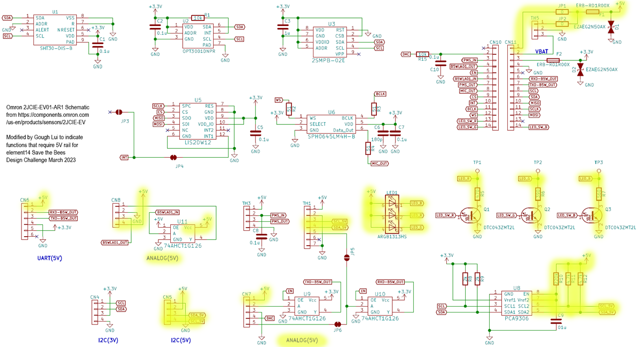
Looking closely at the schematic, however, makes it clear that some sensors and the RGB LEDs require the use of 5V, including the dust and smoke sensor which I had reviewed. Unfortunately, due to the design of the MKR WAN 1310 which does not generate a boosted 5V rail from the battery to reduce energy consumption, unfortunately, I have to give up on that sensor. I did look at alternative laser-particulate monitor sensors, but almost all universally require 5V for powering their internal fan even if communication is at 3.3V, which complicates things.
An option would be to generate a switchable 5V rail which can be powered on when required by the microcontroller through a switching controller’s enable pin. This may be an option if I were intending to make this a serious device. Another option would be to use USB/5V into Vin on the board and an external boost and battery management. However, the quiescent current of the converter under light loads could be a problem and the MKR WAN 1310 may not be as efficient when powered via USB as loads such as the LEDs and PMIC are connected.
I consolidated the code in such a way that it became part of the sketch, as it was originally provided as such rather than in library format.
/*
  Lora Send And Receive + OMRON 2JCIE-EV Environmental Sensors
  MODIFIED BY GOUGH LUI FOR ELEMENT14 SAVE THE BEES CHALLENGE MAR-2023
  Based on Omron sample code from:
  https://github.com/omron-devhub/2jcieev01-arduino
*/

#include <MKRWAN.h>
#include <Wire.h>
#include <Arduino.h>
#include <SPI.h>
#include "ArduinoLowPower.h"

#define SHT30_ADDR  0x44
#define SHT30_STATUSMASK  0xFC1F
#define SHT30_READSTATUS           0xF32D
#define SHT30_CLEARSTATUS          0x3041
#define SHT30_SOFTRESET            0x30A2
#define SHT30_HEATEREN             0x306D
#define SHT30_HEATERDIS            0x3066
#define SHT30_MEAS_HIGHPRD         0x2334
#define SHT30_READ_PERIODIC        0xE000
#define BARO_2SMPB02E_CHIP_ID     0x5C
#define BARO_2SMPB02E_ADDRESS                (0x56)
#define BARO_2SMPB02E_REGI2C_PRES_TXD2               0xF7
#define BARO_2SMPB02E_REGI2C_IO_SETUP                0xF5
#define BARO_2SMPB02E_REGI2C_CTRL_MEAS               0xF4
#define BARO_2SMPB02E_REGI2C_IIR                     0xF1
#define BARO_2SMPB02E_REGI2C_CHIP_ID                 0xD1
#define BARO_2SMPB02E_REGI2C_COEFS                   0xA0
#define BARO_2SMPB02E_VAL_IOSETUP_STANDBY_0001MS       ((uint8_t)0x00)
#define BARO_2SMPB02E_VAL_IOSETUP_STANDBY_0125MS       ((uint8_t)0x20)
#define BARO_2SMPB02E_VAL_IOSETUP_STANDBY_0250MS       ((uint8_t)0x40)
#define BARO_2SMPB02E_VAL_IOSETUP_STANDBY_0500MS       ((uint8_t)0x60)
#define BARO_2SMPB02E_VAL_IOSETUP_STANDBY_1000MS       ((uint8_t)0x80)
#define BARO_2SMPB02E_VAL_IOSETUP_STANDBY_2000MS       ((uint8_t)0xA0)
#define BARO_2SMPB02E_VAL_IOSETUP_STANDBY_4000MS       ((uint8_t)0xC0)
#define BARO_2SMPB02E_VAL_IOSETUP_STANDBY_8000MS       ((uint8_t)0xE0)
#define BARO_2SMPB02E_VAL_TEMPAVERAGE_01     ((uint8_t)0x20)
#define BARO_2SMPB02E_VAL_TEMPAVERAGE_02     ((uint8_t)0x40)
#define BARO_2SMPB02E_VAL_TEMPAVERAGE_04     ((uint8_t)0x60)
#define BARO_2SMPB02E_VAL_PRESAVERAGE_01    ((uint8_t)0x04)
#define BARO_2SMPB02E_VAL_PRESAVERAGE_02    ((uint8_t)0x08)
#define BARO_2SMPB02E_VAL_PRESAVERAGE_04    ((uint8_t)0x0C)
#define BARO_2SMPB02E_VAL_PRESAVERAGE_08    ((uint8_t)0x10)
#define BARO_2SMPB02E_VAL_PRESAVERAGE_16    ((uint8_t)0x14)
#define BARO_2SMPB02E_VAL_PRESAVERAGE_32    ((uint8_t)0x18)
#define BARO_2SMPB02E_VAL_POWERMODE_SLEEP  ((uint8_t)0x00)
#define BARO_2SMPB02E_VAL_POWERMODE_FORCED ((uint8_t)0x01)
#define BARO_2SMPB02E_VAL_POWERMODE_NORMAL ((uint8_t)0x03)
#define BARO_2SMPB02E_VAL_IIR_OFF     ((uint8_t)0x00)
#define BARO_2SMPB02E_VAL_IIR_02TIMES ((uint8_t)0x01)
#define BARO_2SMPB02E_VAL_IIR_04TIMES ((uint8_t)0x02)
#define BARO_2SMPB02E_VAL_IIR_08TIMES ((uint8_t)0x03)
#define BARO_2SMPB02E_VAL_IIR_16TIMES ((uint8_t)0x04)
#define BARO_2SMPB02E_VAL_IIR_32TIMES ((uint8_t)0x05)
#define BARO_2SMPB02E_COEFF_S_A1   ((double)( 4.3E-04))
#define BARO_2SMPB02E_COEFF_A_A1   ((double)(-6.3E-03))
#define BARO_2SMPB02E_COEFF_S_A2   ((double)( 1.2E-10))
#define BARO_2SMPB02E_COEFF_A_A2   ((double)(-1.9E-11))
#define BARO_2SMPB02E_COEFF_S_BT1  ((double)( 9.1E-02))
#define BARO_2SMPB02E_COEFF_A_BT1  ((double)( 1.0E-01))
#define BARO_2SMPB02E_COEFF_S_BT2  ((double)( 1.2E-06))
#define BARO_2SMPB02E_COEFF_A_BT2  ((double)( 1.2E-08))
#define BARO_2SMPB02E_COEFF_S_BP1  ((double)( 1.9E-02))
#define BARO_2SMPB02E_COEFF_A_BP1  ((double)( 3.3E-02))
#define BARO_2SMPB02E_COEFF_S_B11  ((double)( 1.4E-07))
#define BARO_2SMPB02E_COEFF_A_B11  ((double)( 2.1E-07))
#define BARO_2SMPB02E_COEFF_S_BP2  ((double)( 3.5E-10))
#define BARO_2SMPB02E_COEFF_A_BP2  ((double)(-6.3E-10))
#define BARO_2SMPB02E_COEFF_S_B12  ((double)( 7.6E-13))
#define BARO_2SMPB02E_COEFF_A_B12  ((double)( 2.9E-13))
#define BARO_2SMPB02E_COEFF_S_B21  ((double)( 1.2E-14))
#define BARO_2SMPB02E_COEFF_A_B21  ((double)( 2.1E-15))
#define BARO_2SMPB02E_COEFF_S_BP3  ((double)( 7.9E-17))
#define BARO_2SMPB02E_COEFF_A_BP3  ((double)( 1.3E-16))
#define BARO_2SMPB02E_VAL_MEASMODE_HIGHSPEED (BARO_2SMPB02E_VAL_PRESAVERAGE_02 | BARO_2SMPB02E_VAL_TEMPAVERAGE_01)
#define BARO_2SMPB02E_VAL_MEASMODE_LOWPOWER (BARO_2SMPB02E_VAL_PRESAVERAGE_04 | BARO_2SMPB02E_VAL_TEMPAVERAGE_01)
#define BARO_2SMPB02E_VAL_MEASMODE_STANDARD (BARO_2SMPB02E_VAL_PRESAVERAGE_08 | BARO_2SMPB02E_VAL_TEMPAVERAGE_01)
#define BARO_2SMPB02E_VAL_MEASMODE_HIGHACCURACY (BARO_2SMPB02E_VAL_PRESAVERAGE_16 | BARO_2SMPB02E_VAL_TEMPAVERAGE_02)
#define BARO_2SMPB02E_VAL_MEASMODE_ULTRAHIGH (BARO_2SMPB02E_VAL_PRESAVERAGE_32 | BARO_2SMPB02E_VAL_TEMPAVERAGE_04)
#define OPT3001_ADDR  0x45
#define OPT3001_REG_RESULT          0x00
#define OPT3001_REG_CONFIG          0x01
#define OPT3001_REG_LOLIMIT         0x02
#define OPT3001_REG_HILIMIT         0x03
#define OPT3001_REG_MANUFACTUREID   0x7E
#define OPT3001_DEVICEID            0x7F
#define OPT3001_CMD_CONFIG_MSB      0xC6
#define OPT3001_CMD_CONFIG_LSB      0x10
#define conv16_u8_h(a) (uint8_t)(a >> 8)
#define conv16_u8_l(a) (uint8_t)(a & 0xFF)
#define conv8s_u16_be(b, n) (uint16_t)(((uint16_t)b[n] << 8) | (uint16_t)b[n + 1])
#define conv8s_s24_be(a, b, c) (int32_t)((((uint32_t)a << 16) & 0x00FF0000) | (((uint32_t)b << 8) & 0x0000FF00) | ((uint32_t)c & 0x000000FF))
#define halt(a) {Serial.println(a); while (1) {}}

LoRaModem modem;

typedef struct baro_2smpb02e_setting {
    double _A0, _A1, _A2;
    double _B00, _BT1, _BP1;
    double _B11, _BT2, _BP2;
    double _B12, _B21, _BP3;
} baro_2smpb02e_setting_t;

baro_2smpb02e_setting_t baro_2smpb02e_setting;

// Uncomment if using the Murata chip as a module
// LoRaModem modem(Serial1);

#include "arduino_secrets.h"
// Please enter your sensitive data in the Secret tab or arduino_secrets.h
String appEui = SECRET_APP_EUI;
String appKey = SECRET_APP_KEY;

bool i2c_write_reg16(uint8_t slave_addr, uint16_t register_addr, uint8_t *write_buff, uint8_t len) {
    Wire.beginTransmission(slave_addr);
    Wire.write(conv16_u8_h(register_addr));
    Wire.write(conv16_u8_l(register_addr));
    if (len > 0) {
        for (uint8_t i = 0; i < len; i++) {
            Wire.write(write_buff[i]);
        }
    }
    Wire.endTransmission();
    return false;
}

bool i2c_read_reg16(uint8_t slave_addr, uint16_t register_addr, uint8_t *read_buff, uint8_t len) {
    i2c_write_reg16(slave_addr, register_addr, NULL, 0);
    Wire.requestFrom(slave_addr, len);
    if (Wire.available() != len) {
        return true;
    }
    for (uint16_t i = 0; i < len; i++) {
        read_buff[i] = Wire.read();
    }
    return false;
}

bool i2c_write_reg8(uint8_t slave_addr, uint8_t register_addr, uint8_t *write_buff, uint8_t len) {
    Wire.beginTransmission(slave_addr);
    Wire.write(register_addr);
    if (len != 0) {
        for (uint8_t i = 0; i < len; i++) {
            Wire.write(write_buff[i]);
        }
    }
    Wire.endTransmission();
    return false;
}

bool i2c_read_reg8(uint8_t slave_addr, uint8_t register_addr, uint8_t *read_buff, uint8_t len) {
    i2c_write_reg8(slave_addr, register_addr, NULL, 0);
    Wire.requestFrom(slave_addr, len);
    if (Wire.available() != len) {
        return true;
    }
    for (uint16_t i = 0; i < len; i++) {
        read_buff[i] = Wire.read();
    }
    return false;
}

void sht30_setup() {
    i2c_write_reg16(SHT30_ADDR, SHT30_SOFTRESET, NULL, 0);
    delay(10);
    uint16_t stat = 0;
    i2c_write_reg16(SHT30_ADDR, SHT30_CLEARSTATUS, NULL, 0);
    delay(1);
    int retry = 10;
    do {
        stat = sht30_readstatus();  // check status
        delay(10);
    } while (((stat & SHT30_STATUSMASK) != 0x0000) && (retry-- > 0));
    if (((stat & SHT30_STATUSMASK) != 0x0000) || (retry == 0)) {
        halt("cannot detect SHT30 working.");
    }
    i2c_write_reg16(SHT30_ADDR, SHT30_MEAS_HIGHPRD, NULL, 0);
}

uint16_t sht30_readstatus(void) {
    bool result;
    uint8_t readbuffer[3] = {0, 0, 0};
    uint16_t stat = 0xFFFF;
    result = i2c_read_reg16(SHT30_ADDR, SHT30_READSTATUS, readbuffer, 3);
    if (!result) {
        stat = conv8s_u16_be(readbuffer, 0);
    }
    return stat;
}

int sht30_readTempHumi(int32_t* humi, int32_t* temp) {
    bool result;
    uint8_t readbuffer[6];
    result = i2c_read_reg16(SHT30_ADDR, SHT30_READ_PERIODIC, readbuffer, 6);
    if (result) {
        return 1;
    }
    if (readbuffer[2] != sht30_crc8(readbuffer, 2)) {
        return 2;
    }
    if (readbuffer[5] != sht30_crc8(readbuffer + 3, 2)) {
        return 3;
    }
    uint16_t ST, SRH;
    ST = conv8s_u16_be(readbuffer, 0);
    SRH = conv8s_u16_be(readbuffer, 3);
    double stemp = (double)ST * 17500.0 / 65535.0 - 4500.0;
    *temp = (int32_t)stemp;
    double shum = (double)SRH * 10000.0 / 65535.0;
    *humi = (int32_t)shum;
    return 0;
}

uint8_t sht30_crc8(const uint8_t *data, int len) {
    const uint8_t POLYNOMIAL(0x31);
    uint8_t crc(0xFF);
    for (int j = len; j; --j) {
        crc ^= *data++;
        for (int i = 8; i; --i) {
            crc = (crc & 0x80) ? (crc << 1) ^ POLYNOMIAL : (crc << 1);
        }
    }
    return crc;
}

bool baro_2smpb02e_setup(void) {
    bool result;
    uint8_t rbuf[32] = {0};
    uint8_t ex;
    result = i2c_read_reg8(BARO_2SMPB02E_ADDRESS, BARO_2SMPB02E_REGI2C_CHIP_ID, rbuf, 1);
    if (result || rbuf[0] != BARO_2SMPB02E_CHIP_ID) {
        halt("cannot find 2SMPB-02E sensor, halted...");
    }
    result = i2c_read_reg8(BARO_2SMPB02E_ADDRESS,
            BARO_2SMPB02E_REGI2C_COEFS, rbuf, 25);
    if (result) {
        halt("failed to read 2SMPB-02E coeffients, halted...");
    }
    ex = (rbuf[24] & 0xf0) >> 4;
    baro_2smpb02e_setting._B00 = baro_2smpb02e_conv20q4_dbl(rbuf, ex, 0);
    baro_2smpb02e_setting._BT1 = baro_2smpb02e_conv16_dbl(BARO_2SMPB02E_COEFF_A_BT1, BARO_2SMPB02E_COEFF_S_BT1, rbuf, 2);
    baro_2smpb02e_setting._BT2 = baro_2smpb02e_conv16_dbl(BARO_2SMPB02E_COEFF_A_BT2, BARO_2SMPB02E_COEFF_S_BT2, rbuf, 4);
    baro_2smpb02e_setting._BP1 = baro_2smpb02e_conv16_dbl(BARO_2SMPB02E_COEFF_A_BP1, BARO_2SMPB02E_COEFF_S_BP1, rbuf, 6);
    baro_2smpb02e_setting._B11 = baro_2smpb02e_conv16_dbl(BARO_2SMPB02E_COEFF_A_B11, BARO_2SMPB02E_COEFF_S_B11, rbuf, 8);
    baro_2smpb02e_setting._BP2 = baro_2smpb02e_conv16_dbl(BARO_2SMPB02E_COEFF_A_BP2, BARO_2SMPB02E_COEFF_S_BP2, rbuf, 10);
    baro_2smpb02e_setting._B12 = baro_2smpb02e_conv16_dbl(BARO_2SMPB02E_COEFF_A_B12, BARO_2SMPB02E_COEFF_S_B12, rbuf, 12);
    baro_2smpb02e_setting._B21 = baro_2smpb02e_conv16_dbl(BARO_2SMPB02E_COEFF_A_B21, BARO_2SMPB02E_COEFF_S_B21, rbuf, 14);
    baro_2smpb02e_setting._BP3 = baro_2smpb02e_conv16_dbl(BARO_2SMPB02E_COEFF_A_BP3, BARO_2SMPB02E_COEFF_S_BP3, rbuf, 16);
    ex = (rbuf[24] & 0x0f);
    baro_2smpb02e_setting._A0 = baro_2smpb02e_conv20q4_dbl(rbuf, ex, 18);
    baro_2smpb02e_setting._A1 = baro_2smpb02e_conv16_dbl(BARO_2SMPB02E_COEFF_A_A1, BARO_2SMPB02E_COEFF_S_A1, rbuf, 20);
    baro_2smpb02e_setting._A2 = baro_2smpb02e_conv16_dbl(BARO_2SMPB02E_COEFF_A_A2, BARO_2SMPB02E_COEFF_S_A2, rbuf, 22);
    rbuf[0] = BARO_2SMPB02E_VAL_IOSETUP_STANDBY_0125MS;
    i2c_write_reg8(BARO_2SMPB02E_ADDRESS, BARO_2SMPB02E_REGI2C_IO_SETUP, rbuf, sizeof(rbuf));
    rbuf[0] = BARO_2SMPB02E_VAL_IIR_32TIMES;
    i2c_write_reg8(BARO_2SMPB02E_ADDRESS, BARO_2SMPB02E_REGI2C_IIR, rbuf, sizeof(rbuf));
    result = baro_2smpb02e_trigger_measurement(BARO_2SMPB02E_VAL_MEASMODE_ULTRAHIGH);
    if (result) {
        halt("failed to wake up 2SMPB-02E sensor, halted...");
    }
    return false;
}

static double baro_2smpb02e_conv16_dbl(double a, double s, uint8_t* buf, int offset) {
    uint16_t val;
    int16_t ret;
    val = (uint16_t)((uint16_t)(buf[offset] << 8) | (uint16_t)buf[offset + 1]);
    if ((val & 0x8000) != 0) {
        ret = (int16_t)((int32_t)val - 0x10000);
    } else {
        ret = val;
    }
    return a + (double)ret * s / 32767.0;
}

static double baro_2smpb02e_conv20q4_dbl(uint8_t* buf, uint8_t ex, int offset) {
    int32_t ret;
    uint32_t val;
    val = (uint32_t)((buf[offset] << 12) | (buf[offset + 1] << 4) | ex);
    if ((val & 0x80000) != 0) {
        ret = (int32_t)val - 0x100000;
    } else {
        ret = val;
    }
    return (double)ret / 16.0;
}

static bool baro_2smpb02e_trigger_measurement(uint8_t mode) {
    uint8_t wbuf[1] = {(uint8_t)(mode | BARO_2SMPB02E_VAL_POWERMODE_NORMAL)};
    i2c_write_reg8(BARO_2SMPB02E_ADDRESS, BARO_2SMPB02E_REGI2C_CTRL_MEAS, wbuf, sizeof(wbuf));
    return false;
}

int baro_2smpb02e_read(uint32_t* pres, int16_t* temp, uint32_t* dp, uint32_t* dt) {
    bool ret;
    uint8_t rbuf[6] = {0};
    uint32_t rawtemp, rawpres;
    ret = i2c_read_reg8(BARO_2SMPB02E_ADDRESS, BARO_2SMPB02E_REGI2C_PRES_TXD2, rbuf, sizeof(rbuf));
    if (ret) {
        return 1;
    }
    *dp = rawpres = conv8s_s24_be(rbuf[0], rbuf[1], rbuf[2]);
    *dt = rawtemp = conv8s_s24_be(rbuf[3], rbuf[4], rbuf[5]);
    return baro_2smpb02e_output_compensation(rawtemp, rawpres, pres, temp);
}

bool baro_2smpb02e_output_compensation(uint32_t raw_temp_val, uint32_t raw_press_val, uint32_t* pres, int16_t* temp) {
    double Tr, Po;
    double Dt, Dp;
    Dt = (int32_t)raw_temp_val - 0x800000;
    Dp = (int32_t)raw_press_val - 0x800000;
    baro_2smpb02e_setting_t* c = &baro_2smpb02e_setting;
    Tr = c->_A0 + c->_A1 * Dt + c->_A2 * (Dt * Dt);
    Po = c->_B00 + (c->_BT1 * Tr) + (c->_BP1 * Dp) + (c->_B11 * Tr * Dp) + c->_BT2 * (Tr * Tr) + (c->_BP2 * (Dp * Dp)) + (c->_B12 * Dp * (Tr * Tr)) + (c->_B21 * (Dp * Dp) * Tr) + (c->_BP3 * (Dp * Dp * Dp));
    *temp = (int16_t)(Tr / 2.56);
    *pres = (uint32_t)(Po * 10.0);
    return false;
}

void opt3001_setup(void) {
    uint8_t wbuf[2];
    wbuf[0] = OPT3001_CMD_CONFIG_MSB;
    wbuf[1] = OPT3001_CMD_CONFIG_LSB;
    i2c_write_reg8(OPT3001_ADDR, OPT3001_REG_CONFIG, wbuf, sizeof(wbuf));
}

int opt3001_read(uint16_t* light) {
    bool result;
    uint8_t rbuf[2];
    uint16_t raw_data;
    result = i2c_read_reg8(OPT3001_ADDR, OPT3001_REG_CONFIG, rbuf, sizeof(rbuf));
    if (result) {
        return 1;
    }
    if ((rbuf[1] & 0x80) == 0) {
        return 2;  // sensor is working...
    }
    result = i2c_read_reg8(OPT3001_ADDR, OPT3001_REG_RESULT, rbuf, sizeof(rbuf));
    if (result) {
        return 100;
    }
    raw_data = conv8s_u16_be(rbuf, 0);
    *light = (uint16_t)(opt3001_convert_lux_value_x100(raw_data) / 100);
    return 0;
}

uint32_t opt3001_convert_lux_value_x100(uint16_t value_raw) {
    uint32_t value_converted = 0;
    uint32_t exp;
    uint32_t data;
    exp = (value_raw >> 12) & 0x0F;
    exp = 1 << exp;
    data = value_raw & 0x0FFF;
    value_converted = (uint32_t)(exp * data);
    return value_converted;
}

void setup() {
  USBDevice.detach(); // No USB to save power
  // change this to your regional band (eg. US915, AS923, ...)
  if (!modem.begin(AU915)) {
    //Serial.println("Failed to start module");
    while (1) {}
  };
  // From https://docs.arduino.cc/tutorials/mkr-wan-1310/lorawan-regional-parameters
  modem.sendMask("ff000000f000ffff00020000");
  int connected = 0;
  while (!connected) {
    connected = modem.joinOTAA(appEui, appKey);
  }
  // Set poll interval to 60 secs.
  modem.minPollInterval(60);
  // NOTE: independent of this setting, the modem will
  // not allow sending more than one message every 2 minutes,
  // this is enforced by firmware and can not be changed.
  modem.dataRate(5);   // switch to SF7
  // from https://www.disk91.com/2018/technology/lora/getting-started-with-arduino-mkrwan1300-lorawan-ttn/
  Wire.begin();
  sht30_setup();
  delay(32);
  baro_2smpb02e_setup();
  delay(32);
  opt3001_setup();
  delay(32);
}

void loop() {
  int32_t humi, temp;
  uint32_t pres, dp, dt;
  int16_t temp2;
  uint16_t illm;
  sht30_readTempHumi(&humi, &temp);
  baro_2smpb02e_read(&pres, &temp2, &dp, &dt);
  opt3001_read(&illm);
  char packetBuffer[10];
  memcpy(packetBuffer,&humi,2); // Truncated to int16_t
  memcpy(packetBuffer+2,&temp,2); // Truncated to int16_t
  memcpy(packetBuffer+4,&pres,4);
  memcpy(packetBuffer+8,&illm,2);

  modem.beginPacket();
  modem.write(packetBuffer,10); // 10 bytes for all data
  modem.endPacket(false);

  delay(1000);
  if (modem.available()) {
    char rcv[64];
    int i = 0;
    while (modem.available()) {
      rcv[i++] = (char)modem.read();
    }
  }
  LowPower.deepSleep(240000); // 4 minute intervals
}
A few changes are made from the low-power example as before – the board now starts with DR5 (SF7) as the default. This means that it won’t be able to join if there is no gateway nearby, but this will avoid instances of transmission in SF12 which could easily “blow” through airtime allowances. This reduces excess energy usage as well. The data is formatted as 10 bytes of data, truncating 32-bit values for temperature and humidity to 16-bit as they do not need such precision. Of note is that the code doesn’t handle negative temperatures correctly – something to improve for the future, but neither does my decoder. As I live somewhere where negative temperatures are only present two to three days in a year, that did not seem to be a big priority at this time. Transmissions are now scheduled every four minutes, to ensure compliance with the fair usage policy for an SF7/DR5 environment.
The code that runs the sensors doesn’t seem to shut down the sensors at all. I didn’t find any examples for it and didn’t quite have the time to check the datasheets to see if the sensors could be shut down to save energy. Perhaps this is another place for potential improvement.
Decoding the Payload
By default, there is a decoder for LED status, or no decoder if you set up your device manually in The Things Network.
As a result, you get data as a raw string of hex bytes. Instead, wouldn’t it be nice if it was interpreted into a nice JSON structure? Well, that’s where having a Javascript parser helps. With the help of this website, I wrote my own and set it up.
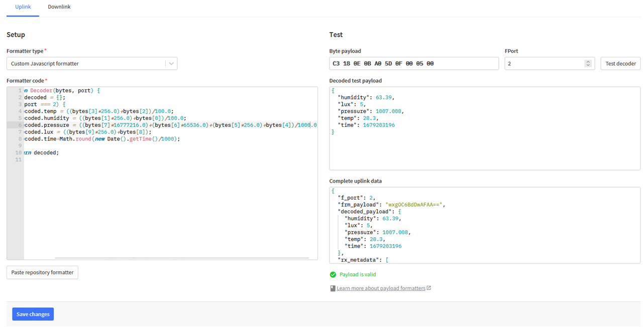
The code is listed below:
function Decoder(bytes, port) {
   var decoded = {};
   if (port === 2) {
     decoded.temp = ((bytes[3]*256.0)+bytes[2])/100.0;
     decoded.humidity = ((bytes[1]*256.0)+bytes[0])/100.0;
     decoded.pressure = ((bytes[7]*16777216.0)+(bytes[6]*65536.0)+(bytes[5]*256.0)+bytes[4])/1000.0;
     decoded.lux = ((bytes[9]*256.0)+bytes[8]);
     decoded.time=Math.round(new Date().getTime()/1000);
   }
   return decoded;
}
Now that the data is interpreted, it can be shared with other applications and parsed, however, that will be the subject for another blog.
Adding a Battery
Given the surprisingly low power usage of the board on its own, I decided to check the power consumption with the sensors connected.
Using the same two-power-supply trick, I disconnected the “bulk” supply after the RX1/RX2 windows to leave the Keithley 2450 SMU measuring the standby current. I left it long enough to see that the board browned out on attempting to restart just to make sure the board was truly in standby and not just “crashed”. Given the timing of the brownout is congruent with the settings, this suggests the standby power readings are valid.
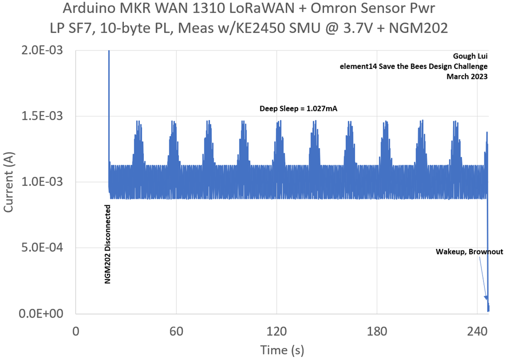
With the sensors, the deep sleep current has now increased to an average of 1.027mA. This is not ideal, but it is very good for a sensor board that has no power gating and no effort placed into power optimisation for the sensors.
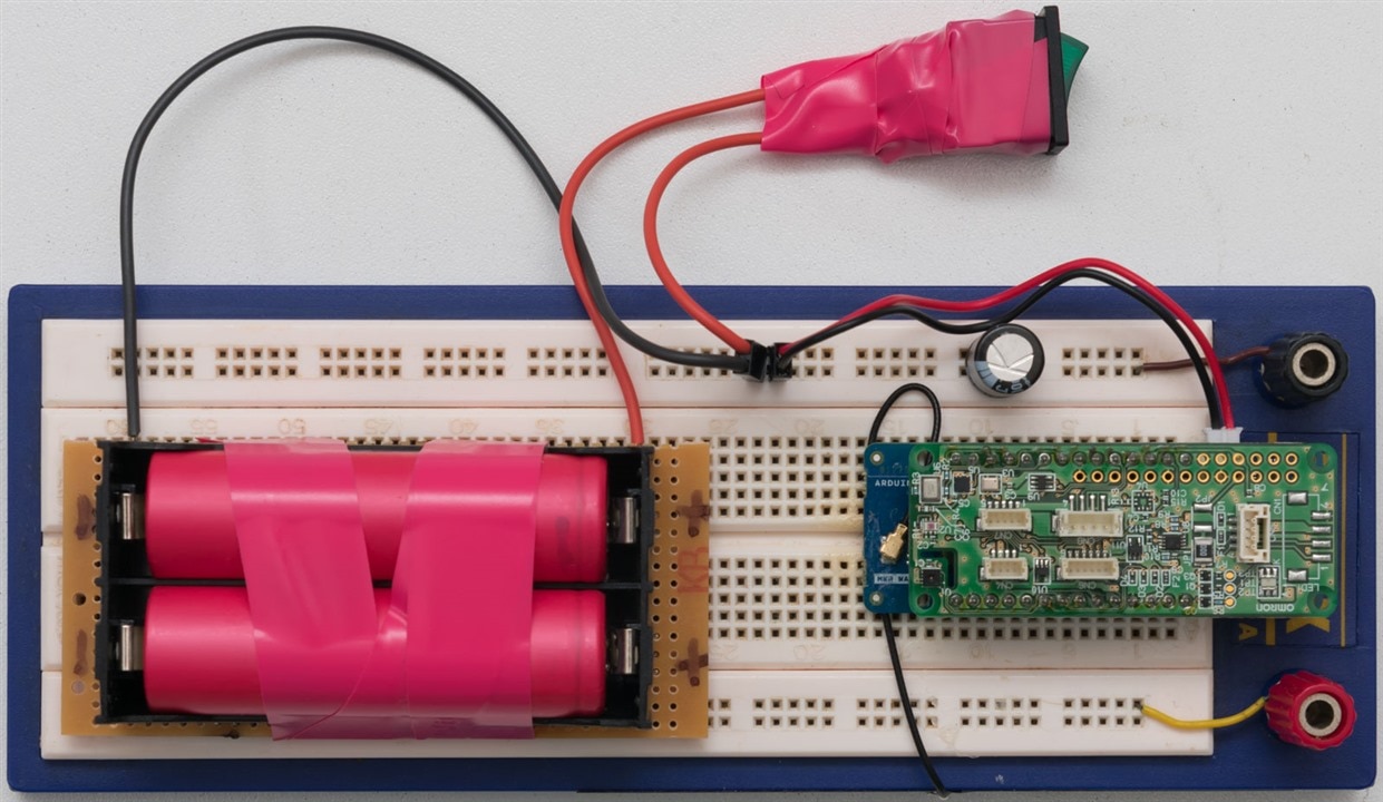
To power everything, I decided to grab an old double 18650 cell holder and pair two cells I had salvaged from an old laptop battery. Those cells have high internal resistance but a capacity that probably reaches 5000mAh combined. I charged them with my NGM202 power supply, before putting them into service.
A quick power budget calculation suggests the following:
- 125mA TX current * 30s/day fair usage = 1.0417mAh per day
- 027mA standby current * 24 hours/day = 24.648mAh per day
- Total = 25.7mAh/day
- Estimated Lifetime = 194 days (!!!)
With this result, do I really need solar power if I only need to attend to it every six months? The challenge should be over before the battery is depleted.
I crimped a few wires, added a bypass capacitor and a switch to the breadboard and it’s now finally untethered from a computer.
Unlike the MKR WAN 1300, there doesn’t seem to be an easy way to measure the battery voltage without using an external voltage divider. Unfortunately, that increases power usage, so I decided to go without, but perhaps this is another thing that a proper implementation may consider adding.
Up High, Out Wide? Can You Hear Me?
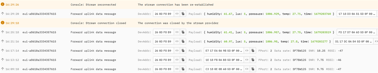
As of last post, dougw asked whether the board could be heard by other LoRaWAN gateways now that it’s running properly on AU915. I’ve hence placed the board up high and let it send packets for a while.
Looking closely at the rx_metadata in The Things Network Live Data view, you can see if duplicate versions of your packets are received by other gateways.
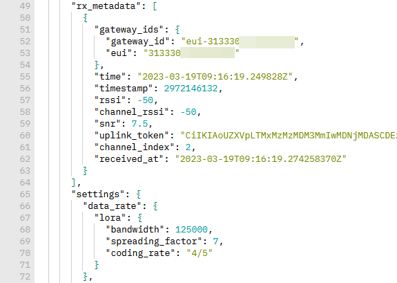
If you only see one gateway, then you’re only being heard by the one gateway. Sometimes gateways will pop in and out depending on the changing radio conditions, but for now, I don’t have reliable coverage from any of the other gateways in the “neighbourhood”. Running my own gateway still seems to be a must.
Conclusion
At last, this could be considered approaching a standalone monitoring system connected with LoRaWAN. The MKR WAN 1310 is very efficient when using the Arduino Low Power library and disabling USB, achieving just 60.4µA sleep consumption. While I have been fortunate to have a “shortcut” in the form of the Omron 2JCIE-EV01-AR1 Environmental Sensor Shield, I have been even more fortunate that it only increases sleep power consumption to 1.027mA which, while not ideal, is not difficult to provide for. Given this, a quick back-of-the-envelope suggests a pair of old 18650s could run the board for over six months between charges. This gave me a good push to get a battery into the device and get it running – after all, one can only determine stability by testing the system over time.
I was able to define a packed data format and a matching Javascript decoder to ensure the data is presented nicely. While it works, there is a subtlety with negative temperature values which are not supported at this time. Data integrations will be looked at in a future blog to take the data from The Things Network into another system.
Later on, I suppose we may still want to monitor battery state which will require an additional voltage divider (along with current consumption). Adding a way to charge the battery from solar will still be a good idea, but perhaps a small panel could be enough (although I’m not sure I’ve got a small one to hand).
But perhaps it’ll be time to get started on the Arduino Pro Nicla Vision to see just what it’s capable of. As a first-time computer-vision and artificial intelligence user, I don’t expect this part to be simple. But if I’m not able to get going with that, perhaps I’ll get going on recording and presenting environmental data instead.
[[BeeWatch Blog Index]]
- Blog 1: README.TXT
- Blog 2: Unboxing the Kit
- Blog 3: LoRa vs. LoRaWAN & Getting Started with MKR WAN 1310
- Blog 4: LoRaWAN Gateway Set-Up & MKR WAN 1310 Quirks
- Blog 5: Power, State Saving, Using Sensors & Battery
- Blog 6: Particulate Monitoring & Solar Power Input
- Blog 7: Powered by the Sun & Initial Data
- Blog 8: Getting Started with Nicla Vision
- Blog 9: Nicla Vision IR ToF & Audio Sensing, Data Dump
- Blog 10: Nicla Vision Power, Saving B’s & Dashboard Woes
- Blog 11: Summary Conclusion