element14 Community
element14 Community
    Register Log In
  • Site
  • Search
  • Log In Register
  • About Us
  • Community Hub
    Community Hub
    • What's New on element14
    • Feedback and Support
    • Benefits of Membership
    • Personal Blogs
    • Members Area
    • Achievement Levels
  • Learn
    Learn
    • Ask an Expert
    • eBooks
    • element14 presents
    • Learning Center
    • Tech Spotlight
    • STEM Academy
    • Webinars, Training and Events
    • Learning Groups
  • Technologies
    Technologies
    • 3D Printing
    • FPGA
    • Industrial Automation
    • Internet of Things
    • Power & Energy
    • Sensors
    • Technology Groups
  • Challenges & Projects
    Challenges & Projects
    • Design Challenges
    • element14 presents Projects
    • Project14
    • Arduino Projects
    • Raspberry Pi Projects
    • Project Groups
  • Products
    Products
    • Arduino
    • Avnet Boards Community
    • Dev Tools
    • Manufacturers
    • Multicomp Pro
    • Product Groups
    • Raspberry Pi
    • RoadTests & Reviews
  • Store
    Store
    • Visit Your Store
    • Choose another store...
      • Europe
      •  Austria (German)
      •  Belgium (Dutch, French)
      •  Bulgaria (Bulgarian)
      •  Czech Republic (Czech)
      •  Denmark (Danish)
      •  Estonia (Estonian)
      •  Finland (Finnish)
      •  France (French)
      •  Germany (German)
      •  Hungary (Hungarian)
      •  Ireland
      •  Israel
      •  Italy (Italian)
      •  Latvia (Latvian)
      •  
      •  Lithuania (Lithuanian)
      •  Netherlands (Dutch)
      •  Norway (Norwegian)
      •  Poland (Polish)
      •  Portugal (Portuguese)
      •  Romania (Romanian)
      •  Russia (Russian)
      •  Slovakia (Slovak)
      •  Slovenia (Slovenian)
      •  Spain (Spanish)
      •  Sweden (Swedish)
      •  Switzerland(German, French)
      •  Turkey (Turkish)
      •  United Kingdom
      • Asia Pacific
      •  Australia
      •  China
      •  Hong Kong
      •  India
      •  Korea (Korean)
      •  Malaysia
      •  New Zealand
      •  Philippines
      •  Singapore
      •  Taiwan
      •  Thailand (Thai)
      • Americas
      •  Brazil (Portuguese)
      •  Canada
      •  Mexico (Spanish)
      •  United States
      Can't find the country/region you're looking for? Visit our export site or find a local distributor.
  • Translate
  • Profile
  • Settings
Safe and Sound
  • Challenges & Projects
  • Design Challenges
  • Safe and Sound
  • More
  • Cancel
Safe and Sound
Blog MSP432 and TI-RTOS: PID Library Part 1 - Intro
  • Blog
  • Forum
  • Documents
  • Polls
  • Files
  • Events
  • Mentions
  • Sub-Groups
  • Tags
  • More
  • Cancel
  • New
  • Share
  • More
  • Cancel
Group Actions
  • Group RSS
  • More
  • Cancel
Engagement
  • Author Author: Jan Cumps
  • Date Created: 22 Jan 2017 1:02 PM Date Created
  • Views 2510 views
  • Likes 10 likes
  • Comments 10 comments
  • safe and sound
  • msp432
  • pid
  • arduino
  • launchpad
  • ti_rt
Related
Recommended

MSP432 and TI-RTOS: PID Library Part 1 - Intro

Jan Cumps
Jan Cumps
22 Jan 2017

A port of the very good Arduino PID library to  MSP432 LaunchPad and TI-RTOS.


image

image source: e2e.ti.com

PID is a control algorithm. It tries to keep the output of a device at a desired level by controlling its input.

Part 1 describes the port from Arduino C++ to C.


What you need:

  • MSP432 LaunchPad
  • 1 micro-USB cable
  • Code Composer Studio
  • TI-RTOS for MSP43X


Why a PID Library?

When you build a power supply, you want to set the output voltage to a fixed level. And you want to keep it at that level, whatever happens.

When the user connects a heavy load, this shouldn't affect the output.

To get that working, you need to change the input signals to the circuit.

But how do you do that? How much change? How fast? How to prevent that the change pushes the output above the level?

And what if the load is removed?

That's a problem that the PID mechanism tries to resolve:

a stable control of the output, by measuring the difference with the desired output (error), using other factors (such as history) and changing the input signal (feedback) until balance is achieved.

The difference between the desired output and the actual current value is called the error.

P stands for proportional, I for Integral, D for differential. These are the mathematical terms that play a role in the calculations inside the PID library.


Why *This* Library?

Because it's based on a good one. It's an as true as possible port of Brett Beauregard's Arduino PID Library.

Because it has Tuning options.

Because it is extremely well documented. You should (really: should) read Brett's blog before continuing here: Improving the Beginner’s PID – Introduction « Project Blog.


Port for MSP432

It's not really for the MSP432, it's for any application that's in C. But I'm working on a MSP432 controlled project that needs PID.


That project is the reason why I've made the MSP432 blog series: a real world problem that needs to be solved, and me not knowing the MSP432 at all when starting it.

Each post in the series is documentation for one of the aspects that I had to master..


As an object oriented design aficionado, I prefer to migrate C code to C++. In this case it's the other way around.


What's different from the Arduino lib?

We loose something along the road. Not encapsulation, because I try to expose only public functionality.

But with Brett's OO library, you can have multiple PID objects. That's useful when your instrument has to support different operating modi (e.g.: a power supply with either constant voltage or constant current).

With the Arduino library, you can create two objects, each with their own PID values. That doesn't work yet with my port.

I'm planning to add similar functionality in a later release. I need that myself.


The PID() constructor is replaced by an init function


void pidInit(double*, double*, double*, double, double, double, int)


Public constants are prefixed with "PID_"


  #define PID_AUTOMATIC 1
  #define PID_MANUAL    0
  #define PID_DIRECT  0
  #define PID_REVERSE  1


Public functions are prefixed with "pid"


    void pidInit(double*, double*, double*, double, double, double, int)
    void pidSetMode(int Mode)
    bool pidCompute()
    void pidSetOutputLimits(double, double)

    void pidSetTunings(double, double, double)
    void pidSetControllerDirection(int)
    void pidSetSampleTime(int)

    double pidGetKp()
    double pidGetKi()
    double pidGetKd()
    int pidGetMode()
    int pidGetDirection()


The Arduino millis() function internals are replaced with a TI-RTOS portable time function. This is private within the library.


    long millis() {
        long t = Timestamp_get32();
        long msecs = (t & 0x7fff) * 1000 /32768;
        return msecs;
    }


In your TI-RTOS project, you have to add this line of code to the very end of your .cfg file -  (double-click the file and then press the cfg Script tab at the bottom of the editor window):


/* ================ Application Specific Instances ================ */
var TimestampProvider = xdc.useModule('xdc.runtime.Timestamp');


The comment line is already in that file. Paste the line of code underneath it.

If you want to use this port in a non-TI-RTOS project, you'll have to build your own implementation of millis().


How is it used in an TI-RTOS project?

I'm not sure about that yet. My current project will hopefully show the right way to do it.

My current approach is to have an RTOS task schedule. The PID library prefers that the control loop runs at regular intervals.


#include "pid.h"

//Define Variables we'll be connecting to
double Setpoint, Input, Output;

/*
 *  ======== fnTaskPID ========
 *
 */
Void fnTaskPID(UArg arg0, UArg arg1)
{

    //Specify the links and initial tuning parameters
    double Kp=2, Ki=5, Kd=1; // todo make these good values for our strategy
    Setpoint = 0.0;
    pidSetSampleTime(((UInt)arg0) / Clock_tickPeriod);
    pidSetOutputLimits(0, 255);
    Input = 0.0; // 
    pidInit(&Input, &Output, &Setpoint, Kp, Ki, Kd, PID_DIRECT);

     //turn the PID on
     pidSetMode(PID_AUTOMATIC);

    while (1) {
        Task_sleep(((UInt)arg0) / Clock_tickPeriod);
    //      Input = analogRead(PIN_INPUT); todo: sample your device actual output value
            if (pidCompute()) {
              System_printf("setpoint = %f ; input = %f ; output =%f \n", Setpoint, Input, Output);
              System_flush();
    //        analogWrite(PIN_OUTPUT, Output);   todo: set your device input to this value. 
            }
    }
}


The default output range is 255. That may be rough for some situations. The bigger you set this value, the more steps the library can use.

It makes sense to define this relative to the method you're using to drive your instrument's input.

If you're using a 32-bit PWM module, you could use:


     pidSetOutputLimits(0, UINT32_MAX);


For a 14-bit DAC, you could set it to:


     pidSetOutputLimits(0, 0b11111111111111);


Side note: logging double values in the TI-RTOS console:


By default, TI-RTOS doesn't compile the code to format %f in the System_prinf() function.

RTSC considers the %f an 'extended format' which is not compiled in by default.


Add the following line to the end of the TI-RTOS  .cfg file:


System.extendedFormats = '%$L%$S%$F%f';


You can register the task in source code (as done in the TI-RTOS empty example) or by setting it up in the TI-RTOS configuration editor (check here for instructions).

image

Choose the sleep time based on the requirements of your control process. The 1000 ms that I've put here are arbitrary. You may want to adjust your process faster or less frequent.

If you use the task code above, the PID library's sample time will automatically be initialised to the timeout you define in Argument 0.

This line of code takes care of that:

pidSetSampleTime(((UInt)arg0) / Clock_tickPeriod);


Don't forget to register the TimestampProvider in the .cfg file, as explained above.


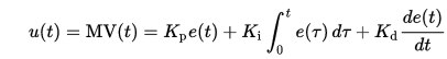
Side note: Algorithm


The core algorithm of the library is a pure implementation of the PID theory:


          /*Compute all the working error variables*/
          double input = *myInput;
          double error = *mySetpoint - input;
          ITerm+= (ki * error);
          if(ITerm > outMax) ITerm= outMax;
          else if(ITerm < outMin) ITerm= outMin;
          double dInput = (input - lastInput);


          /*Compute PID Output*/
          double output = kp * error + ITerm- kd * dInput;


          if(output > outMax) output = outMax;
          else if(output < outMin) output = outMin;
          *myOutput = output;


          /*Remember some variables for next time*/
          lastInput = input;
          lastTime = now;


image

image source: wikipedia


As you can see, my PID is WIP. The ported code is attached to this blog post as a zip archive.

(for the TM4C123GXL lovers, there's a full CCS project attached to this blog )

Have fun. Tell me if anything isn't OK please.


TI-RTOS Series
MSP432 and TI-RTOS: Getting Started Pt. 1 - Set Up and 1st RTOS Task
MSP432 and TI-RTOS: Getting Started Pt. 2 - Add an ADC Sample Task
MSP432 and TI-RTOS: Getting Started Pt. 3 - USB with Minimal CPU Use
MSP432 and TI-RTOS: PWM
MSP432 and TI-RTOS: I2C Configuration for Sensors BoosterPack
MSP432 and TI-RTOS: another I2C example - talk to a DAC
MSP432 and TI-RTOS: Sharp LCD BoosterPack
MSP432 and TI-RTOS: PID Library Part 1 - Intro
MSP432 and TI-RTOS: PID Library Part 2 - Real World Example
Attachments:
pid_lib.zip
TM4C_PID_TIRTOS_EK_TM4C123GXL_TI.zip
  • Sign in to reply

Top Comments

  • fmilburn
    fmilburn over 8 years ago +3
    Jan, I have worked my way through your examples up to here and they are great! I did skip the one on DACs because I don't have that part but it was easy to follow. Regarding your comment on this particular…
  • Jan Cumps
    Jan Cumps over 8 years ago +2
    This part of the blog series is also a good excuse to try out the LED board that jc2048 gave me (I've gone medieval on the PSU ). I'm going to train myself on the internals of the LIB with that. (I took…
  • DAB
    DAB over 8 years ago +2
    Nice post Jan. It reminds me of some of the control algorithms I developed in the mid 1980's to control a FLIR device and slave it to the movement of a helicopter. I had to constantly update the FLIR look…
Parents
  • Jan Cumps
    Jan Cumps over 8 years ago

    This part of the blog series is also a good excuse to try out the LED board that jc2048 gave me (I've gone medieval on the PSU image ). I'm going to train myself on the internals of the LIB with that.

    (I took a specialisation year on control theory in 1985-86, but I've forgotten more than 100% of it)


    image


    The project that I'm going to control with the PID lib has i2c as input and output. This board has analog out and PWM at the input.

    That will force me to keep the lib independent of the device and have it as a reusable entity, as intended by the original creator).


    Also because it has 3 controllable circuits, I can use it to extend the library to support more than 1 control strategy, and see if I can switch between them.

    • Cancel
    • Vote Up +2 Vote Down
    • Sign in to reply
    • More
    • Cancel
  • jc2048
    jc2048 over 8 years ago in reply to Jan Cumps

    If I wanted to have a go with the PID code, and it does sound interesting, would I be able to get it running easily on a EK-TM4C123GXL evaluation board? I bought it a while back as a way to learn about ARM processors, but haven't done anything with it to date. It's got a 80MHz M4 with 256k Flash and 32K SRAM (hopefully that will mean more to you than me, you being something of an expert on all things TI).

    • Cancel
    • Vote Up 0 Vote Down
    • Sign in to reply
    • More
    • Cancel
  • Jan Cumps
    Jan Cumps over 8 years ago in reply to jc2048

    The TM4C should be able to run this - this library is tiny and your controller is more powerful than the MSP432 on all levels (edit : not the RAM, my controller has 64KB).

    If you start with a TI-RTOS project, add this line to the end of your .cfg file in the root of your project.

    (I should add that to the main explanation)


    var TimestampProvider = xdc.useModule('xdc.runtime.Timestamp');


    I have tried to develop for RTOS as controller-independent as possible.

    If you plan to use a bare metal project, you'll have to implement your own millis() implementation


    Here's the size in bytes with debug enabled:


           Module                     code    ro data   rw data
           ------                     ----    -------   -------
        .\pid\pid_lib\
           pid.obj                    1374    0         105    
        +--+--------------------------+-------+---------+---------+
           Total:                     1374    0         105   

    • Cancel
    • Vote Up +1 Vote Down
    • Sign in to reply
    • More
    • Cancel
  • Jan Cumps
    Jan Cumps over 8 years ago in reply to jc2048

    jc2048, I've tested on a TM4C129EXL, that works.

    For your LaunchPad, the EK_TM4C123GXL, I've created and compiled the project.

    It's attached here. Warning: untested, I don't have that controller.


    You'll need: Code Composer Studio 7 (during installation, take care to select the TM4C/TIVA controller).

    Then, from View -> Resource Explorer, download TI-RTOS for Tiva.

    Then restart CCS.

    Then import the zip file via Project -> Import CCS project.


    Set a breakpoint in ./pid/pid_impl.c

    line         

    if (pidCompute() ) {


    It should be called by the OS every second.

    • Cancel
    • Vote Up +1 Vote Down
    • Sign in to reply
    • More
    • Cancel
  • jc2048
    jc2048 over 8 years ago in reply to Jan Cumps

    Thanks Jan, that's very helpful.


    I'm working on a couple of transistor blogs at the moment, but when they're done I'll give it a go and then I can see how I get on tuning a PID loop.

    • Cancel
    • Vote Up 0 Vote Down
    • Sign in to reply
    • More
    • Cancel
Comment
  • jc2048
    jc2048 over 8 years ago in reply to Jan Cumps

    Thanks Jan, that's very helpful.


    I'm working on a couple of transistor blogs at the moment, but when they're done I'll give it a go and then I can see how I get on tuning a PID loop.

    • Cancel
    • Vote Up 0 Vote Down
    • Sign in to reply
    • More
    • Cancel
Children
No Data
element14 Community

element14 is the first online community specifically for engineers. Connect with your peers and get expert answers to your questions.

  • Members
  • Learn
  • Technologies
  • Challenges & Projects
  • Products
  • Store
  • About Us
  • Feedback & Support
  • FAQs
  • Terms of Use
  • Privacy Policy
  • Legal and Copyright Notices
  • Sitemap
  • Cookies

An Avnet Company © 2025 Premier Farnell Limited. All Rights Reserved.

Premier Farnell Ltd, registered in England and Wales (no 00876412), registered office: Farnell House, Forge Lane, Leeds LS12 2NE.

ICP 备案号 10220084.

Follow element14

  • X
  • Facebook
  • linkedin
  • YouTube