
Welcome to the Panasonic Industry page on element14. Here you can find things such as our latest news, training videos, and product details. Additionally, you can engage with us in our forums.
...that the demand for Multilayer Ceramic Chip Capacitors (MLCCs) is growing: Applications in the field of consumer electronics, data processing, telecommunications and many others have not only significantly intensified MLCC market growth – they even led to an industry-wide shortage for the recent years.
All those parameters contributed to more and more OEMs started looking for alternatives to eventually replace MLCCs with different capacitors – also in anticipation of an increasing demand due to 5G.
Some relevant MLCC alternative can be found within Panasonic Industry’s portfolio: As leading manufacturer of Polymer Capacitors with a long design-in expertise, the SP-Caps and OS-CON are as well worth a closer look as POS-CAP Tantalum Polymer Capacitors or the manufacturer’s Polymer Hybrid Aluminum Electrolytic Capacitor technologies.
For conductive Polymer capacitors, the fields of application have remarkably broadened. The Polymer capacitor (as well as conventional aluminum electrolytic capacitors) stands out with large capacitance figures and excellent bias characteristics that are clearly outperforming multilayer ceramic capacitors.
Panasonic Industry Polymer capacitors already have been proven as a highly relevant alternative for customers seeking to save PCB space and money.
Those Polymer-based capacitors offer a performance edge over conventional electrolytic and ceramic capacitors when it comes to:
• Electrical characteristics
• Stability
• Longevity
• Reliability
• Safety
• Life cycle cost
The various Polymer and hybrid capacitors have very specific advantages and benefits in terms of their ideal voltages, Low ESR, operational conditions and other application requirements.
Including the hybrid ones, there are basically four main varieties of Polymer capacitors. Each of them comprises different construction, electrolytic and electrode materials, packag¬ing and application targets. Let us have a brief overview:
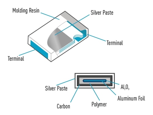
Using a conductive Polymer as the electrolyte and an aluminum cathode, the distinguishing electrical characteristic of these Polymer capacitors is their extremely low equivalent series resis¬tance (down to 3mΩ), which is among the lowest in the industry. SP-caps cover a voltage range from 2–6.3V and offer capacitances between 2.2–820μF. Packaged in a molded resin as compact SMD, these layered Polymer capacitors come in a low pro¬file. As a result of the electrical and form factor characteristics, they suit a variety of handheld electronic devices or other applications that require a low-profile capacitor that will not interfere with a nearby heat sink.
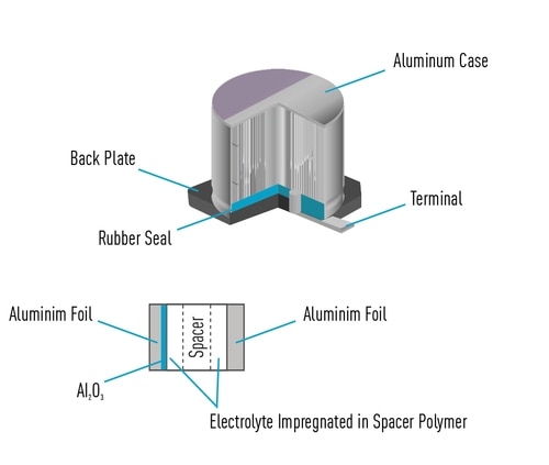
OS-CON caps are also based on conductive Polymers and aluminum, but they have a wound foil structure. The wound Polymer capacitors cover a wider range of voltages and capacitance values than other types of Polymer capacitors. Voltages extend from 2.5 to 100V, while capacitances run from 3.3 to 2,700μF. In addition, their long life time span is one of the factors that they are preferred to be used for servers and base stations. For example, SVPT series with 20,000 hours of life time at 105°C is a unique solution for such applications.
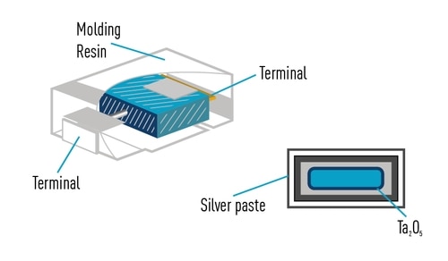
These types employ a conductive Polymer as the electrolyte and have a tantalum cathode. They span voltages from 2 to 35V and capacitances from 3.9 to 1,500μF. They also convince with a low ESR, with some of our POSCAP capacitors exhibiting ESR values as low as 5mΩ. Packaged in a molded resin case, the tantalum Polymer capacitors are among the most compact options available on the market. Though compact, a wide range of sizes is available for this capacitor type.
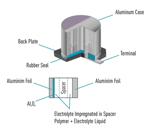
Hybrid capacitors consist of a combination of a liquid and conductive Polymer to serve as the electrolyte and aluminum as the cathode. The Polymer offers high conductivity – and a correspond¬ingly low ESR. The liquid portion of the electrolyte, meanwhile, can withstand high voltages and provide higher capacitance rat¬ings due to its large effective surface area. The hybrid capacitors offer a voltage range from 25 to 80V and capacitances between 10 and 1000μF. At 8 to 120mΩ, ESR values for hybrids are higher than other types of Polymer capacitors, but still very low considering the higher power applications they address.
It's not only the industry-wide MLCC shortage: Panasonic Industry Polymer caps stand out with excellent specs and characteristics that makes them outperform conventional MLCCs ion several regards.
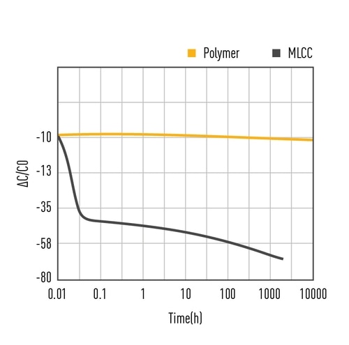
The MLCC exhibits strong capacitance dependence on DC bias due to ferroelectric dielectric materials used for MLCCs. Polymer ca¬pacitors have no such problem and remain stable over time. This specific advantage allows a significantly lower part count using Polymer instead of MLCCs – apparently saving precious PCB space, costs and steps during production process.
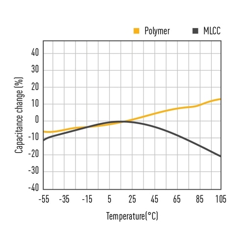
This figure illustrates typical temperature characteristics. The curve changes for MLCCs in various ways within the tolerance range of each product. For Polymer capacitors the capacitance is growing in parallel to the increase of temperature. The temperature characteristics of MLCCs differ according to the dielectric type, but all of them suffer aging failure by exhibiting temperature dependency and require lower operating temperature. Ceramic capacitors are brittle and sensitive to thermal shock, so precautions need to be taken to avoid cracking during mounting, especially for high-capacitance large MLCCs. Typically, ceramic capacitors reveal a temperature range from -40°C to 85°C, respectively 125°C, while the capacitance varies about from +5% to -40%, being in the optimal range around a low temperature of 5 to 25°C. Also in terms of density, field stress and temperature – which is currently still limited to 125°C – Polymer capacitors have great development potential to achieve higher ratings on density, field stress and temperature (yet currently limited to 125°C) due to their working mechanism and dielectric materials advancement, yet higher dielectric constant Polymers enable a higher energy density.
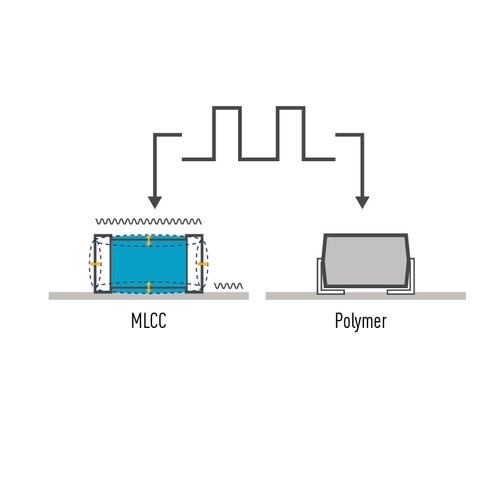
A MLCC deforms – meaning contraction or expansion - when exposed to voltage. This MLCC's characteristic is called inverse piezoelectric effect - the reverse of a piezoelectric effect. A DC voltage output from an AC adaptor or switching power supply causes a ripple voltage in some cases. If the frequency of the ripple voltage is within the audible frequency range, it may result in emission of a screeching noise. A conductive Polymer capacitor has no inverse piezoelectric effect and therefore does not cause any noise emission or micro-vibrations.
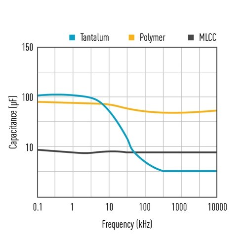
Stable Capacitance: The figure on the left shows the change in capacitance over a wide frequency range for different technologies. It clearly shows that Polymer capacitors exhibit very similar performance to multi-layer ceramic capacitors.

Cracks in ceramic surface mount technology (SMT) components limit assembly reliability and yields. These cracks manifest themselves as electrical defects: intermittent contact, variable resistance, loss of capacitance and excessive leakage currents. That is why MLCCs are exposed to different reliability tests including thermal shock, board flex (bending), and biased humidity tests, etc., depending on the targeted applications. Among the reliability tests, the board flex test evaluates the mechanical resistance to cracking when MLCCs are subjected to bending stress on the printed circuit board (PCB) that the MLCC is soldered on. The bending of PCB can occur frequently during/between manufacturing steps and during operation under temperature variations. Flex cracking is due to excessive circuit board flexure. Ceramics are strong in compression but weak in tension. Thus, when a soldered MLCC experiences excessive board flex, a crack is easily generated in the element. A flex crack can cause an electrical conduction between opposing internal electrodes. It is also possible that a fail open can progress to a fail short with continued product usage. If a crack on a capacitor element progresses to a short circuit failure, it may cause problems such as heat generation, smoking, or ignition; therefore, it is indispensable to take measures against them, particularly in equipment where reliability is essential.
Most ceramic capacitors have a fairly high voltage rating. If the capacitor experiences a voltage between its terminals higher than its rated voltage, the dielectric may break down and electrons will flow between the thin metal layers inside of the capacitor, creating a short. Luckily, most ceramic capacitors are built with a hefty safety margin and do not experience any sort of catastrophic failure (such as exploding). However, the rule of thumb dictates that you should derate ceramic capacitors by 50% to 90% depending upon series, voltage and temperature, which means that if you are expecting to have a maximum of 5V between the capacitor’s leads, then you should use a capacitor rated for 10V or more. On the other hand, no derating needs to be considered for Polymer capacitors and normally they can withstand 15-25% surge voltage as well.
The range of Polymer caps as MLCC alternatives is various and comprehensive – there are specific types for specific requirements. What they all have in common, however, is that they are a contemporary choice in terms of electrical performance, reliability, durability and safety - and not least when looking at the overall lifetime cost.
Or to put it even more simply: Polymer caps are not only a good alternative in case of supply shortages of other products, but are actually the first choice for the design process of modern applications.
The increasing requirement of performance of automotive devices leads to higher electric current flowing trough electric circuits. Also the number of ECUs mounted on vehicles is gradually increasing. As space inside vehicles is limited, ECU boards must be downsized. Therefore it is essential for electronic components mounted on such boards that they are able to pass large currents and also meet downsizing requirements. Unfortunately large current type inductors are usually designed with through hole mounting type with large product sizes, which are not suitable for downsizing. Furthermore, a large range of passive components such as resistors and capacitors are surface-mounted, but this process cannot be simultaneously performed with through hole mounting. Therefore two board mounting processes are required. To solve this issue for automotive customers, Panasonic developed a power inductor which can be surface mounted and is capable of passing currents as large as 87A.
3 Features of ETQP8M***J** & ETQPAM***JFW series:
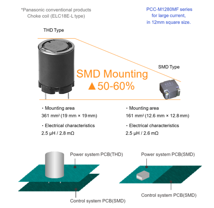


In contrast to conventional ferrite inductors, the magnetic metal composite material and the wired coil enable a gapless monolithic structure of the ETQP series. The result is a power inductor which has much lower heat generation due to reduced coil heat generation and increased coil heat dissipation. This way it was possible to enable large currents of 20A to 87A at a volume reduction of up to 50% compared to the ferrite type.


Heat resistance of 160°C is achieved by working on the composition of metal composite material. In addition, while the thick copper wire of the coil is drawn out to be used as terminals, an unique structure is adopted by fixing the terminals on the metal composite material body in a caulking structure on the bottom side, thus the vibration resistance is enhanced.

By adopting a metal composite suitable for downsizing, the company achieved a smaller inductor size with a similar performance for ferrite type inductors, which makes it possible to reducing the installation area, reduce the size of equipment, and reduce the number of materials used. It is possible to reduce the environmental load.

Unique terminal structure technology to assure heat capacity as SMD type, with the copper wire of the coil drawn out to be used as terminals.
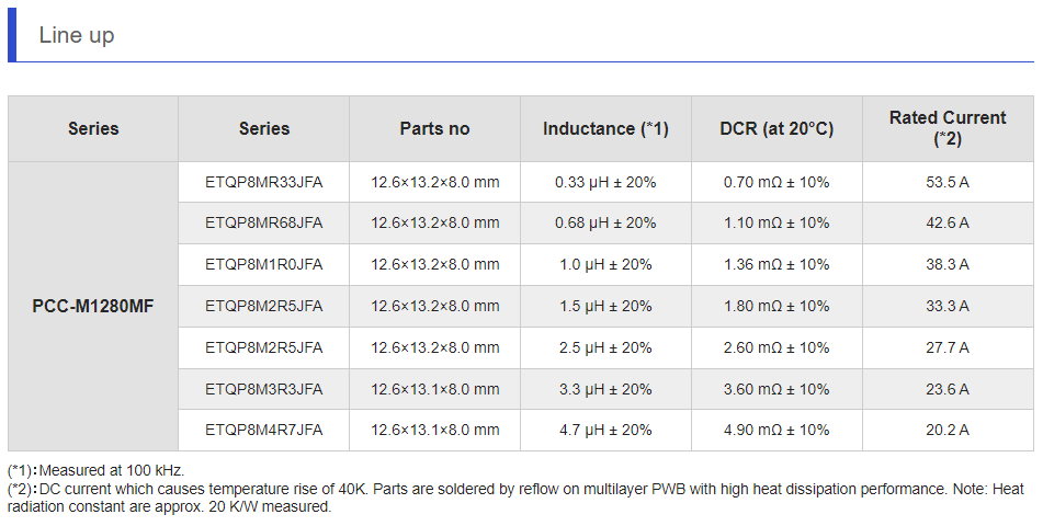
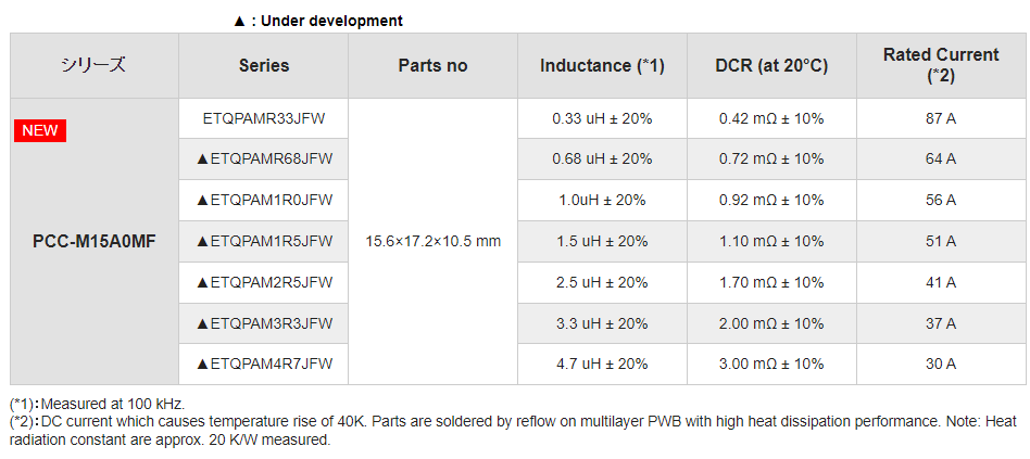
Fore more information, visit: Automotive power inductors | Panasonic Industry Europe GmbH
Panasonic Power Inductors are specifically designed for harsh environmental conditions in engine, transmission, braking systems and powertrain applications. The target was from the beginning to develop a product that is very resistant to vibration and temperature. The result was the ETQP Series, which achieved this goal and set a new quality standard for automotive metal composite power inductors. As for vibration resistance we already gave deeper insights, this time we want to focus on temperature resistance of the Panasonic ETQP Series. As there is an increased number of applications which require a maximum temperature resistance of 180°C, there are also Power Inductors introduced to the market which state a temperature resistance of up to 180°C. But what does actually stand behind such a specification with the unclear definition of up to?

To understand the impact of temperature on a power inductor we first want to take a look at the components and materials which the ETQP series is made up. The core consists of metal composite powder which is bound by a proprietary heat resistant binder system. The metal core material has a curie temperature of over 500°C, the core binder material has a heat resistance of over 200°C. The wire wound coil inside which is placed inside the core has a high quality amide imide wire coating material which is heat resistant over 200°C. All components were deliberately chosen with highest quality available in the market.
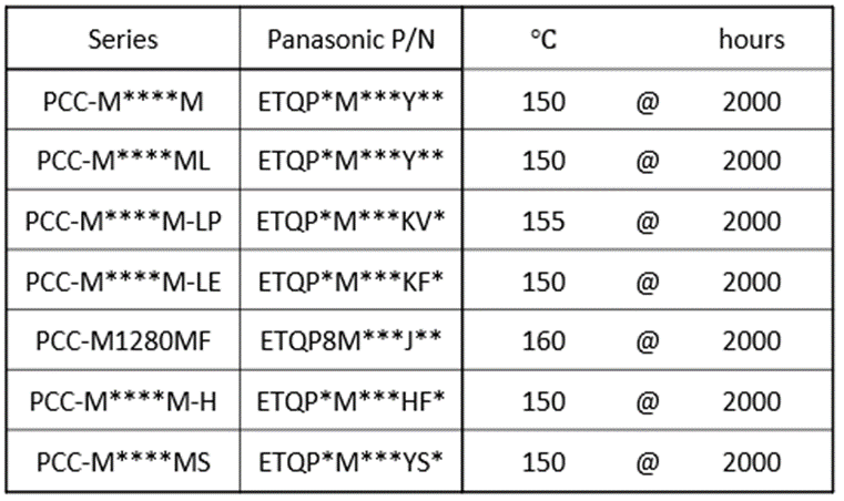
After the detailed explanation of the temperature robustness of each single component we can take a look at the temperatures of the standard endurance specification. The table below shows the specified temperature resistance of 150°C, 155°C and 160°C for a duration of 2000 hours, depending on the series.
But that does not automatically mean that the power inductor is being destroyed when the specified temperature is exceeded. In fact each ETQP Power Inductor can handle even 180°C for a certain period of the specified lifetime. But this extraordinary temperature stress has an negative impact on the total lifetime which can be guaranteed for the product. This impact can be calculated by the Arrhenius formula and life time temperature profile, which we want to take a deeper look at now.
The following graph shows the relationship between lifetime and temperature stress of an ETQP inductor which has a specified temperature of 150°C. It shows an example of an application profile which exceeds the specified temperature by 30°C for 10 hours of its lifetime. The impact can be calculated with help of the Arrhenius formula. In case of this scenario, the guaranteed product lifetime of 2000 hours is being reduced to only 1750 hours at 150°C plus 10 hours at maximum 180°C. Than it has to be looked into the required overall lifetime of the power inductor to evaluate if the remaining lifetime still matches the requirements of the application.

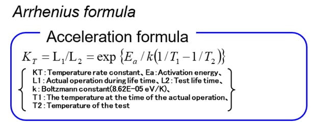
As with many other data in the specification sheet of a power inductor, there has to be a deeper look behind what is presented at first sight. Even if a temperature resistance of 180°C is declared, it is not clear for how long the product can resist this temperature and what is the impact on the overall lifetime of the component. Panasonic intentionally does not state a temperature resistance of up to 180°C of the ETQP Series, as this information would be misleading without a deeper look into the overall temperature profile of the target application. However due to the high quality materials and design of the product, it definitely can be used for applications which require a temperature resistance of up to 180°C for a limited period of time. The product engineers from Panasonic will be happy to help you with detailed information and guidance if you need support in such a case.
To learn more, please visit our website:
When Panasonic started the development of the first metal composite power inductor nearly two decades ago, the key target was to design a product that would be able to withstand severe conditions and provide the highest reliability for automotive applications.
Nowadays, Automotive engineering witnesses almost dizzying progress in electrification. Correspondingly, the demand for passive components such as coils reliably withstanding harsh automotive conditions is higher than ever before. And it’s not only about constructive toughness and heat resistance: At the same time, there is a clear trend towards ever smaller components to save space and reduce weight.
With the introduction of the ETQP-series, those requirements were not only met, but in many cases even exceeded. In the following, we will briefly spotlight those key design elements that substantiated the PCC’s excellent reputation in many fields of applications:

Back then, when the development of the first metal composite inductors started, power inductors were basically all made of ferrite. This type of inductor consists of several sintered parts which are combined and come with an air gap inside the body. Due to its assembled structure, the resistance to vibrations of ferrite inductors is limited from <4G to a maximum of 10G.
In contrast, the Panasonic Industry metal composite power inductor has a monolithic design by pressed metal powder around the copper wire. The monolithic structure leads to a much higher vibration resistance, up to 30G - depending on the series.

Another important feature that guarantees the highest reliability is the terminal design. The gap structure between the backside of the terminal and the core minimizes solder joint crack issues caused by thermal stress. Furthermore, a unique terminal structure without an internal joint ensures superior vibration resistance. The ETQP_M___Y__ - series leads the copper wire from the inside core to the bottom of the outer terminal, enabling a direct connection to the PCB and safeguarding the highest mechanical joint solder connection stability.
As temperature requirements are getting more and more demanding in automotive and other customer applications - not least because the component density in modern vehicles is increasing more and more - it is crucial that a power inductor can withstand high temperatures over a long lifespan. Depending on the type, the ETQP series is specified for operation up to 160 °C including self-heating. This is possible because no adhesives are used in the design, which is typically a weak spot for temperature resistance. The resin material of the core itself as well as the coating of the copper wire have a heat resistance of over 200°C.

Although the standard ETQP types already offer a very high vibration resistance, there are some applications that require an even higher specification, for example, PCBs which are mounted directly on a motor or powertrain. Panasonic Industry tackled this challenge and developed the ETQP_M___YS_ series, ensuring resistance to vibrations of up to 50G. This has been made possible by lowering the centre of gravity with a change in the terminal structure – so this series is ready to use in even the most demanding environments.
In summary, with the ETQP-series, Panasonic Industry created a power inductor whose monolithic structure of the metal composite core in combination with the terminal design and thermal robustness leads to a product with the highest reliability for even the most demanding automotive, high temperature, high vibration applications, throughout the lifespan of a modern vehicle.
Admittedly, Wi-Fi technology is not the latest thing – but it’s still state of the art when it comes to processing higher data rates, especially in personal area networks.
Now, Panasonic Industry is breaking new ground with its new PAN9520 wireless module. Containing the ESP32-S2 chip, it can be considered as the first Espressif-based module that enables standalone Wi-Fi applications.
The PAN9520 is part of a new generation of Panasonic Industry’s evolution boards coming with the Arduino form factor, serving the trend for mass-market available shields with the mere purpose of rapid prototyping.
Surveillance cameras, for instance, still are a domain of Wi-Fi networks, so let’s look exemplarily at the Arduino PAN9520 evaluation board and its interaction with the OV2640 camera – from the required hardware and toolchain to finally running the demo. So join us for this step by step instruction:
Chip | ESP32-S2 |
|---|---|
Performance | Up to 240 MHz |
Technology | 2.4 GHz Wi-Fi 802.11 b/g/n |
Memory (internal) | 128kB ROM, 320kB SRAM, 16kB low power SRAM |
Memory (additional external ) | 4MB Flash, 2MB PSRAM or MB Flash, 0MB PSRAM |
Security features | WPA2 and WPA3 personal |
Figure 1. The Panasonic Industry PAN9520 is a 2.4 GHz 802.11 b/g/n embedded Wi‑Fi module based on Espressif ESP32-S2 that includes the powerful Xtensa 32-bit LX7 CPU.
Figure 2. OV2640 Camera Module with flexible PCB connector (like this one)
The project has been developed in Visual Studio Code (VS Code). Thanks to its cross-platform compatibility, the code can be built and adapted on all operating systems.
You are required to take two simple steps:
1. Install Visual Studio Code (here)
2. Install PlatformIO Extension over the VS-Code extension menu and wait for the installation to finish, this might take a while.

git clone –recursive https://github.com/panasonic-industry-europe/pan9520-etu-camera-stream-web-server.git
Or by going directly to the GitHub repository https://github.com/panasonic-industry-europe/pan9520-etu-camera-stream-web-server.git and download the Code directly from there.
4. Go to "File" -> "Open Folder" and select the project folder containing this application. Wait for all the dependencies to be downloaded and installed automatically.
Basically, the code works out of the box. However, it is important to know where to change the settings for the softAP, e.g. to change the password or the SSID.
main.c
In the main.c file, the initialize_cam function is used to configure and initialize the hardware to ensure that the camera works properly (lines 38-61). These settings were made for the OV2640. In principle, it is possible to connect other cameras if the pinout is similar. In the main function app_main, the previously mentioned initialization of the camera is started alongside the WiFi access point and the webserver.
httpd.c
In the httpd.c file the settings are configured for the webserver. The setup for the webserver is done in the app_httpd_main function, where two URI handlers are being registered: the index_handler for the static Html output and the stream_handler which streams the camera image continuously.
What you end up seeing in the browser is set in the index_handler (line 45-73). A simple static text "PAN9520 ETU Cam live stream" (line 60) alongside the continuous camera stream in a small box below the text (line 61) which is being delivered by the stream_handler (line 76-139). If you analyze the code more closely, it becomes clear that the image is loaded from the framebuffer (line95-100) continuously and sent in fragments so-called chunks (line 101-127). A calculation of the framerate is displayed in the logging (line 128-137).
Wifi.c
The settings of the WiFi connection are made in the wifi.c file. The Access Point configuration like the SSID name or maximum numbers of connections is set in lines 30-34. The event handling for Wifi is handled in the wifi_event_handler function (line 39-58), for the sake of simplicity, this function will not be discussed further in detail. It is only important to know that there are basically two states from the handler's point of view: that of a connected and disconnected client.
The most important settings and initializations of the access point are made in the wifi_init_softap function (line 61-83). The SoftAp is assigned a static IP address (line 66, in this case 192.168.4.1) and a password in line 75. WPA2 is being used as a security certification program (line 78), but it’s also possible to change this. However, this requires changing the security features in menuconfig. (see here)
The PAN9520 ETU contains a 24-pin FPC connector for operating a camera module via an 8-bit parallel camera interface and SCCB (Serial Camera Control Bus). Connect the camera like shown in the picture. Please make sure that the lens is turned towards you so that the pinning is the right way round. As soon as the camera and Evaluation Board are connected, plug in a micro USB cable in the “USB Module” Interface.
After the upload, you will see an error message in the terminal. This is because the task can’t reset the Board itself. You have to reset the board by pressing the reset button.
Far more than constructive or material differences, it is the principle – or more specifically: the pattern – of laser trimming that makes the difference for a SMD chip resistor’s reliability and performance. Let us investigate, why:
Resistors - seemingly the most accessible of components in almost any application. However, the process of manufacturing surface mount chip resistors is rather complex. In a typical construction of a surface mount chip resistor, there is a block of alumina substrate, which could be manufactured from several kinds of ceramics. Then, there are the electrodes which conventionally have several layers including nickel and tin. The resistive element is printed on the ceramic substrate - and then trimmed using a laser. It is the laser trimming that ultimately defines the resistance value of the final chip resistor.
The laser trimming is a deciding factor in the quality and performance of the end product. There are several factors that play a decisive role here: The laser trimming must be stable in the long run and should not deteriorate. Taking almost any application into account, resistors go through thousands of cycles in their lifetime and the resistance value is expected to remain constant. Additionally, the laser trimming should be of utmost accuracy, so that the desired resistance value can be achieved within the range of the defined tolerance. Furthermore, the trimming speed itself is important while not “sacrificing” the performance of the resistor. In component manufacturing, there is usually a trade-off between speed and accuracy. Panasonic Industry factories pursue the highest efficiency and speed in manufacturing; however, it is always made sure that the quality of the products does not drop because of this. Last but not least, trimming geometry is the most crucial aspect of all. This geometry defines other characteristics of the resistor like power range and pulse withstanding capabilities.
The trimming pattern can have several shapes and geometries – in the following overview we’ll have a deeper look at two (important ones!) of them:
The L-pattern is a fast and well-known trimming pattern. This pattern includes two parts: the first part marked with 1 in image 1 defines the resistance value slightly below the targeted resistance value, while the second part marked with 2 accurately corrects and adjusts the resistance value within the allowed tolerance range. Analyses in the Panasonic Industry technical laboratories illustrate, however, for certain features like pulse-withstanding characteristics, this trimming method is not ideal, because, with the occurrence of pulse, certain areas around the trimming are exposed to higher temperatures and hot spots, see image 3. This is why this laser pattern is mostly used in the more conventional resistors, in which pulse withstanding characteristics are not that essential. The L-pattern is otherwise very fast and easier to apply.
Figure 1. The L pattern
Panasonic Industry’s solution for producing premium resistors with pulse withstanding capabilities is the symmetrical C pattern. As opposed to the L- pattern, where the pulse load and heat would concentrate on the corner and edge of the pattern and, in this pattern, the trimming shape is changed to an arc, similar to the letter C. The current pathway here is bi-directional, so two symmetrical trimming patterns are used, see image 2. Based on the Panasonic load and heat simulation study, the heat concentration is reduced by 64% using our unique technology. This enables the resistor to have a higher power range and better pulse characteristics.
Figure 2. The symmetrical C pattern
However, the C geometry is far more complex to realize with the laser, because it is much slower and has to be monitored meticulously to maintain the desired resistance value. But for applications requiring pulse-resisting chip resistors, the Symmetrical C-pattern would be a perfect solution.
Figure 3. Comparison of hot spot buildup using L pattern and symmetrical C pattern
Panasonic Industry is constantly seeking state-of-the-art solutions to further improve its resistor portfolio. The highly-trained engineering team at the Morita factory in Fukui, Japan, is continuously researching and testing new materials and methods to enhance the quality and reliability of the resistors.
The relevance of smart metering has increased globally during the last couple of years for different applications such as water, gas and electricity – on both the supplier and the consumer side.
Additionally, the global shipment of smart meters has reached approximately 136.45 million units in 2020, according to the Global Smart Meters Market report - and is even assumed to reach 198.53 million units by 2026, forecasting a CAGR of 6.6% from 2021 to 2026.
In most countries, it has become common sense to tackle the environmental effects caused by pollution and to strive for adopting emission control regulations. Smart grids are a promising approach in this regard – and essential in the course of this: smart meters.
Some basics: Smart meters are digital meters representing a transformative technology for the utility industry and its customers. They enable two-way communication between the meter and the supplier.
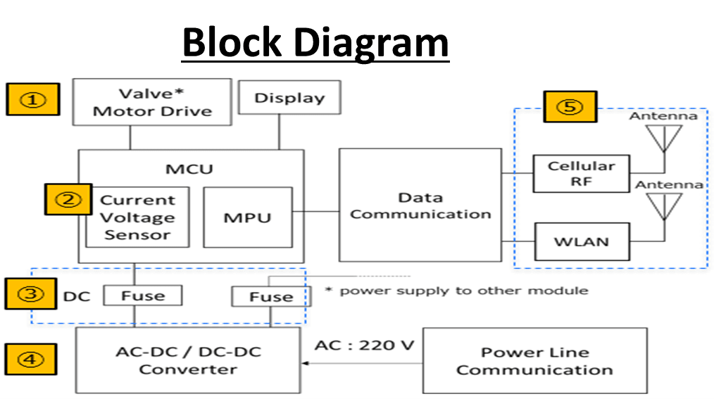
Typically, their circuit diagram is as displayed below:

There are three main areas of a smart meter design, namely the power system, the microcontroller, and the communications interface. The power system has a switched-mode power supply and battery backup to ensure that the metering electronics remain powered even when the mainline is disabled. A Microcontroller Unit (MCU) includes an Analog-to-Digital Converter (ADC) and Digital-to-Analog Converter (DAC) to provide intelligence. And the communication interface allows the meter to interact with the rest of the grid - and in some cases the end user’s network.
Given this brief overview of basic smart meter technology, let’s take a brief trip through the world of passive components and investigate which capacitors, resistors and inductors optimally suit the needs of smart metering applications and why.
At the input side of the power supply circuit, film capacitors are commonly placed in EMI filters for EMI suppression purposes. In order to protect users from harm due to electric shock, X/Y classified EMI suppression film capacitors are normally required with high voltage impulse handling ability.
Taking these requirements into consideration, Panasonic Industry provides an excellent metallized PP film capacitor solution with ECQUA (safety class X2) and ECQUB (safety class X1/Y2) series for high safety and high reliability.
|
Function |
EMI Suppression |
||
|---|---|---|---|
|
Safety class |
X2 |
X1 |
Y2 |
|
Product series |
ECQUA |
ECQUB |
|
|
Voltage |
275VAC, 310VAC |
300VAC |
|
|
Capacitance |
0.0082μF to 10μF |
0.001μF to 1.0μF |
0.001μF to 0.0068μF |
|
Fuse function |
built-in |
built-in |
- |
Thanks to Panasonic’s in-house patterned metallization technology (also known as “fuse function”), ECQUA series and ECQUB series (fuse function applies to class X1 only) offer overvoltage impact reduction and therefore guarantee high safety with open failure mode.
To ensure smart meter reliability also for outdoor metering products - especially under humidity exposure - Panasonic Industry developed its enclosure sealing technology and aluminium vapor deposition to achieve a high humidity resistance.
For smoothing in the input side, typically Tantalum capacitors are employed in parallel since they have a high capacitance level. But they suffer from derating, so for a 12V line, usually 25V caps are used.
To overcome that voltage derating, Panasonic Industry offers Polymer capacitor technology to efficiently replace those tantalums. Polymer caps provide high capacitance values at a very low ESR – in this case, for a 12V line, one 16V POSCAP or OSCON would be the product of choice, combined with reliable performance in a miniaturized housing.
Replacing two Tantalums in parallel with one Polymer capacitor – have a look at the following overview.

Coming to the 3rd main area of a smart meter, the communications interface, amplifier (DSL) circuit is especially important for amplifying the small signals from sensors which are later converted into digital signals that MCU can process. Panasonic Industry provides its stacked metallized film chip-type capacitors to improve the filtering ability in the amplifier circuit.
The stacked metallized PPS film capacitor ECHU(X) series feature stable capacitance characteristics against temperature, frequency and DC bias – next to a very compact size (down to 0603). And there is no need for concerns about piezoelectric effects as known from MLCCs. With its high preciseness for high-speed data transmission, ECHU(X) series is the ideal solution to optimize the design for DSL circuits.

Simplified DSL circuit for smart meter
|
Function |
Filtering |
|---|---|
|
Product series |
ECHU(X) |
|
Category temp. range |
-55℃ to 125℃ |
|
Voltage |
16VDC, 50VDC |
|
Capacitance |
0.1nF to 220nF |
|
Capacitance tolerance |
±2%, ±5% |
|
Dissipation factor (1kHz)(%) |
<0.6 |
Similar to capacitors, resistors can also be used for different purposes in smart meters.
For the motor control of the valve system, it is essential to use resistors with high precision, high reliability, and high stability specs over the entire lifetime of the meter - which is of course meant to be a long one.
Additionally, in the current-voltage sensor, the output signal is highly dependent on the level of accuracy of the resistors employed. Meeting those requirements, Panasonic Industry offers a wide range of high precision resistors in thin-film (ERA* series) and thick film (ERJPB series) technology.
Looking at the DC-DC converter, it is common to use resistors with a higher voltage range and pulse-withstanding capabilities. The wide variety of Panasonic anti-pulse resistors (ERJP/T series) makes it easy to find the perfect component for each and every design.
Occasionally, smart meters are exposed to areas or conditions with tougher environments. Standard resistors sulfurize when getting in contact with above-average concentrations of oil in the air. For this, anti-sulfur resistors come into play, coming with silver or gold layers in the inner terminals to avoid sulfurization.
Panasonic’s anti-sulfur portfolio offers two major product categories, one using silver and one using gold, each in a variety of sizes and resistance values.
In the power supply line, it is crucial to protect the IC from an overcurrent that might even cause a fire. Panasonic Industry chip fuses render an appropriate solution for making sure that the IC - and in the end the entire smart meter - remains safe. Furthermore, for the communication line, no matter if it is cellular RF or Wi-Fi, the signal has to be protected against ESD and noise. The signal processing, however, has to happen with the minimum of signal degrading. Panasonic ESD suppressors can withstand a high amount of ESD with minimum degrading of the signal and minimum insertion loss (S21) of 0.4 pF.

Next to capacitors, the DC/DC input requires also an inductance for current smoothing.
An established technology would be THT wire-wound inductors with a ferrite core. They, however, require considerable space as well as two reflow processes for mounting on the PCB.
Here, Panasonic Industry offers a more elegant solution with the ETQP_L and ETQP_M series, which both provide a much higher energy density that leads to a remarkably higher efficiency due to their innovative metal composite technology.
Therefore, both series only require half the space on the PCB compared to the conventional THT wire-wound inductor. Thanks to SMD mounting, only one reflow process is needed – which of course saves further production time and costs. The images below show an example of the possible differences on a PCB.

The high expectations regarding compact housings, high performance and lifetime: Next-gen smart metering applications meet them, if the used components are the right ones. Manufacturers like Panasonic Industry offer the entire range of passive components, dedicated to the reliability and functionality of tomorrows smart metering innovations.
Undoubtedly, downsizing is a trend in the electronics industry - watch this latest and comprehensive short video and learn what Panasonic Industry has to offer for resistor downsizing - while ensuring the highest power range in smallest case sizes and avoiding the risk of solder joint cracks.
Find more information on resistors by Panasonic Industry Europe here.
In plastic materials that are flame retardant with red phosphorous, outgassing can occur.
This has an impact on electronic components – in relays, for example, it can cause increased contact resistance, and some corrosion phenomena of components on printed circuit board assemblies (PCBAs) can also be traced back to red phosphorous.
In both the outgassing itself and the corrosion process, humidity plays a crucial role. In certain environmental conditions, it leads to the formation of different phosphorous acids and gaseous phosphine.
Now, there is a whitepaper available, comprehensively addressing the phenomenon and discussing ways to tackle it.
On the occcasion of its presentation during the latest International Conference on Electrical Contacts (ICEC), Panasonic Industry's most specialized experts spoke about the influence of plastics containing red phosphorous on electronic components and relays and shared their research of the influence of three differently flame-retarded polyamide (PA) choke coil bobbins on the contact resistances of a nearby unsealed relay.
This illustrated fundamental component design-in insights to overcome contact failures and increase the reliability and lifetime of applications using relays.
For anyone interested in learning more details about this topic, a comprehensive whitepaper from Panasonic's researchers is available free of charge here.
Did you know that not all film capacitors are big fellows with two or four legs as you would commonly guess? And also, that besides the well-known PP and PET dielectric there are
film capacitors using PPS or PEN as a dielectric material?
"The bigger, the better" is no longer necessarily true - and all the more so since
electronics design is evolving continuously. Also miniaturized housings can conceal great amounts of power.
For anyone seeking a capacitor coming in a small case size, with a low-to-high voltage range, high precision and stable capacitance, Panasonic Industry chip type film capacitors could be the ideal solution.
Figure 1: Panasonic Industry Chip Type Film Capacitor line up
Looking at the shape of chip type film capacitors and some of their basic features, one might easily start to wonder: they look pretty much like MLCCs. So, what’s the difference between the two technologies? What are the advantages chip type film capacitors have?
Let’s make a quick comparison to find the answer.
Figure 2: Comparison between Chip Type Film Capacitor and MLCC
Easily being recognized, compared with MLCCs, chip type film capacitors have following advantages in terms of electric characteristics:
Let’s dive into each Panasonic product type to have a better understanding of the technology.
ECHU Type
This type has ECHU(X) and ECHU(C) series available. These two series utilize stacked metallized PPS film as dielectric with simple mold-less construction. They are small in case size (down to 1.6mm x0.8mm footprint!), feature a tight capacitance tolerance of ±2% & ±5%. The capacitance in a single component can go up to 220nF.
ECHU(X) series is available in a low voltage range of 16VDC to 50VDC.
ECHU(C) series is available in a middle voltage range of 100VDC.
Figure 3: Construction of ECHU(X) type
Figure 4: Construction of ECHU(C) type
Now, let’s take a closer look at ECHU(X) series.
As mentioned earlier, ECHU(X) series is focusing on low voltage range of 16VDC to 50VDC.
It benefits from excellent electric characteristics of low ESR, low loss, stable capacitance against temperature and DC bias.
Figure 5: ECHU(X) has excellent electric characteristics
This makes ECHU(X) series the most suitable solution for filtering in xDSL circuit of class D amplifiers for speakers, smartphones and wireless communication etc., as well as for LED circuits.
Figure 6: ECHU(X) series is the ideal solution for xDSL and LED circuit
Furthermore, it guarantees a very fast lock-up time and doesn’t show a piezoelectric effect as MLCCs do, which makes it a perfect solution for PLL (phase locked loop) circuit in applications such as smart phones, wireless communication and Bluetooth devices etc.
Figure 7: ECHU(X) series is ideal solution for PLL circuit
ECPU Type
This type has ECPU(A) series available. This series utilizes stacked metallized plastic film as dielectric and inner electrode with simple mold-less construction. It features a wide capacitance range up to 1.0μF within an ultra-small case size (only 3.2mm x2.5mm footprint for 1.0μF!).
Figure 8: Construction of ECPU(A) type
ECPU(A) series benefits from excellent electric characteristics as low ESR, low loss and stable capacitance over temperature. All this enables its outstanding performance for noise reduction in measurement circuits.
Figure 9: ECPU(A) has excellent electric characteristics
And with ultra-low distortion characteristics being added, ECPU(A) is the most appropriate capacitor solution for coupling in audio circuits.
Figure 10: ECPU(A) series features ultra-low distortion
ECWU Type
Lastly, let’s check out the ECWU type. This type has ECWU(C) series available.
This series is based on stacked metallized PEN film as dielectric with simple mold-less construction. Like the other two types introduced earlier, this series also features a small case size while covering a wide voltage range up to 630VDC.
Figure 11: Construction of ECWU(C) type
High precision, high performance – and contemporarily miniaturized: An ideal choice for
optimizing countless electronic circuit designs.