element14 Community
element14 Community
    Register Log In
  • Site
  • Search
  • Log In Register
  • Community Hub
    Community Hub
    • What's New on element14
    • Feedback and Support
    • Benefits of Membership
    • Personal Blogs
    • Members Area
    • Achievement Levels
  • Learn
    Learn
    • Ask an Expert
    • eBooks
    • element14 presents
    • Learning Center
    • Tech Spotlight
    • STEM Academy
    • Webinars, Training and Events
    • Learning Groups
  • Technologies
    Technologies
    • 3D Printing
    • FPGA
    • Industrial Automation
    • Internet of Things
    • Power & Energy
    • Sensors
    • Technology Groups
  • Challenges & Projects
    Challenges & Projects
    • Design Challenges
    • element14 presents Projects
    • Project14
    • Arduino Projects
    • Raspberry Pi Projects
    • Project Groups
  • Products
    Products
    • Arduino
    • Avnet Boards Community
    • Dev Tools
    • Manufacturers
    • Multicomp Pro
    • Product Groups
    • Raspberry Pi
    • RoadTests & Reviews
  • Store
    Store
    • Visit Your Store
    • Choose another store...
      • Europe
      •  Austria (German)
      •  Belgium (Dutch, French)
      •  Bulgaria (Bulgarian)
      •  Czech Republic (Czech)
      •  Denmark (Danish)
      •  Estonia (Estonian)
      •  Finland (Finnish)
      •  France (French)
      •  Germany (German)
      •  Hungary (Hungarian)
      •  Ireland
      •  Israel
      •  Italy (Italian)
      •  Latvia (Latvian)
      •  
      •  Lithuania (Lithuanian)
      •  Netherlands (Dutch)
      •  Norway (Norwegian)
      •  Poland (Polish)
      •  Portugal (Portuguese)
      •  Romania (Romanian)
      •  Russia (Russian)
      •  Slovakia (Slovak)
      •  Slovenia (Slovenian)
      •  Spain (Spanish)
      •  Sweden (Swedish)
      •  Switzerland(German, French)
      •  Turkey (Turkish)
      •  United Kingdom
      • Asia Pacific
      •  Australia
      •  China
      •  Hong Kong
      •  India
      •  Korea (Korean)
      •  Malaysia
      •  New Zealand
      •  Philippines
      •  Singapore
      •  Taiwan
      •  Thailand (Thai)
      • Americas
      •  Brazil (Portuguese)
      •  Canada
      •  Mexico (Spanish)
      •  United States
      Can't find the country/region you're looking for? Visit our export site or find a local distributor.
  • Translate
  • Profile
  • Settings
RoadTests & Reviews
  • Products
  • More
RoadTests & Reviews
Blog TI Ultrasonic Sensor - Show 3 Signals on a 2 Channel Oscilloscope (RIGOL DS1052E)
  • Blog
  • RoadTest Forum
  • Documents
  • RoadTests
  • Reviews
  • Polls
  • Files
  • Members
  • Mentions
  • Sub-Groups
  • Tags
  • More
  • Cancel
  • New
Join RoadTests & Reviews to participate - click to join for free!
  • Share
  • More
  • Cancel
  • Author Author: Jan Cumps
  • Date Created: 20 Dec 2015 7:40 PM Date Created
  • Views 1730 views
  • Likes 4 likes
  • Comments 3 comments
Related
Recommended
  • RoadTest
  • ds1052e
  • tdc1000-tdc7200evm
  • ultrasonic_sensor
  • steminc
  • texas_instruments
  • tdc1000
  • rigol

TI Ultrasonic Sensor - Show 3 Signals on a 2 Channel Oscilloscope (RIGOL DS1052E)

Jan Cumps
Jan Cumps
20 Dec 2015

The  TDC1000-TDC7200EVMTDC1000-TDC7200EVM evaluation module has 4 main parts

The TDC1000 analog front-end and a pre-programmed MSP430 microcontroller on the board, a 1MHz Piezo Ceramic sensor that plugs into the board and a GUI client for on your PC.


In this blog I measure the start and stop pulse, and show how you can display 3 signals on a 2 channel oscilloscope.


You don't have permission to edit metadata of this video.
Edit media
x
image
Upload Preview
image


What are we Measuring


The evaluation kit has 3 test points that are of particular interest:

  • the start pulse - the moment that the board sends the ultrasonic signal to the piezo transducer
  • the compin signal - the echo signal returned by the piezo element
  • the stop signal - the TDC1000 sends this pulse after it has detected the same number of zero crossings in the compin signal as it has sent out.


Some Theory

I've configured the evaluation board to send 5 pulses. The TDC1000 creates a 1MHz sinusoidal signal with 5 cycles and agitates the piezo transducer with that signal.

The signal travels through the water, and bounces back when it hits the surface (the boundary between water and air is a reflector for 1 MHz signals).

The reflection of that signal is picked up by the piezo transducer and sent back to the board.

As soon as the returned signal exceeds a threshold, the TDC1000 starts counting how many times the returned signal crosses the zero, on the positive edge.

After 5 crossings the TDC1000 generates the stop signal.


image

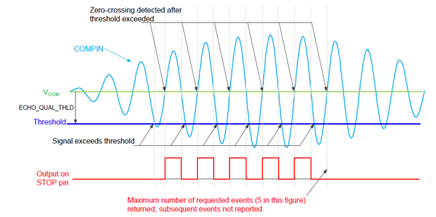
image source: TDC1000 data sheet


The Expected Result


We're expecting to see these 3 correlated signals on our oscilloscope (this image is from the User's Guide, made with a "more than 2 channel" scope):

image

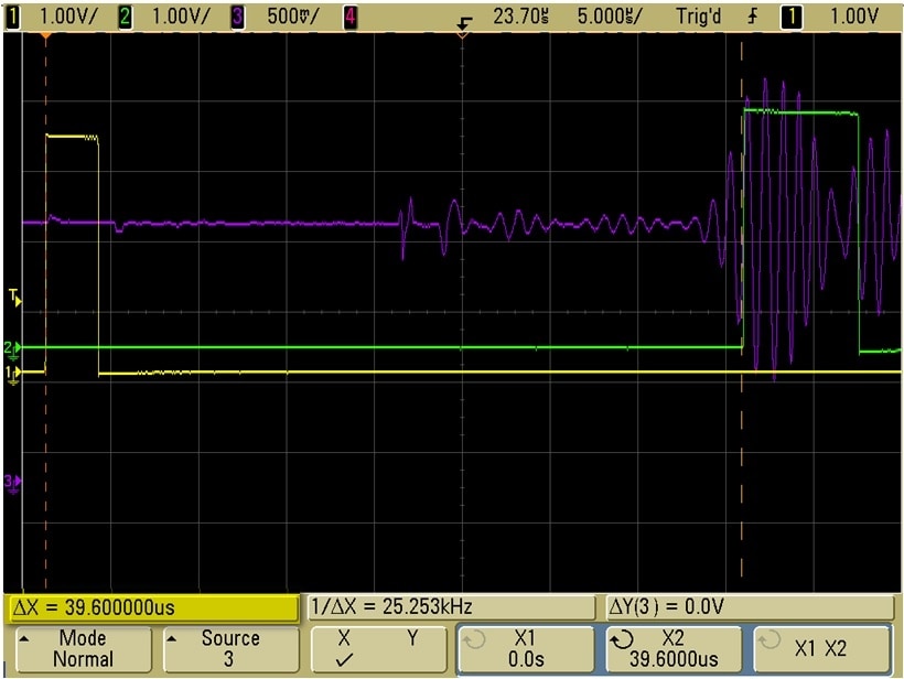
image source tdc1000-tdc7200evm User's Guide


The yellow line is the start pulse, the purple one is the echo of the transducer. The stop pulse, generated after 5 zero crossings, is green.

We're interested in the time between the rising edge of yellow and green. That's an indicator of the back-and-forth time of our signal through the liquid.

note: take care that you enable continuous triggering on the TDC1000 tab of the evaluation board's GUI.


My Scope Only Has 2 Channels


Sometimes it's a blessing to have limited resources. It forces you to be inventive. You'll have to find solutions - and you learn more about your test equipment.


It is true that my scope is 2 channel. That would mean that I'd have to ignore one of the 3 signals when probing. And that's OK. You can analyze the functionality by looking at two signals each time.

  • probe start + compin, and see how long it takes for the echo to return (trigger on start rising edge)
  • probe start + stop, and measure the time between both rising edges (trigger on start rising edge). That's the travel time of the signal from sensor to surface and back
  • probe stop and compin (trigger on stop rising edge - put the trigger point near the right end of the scope screen). The trigger point is the nth zero crossing of the composite signal.


Rigol DS1052E REF function

But it would be more intuitive to show the 3 signals in one picture. And that's possible, because we have one signal that's always fixed: the start signal. And it's our trigger point - so this signal will always have a fixed position on our screen.

It's a signal with fixed frequency, length and amplitude. A good candidate to store the start pulse as a Reference Signal, using your scope's REF memory.

The REF function (search the Rigol's User's Guide for "Using REF") allows you to capture a waveform and freeze it on the display. The DS1052E shows it as a white waveform.


image


You can remove the channel A probe from the START test point. The reference signal stays on the screen. You can use the vertical position button to move it out of the way.


But Wait, I Was Triggering on the Start Pulse


... so when I take away the probe A from the START test point, I loose my trigger base, don't I?

External trigger to the rescue. The DS1052E allows you to trigger on a signal that's not channel A or B.

We can connect the EXT TRIG input to the START test point, and set up external triggering.

Open the trigger menu, set the source to EXT, and play with the level button until the scope triggers reliably. You can see this when the T'D label appears, and the orange T icon appears above the rising edge of the reference signal.


tip: it's easier to do this exercise when both EXT TRIG and channel A are connected to the START signal of the evaluation board.

You have a stable external trigger when the yellow signal shows stable on the screen, with it's rising edge exactly at the same horizontal position as the one of the white reference waveform.

You can safely remove the channel A test probe from the START test point when this is achieved.


Once you've established a stable external trigger on the start signal, you can connect channel A to the compin test point and channel B to the STOP test point.

You now have the 3 signals on the screen, and can use the scope's cursors to analyse the display.


image


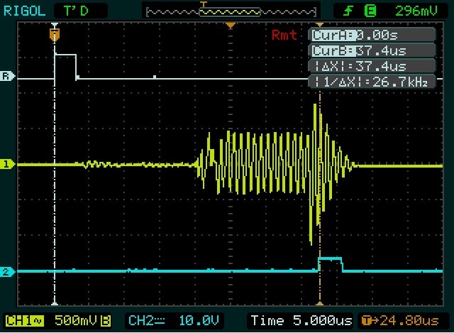
In my test setup, the signal has traveled 37.4 µs through the fluid. That is 18.7 up and 18.7 back down. When you know that the speed of sound through water is approx. 1480 m/s, you can do the math.


I got a bit sidetracked in this blog post. My aim was to talk about measuring the analog, digital and acoustic signals flying through board and liquid-under-test. It turned into a scope probing technique story.

Maybe you find this useful in your own measuring activities...


Related Posts
RoadTest: Unboxing the TI Ultrasonic Sensing evaluation module
TI Ultrasonic Sensor - A Very First Trial of the GUI
TI Ultrasonic Sensor - Prepping the Transponder
TI Ultrasonic Sensor - First Measurements
TI Ultrasonic Sensor - Set the Parameters for Level Measurement and Content Identification
TI Ultrasonic Sensor - Show 3 Signals on a 2 Channel Oscilloscope (RIGOL DS1052E)
TI Ultrasonic Sensor - Liquid Identification and Concentration
TI Ultrasonic Sensor - Create a KiCad Part for the Sensor IC with KiPart
TI Ultrasonic Sensor - SPI Traffic Snooping

TI Ultrasonic Sensor - RoadTest Review

  • Sign in to reply

Top Comments

  • DAB
    DAB over 9 years ago +1
    Great post Jan, I like your solution with three signals on a two channel scope. DAB
  • Jan Cumps
    Jan Cumps over 9 years ago in reply to DAB +1
    I used to own a late 80's Philips PM3305 4 channel scope. i could display 8 traces with that . This was an amazing piece at its time.
  • mcb1
    mcb1 over 9 years ago +1
    Well done. I never really thought about using the ext trigger in that manner. As you said Sometimes it's a blessing to have limited resources. It forces you to be inventive Mark
  • mcb1
    mcb1 over 9 years ago

    Well done.


    I never really thought about using the ext trigger in that manner.

    As you said

    Sometimes it's a blessing to have limited resources. It forces you to be inventive


    Mark

    • Cancel
    • Vote Up +1 Vote Down
    • Sign in to reply
    • More
    • Cancel
  • Jan Cumps
    Jan Cumps over 9 years ago in reply to DAB

    I used to own a late 80's Philips PM3305 4 channel scope.

    i could display 8 traces with that image.


    image


    This was an amazing piece at its time.

    • Cancel
    • Vote Up +1 Vote Down
    • Sign in to reply
    • More
    • Cancel
  • DAB
    DAB over 9 years ago

    Great post Jan,


    I like your solution with three signals on a two channel scope.


    DAB

    • Cancel
    • Vote Up +1 Vote Down
    • Sign in to reply
    • More
    • Cancel
element14 Community

element14 is the first online community specifically for engineers. Connect with your peers and get expert answers to your questions.

  • Members
  • Learn
  • Technologies
  • Challenges & Projects
  • Products
  • Store
  • About Us
  • Feedback & Support
  • FAQs
  • Terms of Use
  • Privacy Policy
  • Legal and Copyright Notices
  • Sitemap
  • Cookies

An Avnet Company © 2025 Premier Farnell Limited. All Rights Reserved.

Premier Farnell Ltd, registered in England and Wales (no 00876412), registered office: Farnell House, Forge Lane, Leeds LS12 2NE.

ICP 备案号 10220084.

Follow element14

  • X
  • Facebook
  • linkedin
  • YouTube