element14 Community
element14 Community
    Register Log In
  • Site
  • Search
  • Log In Register
  • About Us
  • Community Hub
    Community Hub
    • What's New on element14
    • Feedback and Support
    • Benefits of Membership
    • Personal Blogs
    • Members Area
    • Achievement Levels
  • Learn
    Learn
    • Ask an Expert
    • eBooks
    • element14 presents
    • Learning Center
    • Tech Spotlight
    • STEM Academy
    • Webinars, Training and Events
    • Learning Groups
  • Technologies
    Technologies
    • 3D Printing
    • FPGA
    • Industrial Automation
    • Internet of Things
    • Power & Energy
    • Sensors
    • Technology Groups
  • Challenges & Projects
    Challenges & Projects
    • Design Challenges
    • element14 presents Projects
    • Project14
    • Arduino Projects
    • Raspberry Pi Projects
    • Project Groups
  • Products
    Products
    • Arduino
    • Avnet Boards Community
    • Dev Tools
    • Manufacturers
    • Multicomp Pro
    • Product Groups
    • Raspberry Pi
    • RoadTests & Reviews
  • Store
    Store
    • Visit Your Store
    • Choose another store...
      • Europe
      •  Austria (German)
      •  Belgium (Dutch, French)
      •  Bulgaria (Bulgarian)
      •  Czech Republic (Czech)
      •  Denmark (Danish)
      •  Estonia (Estonian)
      •  Finland (Finnish)
      •  France (French)
      •  Germany (German)
      •  Hungary (Hungarian)
      •  Ireland
      •  Israel
      •  Italy (Italian)
      •  Latvia (Latvian)
      •  
      •  Lithuania (Lithuanian)
      •  Netherlands (Dutch)
      •  Norway (Norwegian)
      •  Poland (Polish)
      •  Portugal (Portuguese)
      •  Romania (Romanian)
      •  Russia (Russian)
      •  Slovakia (Slovak)
      •  Slovenia (Slovenian)
      •  Spain (Spanish)
      •  Sweden (Swedish)
      •  Switzerland(German, French)
      •  Turkey (Turkish)
      •  United Kingdom
      • Asia Pacific
      •  Australia
      •  China
      •  Hong Kong
      •  India
      •  Korea (Korean)
      •  Malaysia
      •  New Zealand
      •  Philippines
      •  Singapore
      •  Taiwan
      •  Thailand (Thai)
      • Americas
      •  Brazil (Portuguese)
      •  Canada
      •  Mexico (Spanish)
      •  United States
      Can't find the country/region you're looking for? Visit our export site or find a local distributor.
  • Translate
  • Profile
  • Settings
Connector Technology & Design
  • Technologies
  • More
Connector Technology & Design
Forum Overview: Amphenol / SV Microwave SF2921-61506-1S SMA coaxial connector series
  • Blog
  • Forum
  • Documents
  • Quiz
  • Events
  • Polls
  • Files
  • Members
  • Mentions
  • Sub-Groups
  • Tags
  • More
  • Cancel
  • New
Join Connector Technology & Design to participate - click to join for free!
Actions
  • Share
  • More
  • Cancel
Forum Thread Details
  • Replies 11 replies
  • Subscribers 127 subscribers
  • Views 3088 views
  • Users 0 members are here
  • sv microwave
  • amphenol
  • SF2921-61506
  • SF2921-61506-1S
Related

Overview: Amphenol / SV Microwave SF2921-61506-1S SMA coaxial connector series

Jan Cumps
Jan Cumps over 2 years ago

imageBlog Index

  • Overview: Amphenol / SV Microwave SF2921-61506-1S SMA coaxial connector series
  • Amphenol / SV Microwave SF2921-61506-1S SMA coaxial connector: behavior under vibration
  • Create a custom footprint in KiCad 7 - 1: collect info and component details
  • Create a custom footprint in KiCad 7 - 2a: create the footprint for an SMA coax connector with the editor - initial outline
  • Create a custom footprint in KiCad 7 - 2b: create the footprint for an SMA coax connector with the editor - copper pour, solder mask clearance, holes, pads
  • Use a LibraryLoader Footprint in KiCad 7

I'm testing a set of Amphenol /  SV Microwave SF2921-61506-1S  SMA coaxial connectors. 

image

I'll cover 3 angles:

Footprint and PCB layout

This part focuses on getting a good PCB layout for the connector, that can be used for a microstrip design.

image

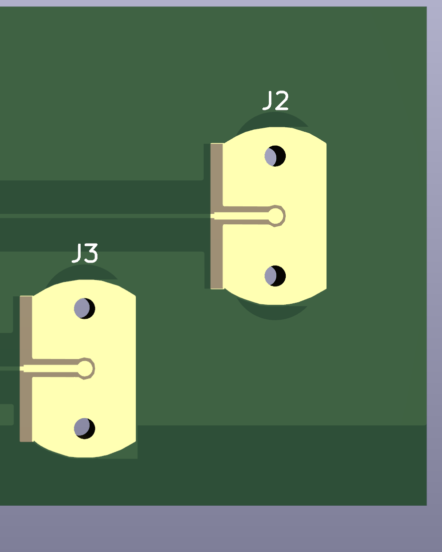
It starts from a community sourced footprint, ending with a clean layout. This part was a collaboration exercise with shabaz. We both designed footprints, using the same editor, but different approaches.

  •  Use a LibraryLoader Footprint in KiCad 7 
  •  Create a custom footprint in KiCad 7 - 1: collect info and component details 
  •  Create a custom footprint in KiCad 7 - 2a: create the footprint for an SMA coax connector with the editor - initial outline 
  •  Create a custom footprint in KiCad 7 - 2b: create the footprint for an SMA coax connector with the editor - copper pour, solder mask clearance, holes, pads 

image

Spring contact resilience to vibrations

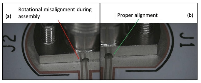
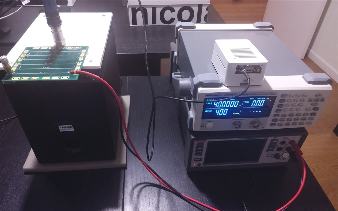
The connector's main difference with other PCB mount coaxial models, is that it's spring-actioned instead of soldered-on. I use the vibration table and measurement tools from the Vibration Measurement with the MCC 172 roadtest. During the test, I check if the DC resistance alters under vibration, or if the contact interrupts.
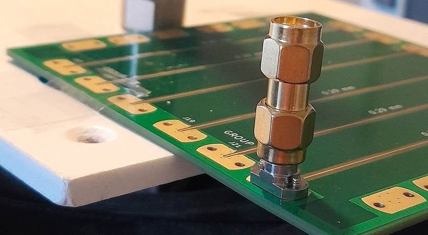
image

  •  Amphenol / SV Microwave SF2921-61506-1S SMA coaxial connector: behavior under vibration 

Connector in use

I'll check the connector with the microstrip designs that shabaz made, and in combination of a set of antennas I have, from a Molex kit and a Texas Instruments PCB antenna design kit.

Link to all posts

  • Sign in to reply
  • Cancel

Top Replies

  • scottiebabe
    scottiebabe over 2 years ago +4
    Nice work! I read this article yesterday and thought of you lol Are the authors over exaggerating the alignment process? https://www.everythingrf.com/news/details/15928-samtec-develops-visual-alignment…
  • Jan Cumps
    Jan Cumps over 2 years ago in reply to dang74 +3
    I'm working on the setup:
  • shabaz
    shabaz over 2 years ago +2
    This will be a great test! Looking forward to seeing how it goes.
  • shabaz
    shabaz over 2 years ago

    This will be a great test! Looking forward to seeing how it goes.

    • Cancel
    • Vote Up +2 Vote Down
    • Sign in to reply
    • Cancel
  • dang74
    dang74 over 2 years ago

    This is a very interesting study.  If you have access to a spectrum analyzer you could also look to see if any spurs occur offset from the main tone by the vibration frequency.

    • Cancel
    • Vote Up 0 Vote Down
    • Sign in to reply
    • Cancel
  • Jan Cumps
    Jan Cumps over 2 years ago in reply to dang74

    I don't have a spectrum analyzer or high frequency instruments. That's why I chose to focus on the physical / mechanical differences compared to solder-on connectors.

    • Cancel
    • Vote Up +2 Vote Down
    • Sign in to reply
    • Cancel
  • dang74
    dang74 over 2 years ago in reply to Jan Cumps

    No problem.  It's certainly a pretty novel connector type.  It will be interesting to see whether or not you see any significant differences in DC resistance during vibration.

    • Cancel
    • Vote Up +1 Vote Down
    • Sign in to reply
    • Cancel
  • scottiebabe
    scottiebabe over 2 years ago

    Nice work! I read this article yesterday and thought of you lol

    Are the authors over exaggerating the alignment process?

    image

    https://www.everythingrf.com/news/details/15928-samtec-develops-visual-alignment-technique-for-precision-high-frequency-compression-mount-connectors 

    • Cancel
    • Vote Up +4 Vote Down
    • Sign in to reply
    • Cancel
  • shabaz
    shabaz over 2 years ago in reply to Jan Cumps

    I think it would be hard with a spectrum analyzer, since it might be tiny modulation (e.g. if the resistance slightly changes), and it would be so close to the main signal. 

    I'm focussing on low-frequency applications too (since SMA connectors are needed for all sorts of stuff), and I'm only using FR4, so will do some measurements at RF, but it won't be much beyond a GHz or so, since we are manually trying different footprint and microstrip widths to iterate down to 50 ohm, and there are only 12 or so shots at getting it right, on a single board; to do it properly, we would need to model it ($$$$$$ of cost) or SV Micro would need to provide a footprint to suit the PCB.

    • Cancel
    • Vote Up +2 Vote Down
    • Sign in to reply
    • Cancel
  • DAB
    DAB over 2 years ago

    I look forward to seeing what you find.

    • Cancel
    • Vote Up +1 Vote Down
    • Sign in to reply
    • Cancel
  • Jan Cumps
    Jan Cumps over 2 years ago in reply to dang74

    I'm working on the setup:

    image

    • Cancel
    • Vote Up +3 Vote Down
    • Sign in to reply
    • Cancel
  • dang74
    dang74 over 2 years ago in reply to Jan Cumps

    Nice. Slight smile That's quite the setup.

    • Cancel
    • Vote Up 0 Vote Down
    • Sign in to reply
    • Cancel
  • Jan Cumps
    Jan Cumps over 2 years ago in reply to scottiebabe

    I was not able to reproduce this tilted mounting - or even something near to that - with shabaz ' footprint and the provided mounting hardware. I used reasonable force to screw connectors / antennas on and this didn't happen. I also shaked it for long time on the mechanical resonance frequency.

    • Cancel
    • Vote Up +2 Vote Down
    • Sign in to reply
    • Cancel
>
element14 Community

element14 is the first online community specifically for engineers. Connect with your peers and get expert answers to your questions.

  • Members
  • Learn
  • Technologies
  • Challenges & Projects
  • Products
  • Store
  • About Us
  • Feedback & Support
  • FAQs
  • Terms of Use
  • Privacy Policy
  • Legal and Copyright Notices
  • Sitemap
  • Cookies

An Avnet Company © 2025 Premier Farnell Limited. All Rights Reserved.

Premier Farnell Ltd, registered in England and Wales (no 00876412), registered office: Farnell House, Forge Lane, Leeds LS12 2NE.

ICP 备案号 10220084.

Follow element14

  • X
  • Facebook
  • linkedin
  • YouTube