Blog Index
- Overview: Amphenol / SV Microwave SF2921-61506-1S SMA coaxial connector series
- Amphenol / SV Microwave SF2921-61506-1S SMA coaxial connector: behavior under vibration
- Create a custom footprint in KiCad 7 - 1: collect info and component details
- Create a custom footprint in KiCad 7 - 2a: create the footprint for an SMA coax connector with the editor - initial outline
- Create a custom footprint in KiCad 7 - 2b: create the footprint for an SMA coax connector with the editor - copper pour, solder mask clearance, holes, pads
- Use a LibraryLoader Footprint in KiCad 7
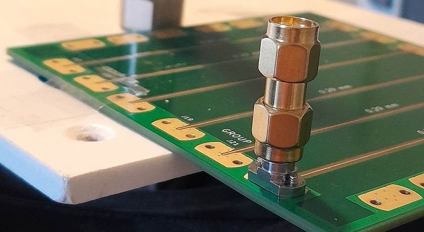
I'm testing a set of Amphenol / SV Microwave SF2921-61506-1S SMA coaxial connectors.

I'll cover 3 angles:
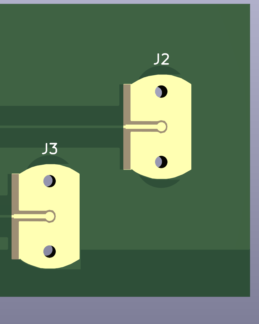
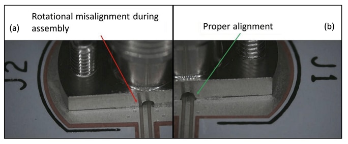
Footprint and PCB layout
This part focuses on getting a good PCB layout for the connector, that can be used for a microstrip design.

It starts from a community sourced footprint, ending with a clean layout. This part was a collaboration exercise with shabaz. We both designed footprints, using the same editor, but different approaches.
- Use a LibraryLoader Footprint in KiCad 7
- Create a custom footprint in KiCad 7 - 1: collect info and component details
- Create a custom footprint in KiCad 7 - 2a: create the footprint for an SMA coax connector with the editor - initial outline
- Create a custom footprint in KiCad 7 - 2b: create the footprint for an SMA coax connector with the editor - copper pour, solder mask clearance, holes, pads

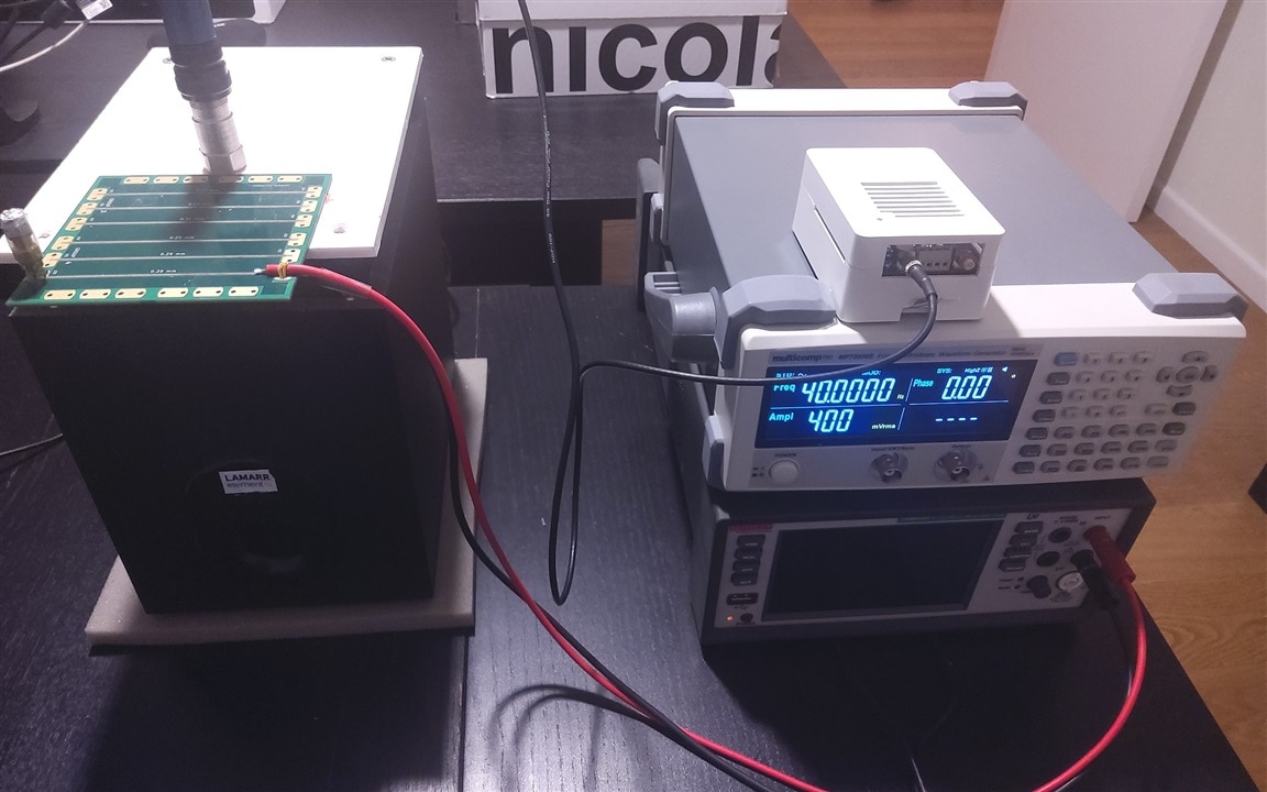
Spring contact resilience to vibrations
The connector's main difference with other PCB mount coaxial models, is that it's spring-actioned instead of soldered-on. I use the vibration table and measurement tools from the Vibration Measurement with the MCC 172 roadtest. During the test, I check if the DC resistance alters under vibration, or if the contact interrupts.

Connector in use
I'll check the connector with the microstrip designs that shabaz made, and in combination of a set of antennas I have, from a Molex kit and a Texas Instruments PCB antenna design kit.


