element14 Community
element14 Community
    Register Log In
  • Site
  • Search
  • Log In Register
  • Community Hub
    Community Hub
    • What's New on element14
    • Feedback and Support
    • Benefits of Membership
    • Personal Blogs
    • Members Area
    • Achievement Levels
  • Learn
    Learn
    • Ask an Expert
    • eBooks
    • element14 presents
    • Learning Center
    • Tech Spotlight
    • STEM Academy
    • Webinars, Training and Events
    • Learning Groups
  • Technologies
    Technologies
    • 3D Printing
    • FPGA
    • Industrial Automation
    • Internet of Things
    • Power & Energy
    • Sensors
    • Technology Groups
  • Challenges & Projects
    Challenges & Projects
    • Design Challenges
    • element14 presents Projects
    • Project14
    • Arduino Projects
    • Raspberry Pi Projects
    • Project Groups
  • Products
    Products
    • Arduino
    • Avnet Boards Community
    • Dev Tools
    • Manufacturers
    • Multicomp Pro
    • Product Groups
    • Raspberry Pi
    • RoadTests & Reviews
  • Store
    Store
    • Visit Your Store
    • Choose another store...
      • Europe
      •  Austria (German)
      •  Belgium (Dutch, French)
      •  Bulgaria (Bulgarian)
      •  Czech Republic (Czech)
      •  Denmark (Danish)
      •  Estonia (Estonian)
      •  Finland (Finnish)
      •  France (French)
      •  Germany (German)
      •  Hungary (Hungarian)
      •  Ireland
      •  Israel
      •  Italy (Italian)
      •  Latvia (Latvian)
      •  
      •  Lithuania (Lithuanian)
      •  Netherlands (Dutch)
      •  Norway (Norwegian)
      •  Poland (Polish)
      •  Portugal (Portuguese)
      •  Romania (Romanian)
      •  Russia (Russian)
      •  Slovakia (Slovak)
      •  Slovenia (Slovenian)
      •  Spain (Spanish)
      •  Sweden (Swedish)
      •  Switzerland(German, French)
      •  Turkey (Turkish)
      •  United Kingdom
      • Asia Pacific
      •  Australia
      •  China
      •  Hong Kong
      •  India
      •  Korea (Korean)
      •  Malaysia
      •  New Zealand
      •  Philippines
      •  Singapore
      •  Taiwan
      •  Thailand (Thai)
      • Americas
      •  Brazil (Portuguese)
      •  Canada
      •  Mexico (Spanish)
      •  United States
      Can't find the country/region you're looking for? Visit our export site or find a local distributor.
  • Translate
  • Profile
  • Settings
Embedded and Microcontrollers
  • Technologies
  • More
Embedded and Microcontrollers
Blog MAX32660 Evaluation Kit - part 4c: Low Power Sensor design - Barometer, Not Yet Power Optimised
  • Blog
  • Forum
  • Documents
  • Quiz
  • Polls
  • Files
  • Members
  • Mentions
  • Sub-Groups
  • Tags
  • More
  • Cancel
  • New
Embedded and Microcontrollers requires membership for participation - click to join
  • Share
  • More
  • Cancel
Group Actions
  • Group RSS
  • More
  • Cancel
Engagement
  • Author Author: Jan Cumps
  • Date Created: 17 Dec 2018 7:39 PM Date Created
  • Views 2295 views
  • Likes 6 likes
  • Comments 11 comments
  • RoadTest
  • rohm
  • rt
  • max32660
  • maxim
  • road_test
Related
Recommended

MAX32660 Evaluation Kit - part 4c: Low Power Sensor design - Barometer, Not Yet Power Optimised

Jan Cumps
Jan Cumps
17 Dec 2018

I'm road testing the  Ultra-Low Power Arm Cortex-M4 Darwin MCU EVM.

In these blog posts I try to build a real world low power design. A barometer using  the pressure sensor BM1383AGLV BM1383AGLV from the Rohm SensorShield-EVK-003 (Arduino Compatible)  kit.


In this part, the project is functional .But not yet using power save options.

image


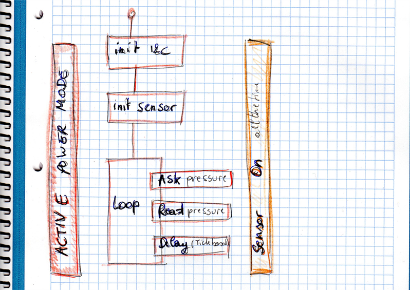
Barometer Firmware Flow


This is a straightforward design.

  • processor in active mode, peripherals on
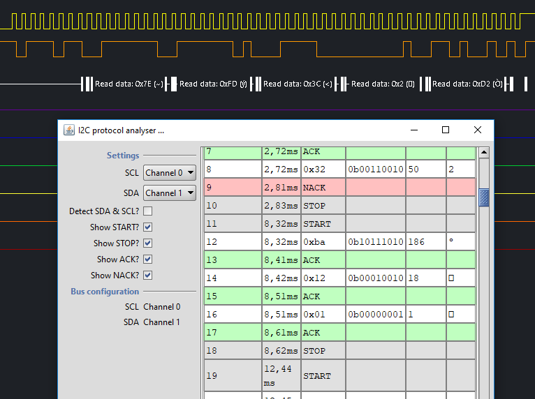
  • !2c initialised
  • sensor initialised
  • a loop that
    • polls the sensors and retrieves the data
    • waits 500 ms

image


The firmware also logs info to the console over USB, but I deactivate these functions before making any power measurements.

This code (all printf() ) is just used during the development cycle.


Power Profile


image


As you can see above, the processor runs in the most power expensive mode. All the time.

I won't go over the options available to save power. That's for a next post. Just review where the inefficiencies are:


  • We always run in active mode.
  • all modules are turned on, also the ones that we don't use. Same for RAM.
  • We're using the maximum frequency of the microcontroller
  • in the loop - where the program spends virtually all of its active life -  most of the time is spent waiting, with the heating on image.
    the loop is approx 500 ms (a delay of 500, and a few ms to exchange data with the sensor)
  • sensor is powered all the time.
  • sensor is in active mode all the time, even though we know that it can start up and initialise in say 4 ms and deliver new data in 2 ms.


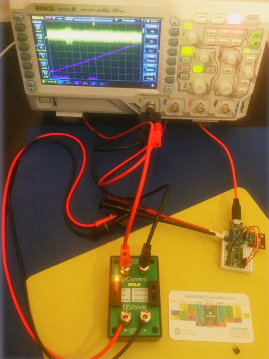
Measure the Consumption


I'm using my oscilloscope's integration function to get the power over a significant time.

I'll redo this exercise whenever I (think I will) make a significant power save step in future posts.


Current is converted by a µCurrent. 1 mV represents 1 mA. Power source is 1.8 V.

image


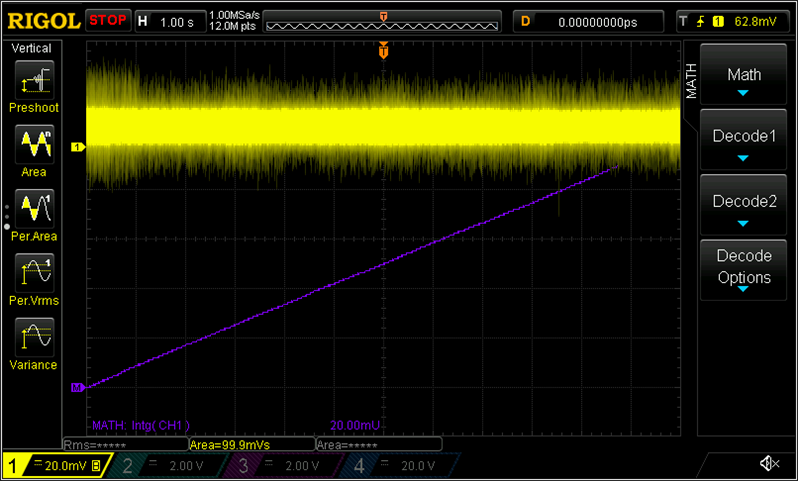
The time base is 1 second per division. Total 12 seconds. We capture 23 and a bit loops of the controller.

The A signal is set to 20 mv / division

Math is set to integral of channel A; 20 mUnits / division.

I've also used a measure to calculate the area under A. That should give the same result as the math signal at the end of the X scale.

I've redrawn the integral by hand for clarity (I haven't found a way to give the math channel focus on my scope).


image

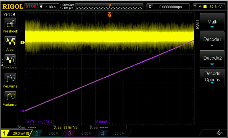
Measure says I consumed 100 mVs. The math function shows just a tad over 5 divisions, 100 mUnits.

This is measured with the device in continuous mode, so the startup power is ignored. That's on purpose.


Now that I know that I've burned 100 mVs, measured over 12 seconds, I have a reference for the optimisation exercise.

Multiply by 1.8 V then divide by a magic number to know the amphours.

disclaimer: I haven't validated this. Maybe my reasoning is off and the measure vs math values seem to match by accident. I'd trust the math's integral value more.

But then I have to look up in the manual what 20 mU means, in relation to the settings of channel A.

If you know, tell me.


The Eclipse project with sources, for this phase of the experiment, is attached.


part 1: IDE install and Build First Example
part 2: Mod the PCB for Power Measurement
part 3: Power Measurement
part 4a: Low Power Sensor design - Barometer Hardware
part 4b: Low Power Sensor design - Barometer i2c and Init
part 4c: Low Power Sensor design - Barometer, Not Yet Power Optimised
MAX32660 Evaluation Kit - part 5: FreeRTOS Example
side note A: C++ Eclipse Project
side note B: Create a Release Configuration
Attachments:
roadtest_project.zip
donttryathome_roadtest_project_optimise.zip
  • Sign in to reply

Top Comments

  • Jan Cumps
    Jan Cumps over 6 years ago +1
    Note to @self: low power measurements are hard. Use everything the same when measuring. I was getting lower power measurements today. There's a difference if I power this from my laptop or a USB brick…
Parents
  • Jan Cumps
    Jan Cumps over 6 years ago

    I bricked the device when uploading my first low power design. It's a subset of the low power design from Maxim.

    i don't know why the controller is stuck - there was a mix of a SDK update from Maxim gone wrong and me adapting a working project to low power.


    Chances are that I put it in a state that's not reacting on the debugger.


    For the heroes, I've attached a project to this blog called donttryathome_roadtest_project_optimise.zip.

    It is source code and binary. After I uploaded it the device is bricked. My ask is to not try it at home, but maybe look at my code and see if you see a problem.

    • Cancel
    • Vote Up 0 Vote Down
    • Sign in to reply
    • More
    • Cancel
  • Jan Cumps
    Jan Cumps over 6 years ago in reply to Jan Cumps

    Jan Cumps  wrote:


    I bricked the device when uploading my first low power design. It's a subset of the low power design from Maxim.

    i don't know why the controller is stuck - there was a mix of a SDK update from Maxim gone wrong and me adapting a working project to low power.

    ...

    I think I understand why it gets bricked - at least I can replicate it:


    In the LP example, there's this line of code:


            MXC_GCR->scon |= 0x4000;  // Disable SWD


    It disables the single wire debug / JTAG.


    Later on it's enabled again.

    If you loaded that example, or have this line in the firmware, you have to have the luck that the device is not in that particular block when you try to attach a debug session).

    Depending on your design (this is part of the low power part) you may have the mishap that it spends 99 % in that low power mode.

    This is just a theory at the moment.

    • Cancel
    • Vote Up 0 Vote Down
    • Sign in to reply
    • More
    • Cancel
Comment
  • Jan Cumps
    Jan Cumps over 6 years ago in reply to Jan Cumps

    Jan Cumps  wrote:


    I bricked the device when uploading my first low power design. It's a subset of the low power design from Maxim.

    i don't know why the controller is stuck - there was a mix of a SDK update from Maxim gone wrong and me adapting a working project to low power.

    ...

    I think I understand why it gets bricked - at least I can replicate it:


    In the LP example, there's this line of code:


            MXC_GCR->scon |= 0x4000;  // Disable SWD


    It disables the single wire debug / JTAG.


    Later on it's enabled again.

    If you loaded that example, or have this line in the firmware, you have to have the luck that the device is not in that particular block when you try to attach a debug session).

    Depending on your design (this is part of the low power part) you may have the mishap that it spends 99 % in that low power mode.

    This is just a theory at the moment.

    • Cancel
    • Vote Up 0 Vote Down
    • Sign in to reply
    • More
    • Cancel
Children
  • Jan Cumps
    Jan Cumps over 6 years ago in reply to Jan Cumps

    Let's see what my fellow road testers think after they tried to build a low power design, but I believe this is an issue if a board can be locked fairly easily.

    You may call me a bad programmer because I make bugs image and I accept that.


    I'll remove the MAX32660 from the PCB and put a new one on - glad that MAXIM sent me a few samples

    I'll hold off trying low power again until I saw success from others. That's a pity because I wanted to use this to show how power profiling works with Keithley DMM6500.


    edit: I still have a second kit that I bought here in Brussels. I will reserve that for designs that don't use deep sleep image

    • Cancel
    • Vote Up 0 Vote Down
    • Sign in to reply
    • More
    • Cancel
  • Jan Cumps
    Jan Cumps over 6 years ago in reply to Jan Cumps

    Jan Cumps  wrote:


    ...


    I'll remove the MAX32660 from the PCB and put a new one on - glad that MAXIM sent me a few samples

    ...

    WIP:

    image

    • Cancel
    • Vote Up 0 Vote Down
    • Sign in to reply
    • More
    • Cancel
  • Jan Cumps
    Jan Cumps over 6 years ago in reply to Jan Cumps

    done


    image

    • Cancel
    • Vote Up 0 Vote Down
    • Sign in to reply
    • More
    • Cancel
element14 Community

element14 is the first online community specifically for engineers. Connect with your peers and get expert answers to your questions.

  • Members
  • Learn
  • Technologies
  • Challenges & Projects
  • Products
  • Store
  • About Us
  • Feedback & Support
  • FAQs
  • Terms of Use
  • Privacy Policy
  • Legal and Copyright Notices
  • Sitemap
  • Cookies

An Avnet Company © 2025 Premier Farnell Limited. All Rights Reserved.

Premier Farnell Ltd, registered in England and Wales (no 00876412), registered office: Farnell House, Forge Lane, Leeds LS12 2NE.

ICP 备案号 10220084.

Follow element14

  • X
  • Facebook
  • linkedin
  • YouTube