


Previous blogs: FPGA: Waves 2: Simple Sinewave FPGA: Waves 3: Computed Sinewave Oscillators FPGA: Waves: 4 Tinker, Taylor, Soldier, Sine
Introduction
I have a small Brevia 2Brevia 2 development board [1] from Lattice Semiconductor featuring one of their XP2-family FPGAs. I'm using it to explore, in a very simple, basic kind of way, digital signal generation and processing. These blogs aren't tutorials and there's no structured path to any of it: it's just me experimenting and trying things out.
In the last blog, I looked at computing a sine using a Taylor expansion. Although at first it didn't look very nice on paper, when I implemented it it turned out to be quite straightforward and to work well with the FPGA programmable logic. The two main disadvantages with it were that it used two 36-bit multipliers (the small FPGA I'm using only has three) and the numbers get unwieldy as the resolution goes up because of the way the powers balloon in size.
An alternative way to compute a sine and, simultaneously, a cosine from a given angle is to use a CORDIC method. That's what I'm going to try here.
CORDIC Sine
I've based what I've done on a very useful article by Ray Andraka[2]. His survey is both good on the basic algorithm and is also very practical in that it focuses on implementation in programmable logic rather than with a processor. As a result, I won't spend too much time talking about the theory of how it works.
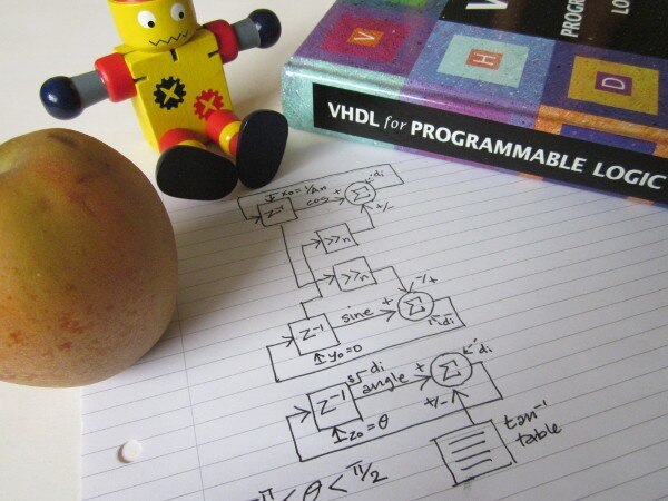
Here's how it looks in a fairly generic form.
(Today's apple is a Norfolk Royal Russet.)
Curiously, the method has some commonality with the computed iterative oscillators I looked at in a previous blog. Those oscillators relied on rotating a vector and this does too, however this time there are two rotations coupled together, the unit vector (represented by a pair of variables holding the sine and cosine) and that of the desired angle. As the angle is taken to zero, the 'unit' vector moves in step to the sine/cosine value for the starting angle. The neat thing about it is that the operations on the vector are in terms of powers of two, so multiplies become shifts. The overall process has some gain, so the cosine value at the start, instead of being one, is set to the inverse of the gain for the number of iterations being done so that the end result is unity [otherwise we'd need a multiplication at the end to scale it]. Of course, unlike the iterated oscillators, this one computes the sine from scratch for each sample, so there are no potential propagated errors from sample to sample, though obviously we need to concern ourselves with matters like the precision of the calculation: the control angle will come from a phase accumulator, in much the same way as with a sine table look-up.
Andraka's paper outlines three possible ways to implement the CORDIC processor, each with advantages and disadvantages. The natural way you'd think to do it, operating on words with one iteration per clock, unfortunately necessitates a barrel-shifter. That starts to get expensive in terms of both area (logic) and time, because of the delays through it, as the word length goes up. The simpler approach he gives is the bit-serial one. Here the variables are held in shift registers and the add or subtract is done one bit at a time. In this case, the barrel-shifting can be done by tapping off the shift registers. The big problem with this approach is simply the time it takes to do all the processing. Going the other way, he also points out that the fastest approach would be to unroll the iteration and have dedicated hardware for each cycle (this is the equivalent of in-lining a piece of recursive code). Interestingly, that helps with the shifts because there's no longer a need for components to do that, it all becomes a matter of wiring as the shift is fixed for a particular cycle. The table constants [the inverse tangents of the vector steps] also become wiring as the constant that is added to or subtracted from the angle for a particular iteration is a fixed value.
Because my sample rate is very low compared to the clock rate (100ksps vs 50MHz: I've got plenty of cycles before each result is needed) and I liked the apparent simplicity of the bit-serial approach, I chose to have a go at that one. [Note the word 'apparent' there. It didn't turn out quite so simple as it looked from simply drawing it quickly on a piece of paper.]
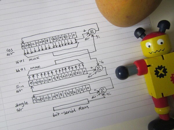
Data-flow Diagram
Here's how it's structured in the bit-serial form:
Coding and Testing
Here's the VHDL I concocted. As before, it hasn't been tested thoroughly nor had the output validated in anyway. It's an experiment: use it for real at your peril!
------------------------------------------------------------------
--    ***** waves_cordic_sine *****      --
--  15-bit CORDIC sine calculation in serial form (slow!)       --
------------------------------------------------------------------
-- JC 18th October 2019               --
------------------------------------------------------------------
-- Rev    Date         Comments         --
-- 01     18-Oct-2019            --
------------------------------------------------------------------
library ieee;
use ieee.std_logic_1164.all;
use ieee.std_logic_arith.all;
use ieee.std_logic_unsigned.all;

entity wave_cordic_con is port(
  clk_in:   in std_logic;        --- system clock in (50 MHz oscillator)
  --- DAC connections
  mcp4821_ncs: out std_logic;        --- DAC cs
  mcp4821_sck: out std_logic;        --- DAC sck
  mcp4821_sdi: out std_logic;        --- DAC sdi
  mcp4821_nldac: out std_logic;        --- DAC load
  --- misc control signals on evaluation board that it might be good to hold at fixed levels
  spi_cs:   out std_logic;        ---
  hold_n:   out std_logic;        ---
  sram_cen:  out std_logic;        ---
  sram_oen:  out std_logic;        ---
  sram_wen:  out std_logic;        ---
  uart_tx:  out std_logic);        ---
end wave_cordic_con;

architecture arch_wave_cordic of wave_cordic_con is
signal spi_send, spi_ncs, spi_ncs_del: std_logic;
signal spi_output_sr_bit_count: std_logic_vector (5 downto 0);
signal spi_output_sr: std_logic_vector (15 downto 0);
signal interval_count: std_logic_vector (8 downto 0);
signal acc_count: std_logic_vector (7 downto 0);
signal cordic_reset,cordic_enable, cordic_dir: std_logic;
signal cordic_count: std_logic_vector (7 downto 0);
signal adder_out: std_logic_vector (19 downto 0);
signal add_sub_1_out, add_sub_2_out, add_sub_3_out: std_logic_vector (0 downto 0);
signal mux_select: std_logic_vector (3 downto 0);
signal mux_count: std_logic_vector (3 downto 0);
---signal sine_tap_value, cos_tap_value: std_logic;
signal sine_tap_value, cos_tap_value: std_logic_vector (0 downto 0);
signal theta: std_logic_vector (19 downto 0);
signal phase_increment: std_logic_vector (19 downto 0);
signal sine_value: std_logic_vector (15 downto 0);
signal cos_value: std_logic_vector (15 downto 0);
signal angle_value: std_logic_vector (15 downto 0);
signal osc_reset: std_logic_vector (1 downto 0);
signal rom_out: std_logic_vector (0 downto 0);
signal carry_1_in, carry_2_in, carry_3_in: std_logic;
signal carry_1_out, carry_2_out, carry_3_out: std_logic;
signal sine_sign_extend, cos_sign_extend: std_logic;
signal sine_select: std_logic;

--- declare the adder/subractor and the table modules as components

component add_sub_module is
    port (
        DataA: in  std_logic_vector(0 downto 0);
        DataB: in  std_logic_vector(0 downto 0);
        Cin: in  std_logic;
        Add_Sub: in  std_logic;
        Result: out  std_logic_vector(0 downto 0);
        Cout: out  std_logic);
end component;

component rom_module is
    port (
        Address: in  std_logic_vector(7 downto 0);
        Q: out  std_logic_vector(0 downto 0));
end component;

component add_module is
    port (
        DataA: in  std_logic_vector(19 downto 0);
        DataB: in  std_logic_vector(19 downto 0);
        Result: out  std_logic_vector(19 downto 0));
end component;

begin
 wave_cordic_stuff: process (clk_in)
  begin
   if (clk_in'event and clk_in='1') then

    --- interval_count counts at the clock rate (50MHz)
    --- counts down by 500, so spi_send occurs every 10us (100kHz)

    if (interval_count(8 downto 0) = b"000000000") then     --- if zero
     interval_count(8 downto 0) <= b"111110011";      --- preset to 499
     spi_send <= '1';
    else
     interval_count(8 downto 0) <= interval_count(8 downto 0) - 1; --- count down
     spi_send <= '0';
    end if;

    --- spi ncs goes low when triggered by spi_send, goes hi again when bitcount reaches 31

    if (spi_send = '1') then
     spi_ncs <= '0';
    elsif (spi_output_sr_bit_count(5 downto 0) = b"111111") then
     spi_ncs <= '1';
    end if;

    spi_ncs_del <= spi_ncs;

    --- cordic reset occurs at end of spi cs
    --- this starts the CORDIC calculation for the next sine

    if (spi_ncs = '1' and spi_ncs_del = '0') then
     cordic_reset <= '1';
    else
     cordic_reset <= '0';
    end if;

    --- cordic enable and cordic count
    --- there are 15 cycles of 16 bits, so count goes to 240
    --- low half of count is the bit, high part is the cycle

    if (cordic_reset = '1') then
     cordic_enable <= '1';
---    elsif (cordic_count(7 downto 0) = b"00001111") then
    elsif (cordic_count(7 downto 0) = b"11011111") then
     cordic_enable <= '0';
    end if;

    if (cordic_enable = '1') then
     cordic_count(7 downto 0) <= cordic_count(7 downto 0) + 1;
    else
     cordic_count(7 downto 0) <= b"00000000";
    end if;

    --- spi output bit count only counts when enable spi cs is low

    if (spi_ncs = '0') then
     spi_output_sr_bit_count(5 downto 0) <= spi_output_sr_bit_count(5 downto 0) + 1;
    else
     spi_output_sr_bit_count(5 downto 0) <= b"000000";
    end if;

    --- phase accumulator
    --- (this is similar to what I had for the Taylor expansion)
    --- will run from -pi/2 to +pi/2 and generate the fourth and first quadrants of the sine

    if (spi_send = '1') then
     if (acc_count(7 downto 0) = b"0000000") then     --- if zero
      sine_select <= not sine_select;
      acc_count(7 downto 0) <= b"01100100";      --- preset to 100
      theta(19 downto 0) <= b"1_0_011011011110000001";  --- set to -pi/2
     else
      acc_count(7 downto 0) <= acc_count(7 downto 0) - 1;   --- count down
      theta(19 downto 0) <= adder_out(19 downto 0);    --- add increment to current phase
     end if;
    end if;

    --- CORDIC algorithm
    --- Implemented as bit-serial arithmetic (this is my choice for minimal hardware - not inherent in method).
    --- Each variable gets rotated out of shift register, with single bit at a time being presented
    --- to a 1-bit adder/subtractor, and the result shifted back in the other end.
    --- Cos start value is prescaled to save having to compensate with a
    --- multiplication at the end.
    --- angle_value is preset to the required phase, the algorithm then aims for an angle value of zero.
    --- Which side of zero we are on is easy to test for as it just entails looking at the resulting
    --- angle_value sign bit and using that to control whether to add or subtract on the next iteration.

    if (cordic_reset = '1') then
     sine_value(15 downto 0) <= b"0_0_00000000000000";   --- sin starts at 0
     cos_value(15 downto 0) <= b"0_1_00110110111000";   --- cos = 1/An (An is gain for n iterations)
---     cos_value(15 downto 0) <= b"0_0_10011011011101";   --- cos = 1/An (An is gain for n iterations)
---     cos_value(15 downto 0) <= b"0_0_01001101101110";   --- cos = 1/An (An is gain for n iterations)
     angle_value(15 downto 0) <= theta(19 downto 4);
    elsif (cordic_enable = '1') then
     cos_value(14 downto 0) <= cos_value(15 downto 1);   --- rotate right through add/sub
     cos_value(15) <= add_sub_1_out(0);
     sine_value(14 downto 0) <= sine_value(15 downto 1);   --- rotate right through add/sub
     sine_value(15) <= add_sub_2_out(0);
     angle_value(14 downto 0) <= angle_value(15 downto 1);  --- rotate right through add/sub
     angle_value(15) <= add_sub_3_out(0);
    end if;

    if (cordic_reset = '1') then
     cos_sign_extend <= '0';
     sine_sign_extend <= '0';
     cordic_dir <= theta(19);  --- initial direction depends on sign of angle
     carry_1_in <= not theta(19); --- sense of initial carry depends on whether next cycle is add or subtract
     carry_2_in <= theta(19);
     carry_3_in <= not theta(19);
    elsif (cordic_count(3 downto 0) = b"1111") then --- at end of word
     cos_sign_extend <= add_sub_1_out(0); --- sign of result is stored for next cycle
     sine_sign_extend <= add_sub_2_out(0); --- ... for use by sign-extension
     cordic_dir <= add_sub_3_out(0);   --- sign of angle determines add/sub for next cycle
     carry_1_in <= not add_sub_3_out(0);  --- set to no carry or no borrow at start
     carry_2_in <= add_sub_3_out(0);
     carry_3_in <= not add_sub_3_out(0);
    else
     carry_1_in <= carry_1_out;  --- whilst rotating, carry is from the last bit-add or bit-subtract
     carry_2_in <= carry_2_out;
     carry_3_in <= carry_3_out;
    end if;

    if (cordic_reset = '1') then
     mux_count <= b"0000";  ---
    elsif (cordic_count(3 downto 0) = b"1111") then
     mux_count <= cordic_count(7 downto 4) + 1;  ---
    elsif (mux_count(3 downto 0) /= b"1111") then
     mux_count <= mux_count + 1;
    end if;

    if (cordic_reset = '1') then
     mux_select <= b"0000";  --- s/r start 'tap' for next cycle
    elsif (cordic_reset = '1' or cordic_count(3 downto 0) = b"1111") then
     mux_select <= cordic_count(7 downto 4) + 1;  --- s/r start 'tap' for next cycle
    elsif (mux_count(3 downto 0) = b"1111") then
     mux_select <= b"1111";      --- ...selects sign extend instead for rest
    end if;

    --- spi output shift register

    if (spi_send = '1') then             --- load...
     if (sine_select = '1') then            ---
      spi_output_sr(10 downto 0) <= sine_value(14 downto 4);    ---  use sine
      spi_output_sr(11) <= not sine_value(15);       --- inverse of sign bit
     else
      spi_output_sr(10 downto 0) <= cos_value(14 downto 4);     --- use cos
      spi_output_sr(11) <= not cos_value(15);        --- inverse of sign bit
     end if;
     spi_output_sr(15 downto 12) <= b"0011";         ---   dac control bits
    elsif (spi_ncs = '0' and spi_output_sr_bit_count(1 downto 0) = b"11") then --- shift...
     spi_output_sr(15 downto 1) <= spi_output_sr(14 downto 0);    ---  the register contents
     spi_output_sr(0) <= '0';
    end if;
   end if;

   --- multiplexers to tap the sine and cos shift registers
   --- (as well as doing the shift, these deal with the sign-extend
   --- for 2's complement arithmetic)

   case mux_select(3 downto 0) is
    when b"0000" => sine_tap_value(0) <= sine_value(0);
    when b"0001" => sine_tap_value(0) <= sine_value(1);
    when b"0010" => sine_tap_value(0) <= sine_value(2);
    when b"0011" => sine_tap_value(0) <= sine_value(3);
    when b"0100" => sine_tap_value(0) <= sine_value(4);
    when b"0101" => sine_tap_value(0) <= sine_value(5);
    when b"0110" => sine_tap_value(0) <= sine_value(6);
    when b"0111" => sine_tap_value(0) <= sine_value(7);
    when b"1000" => sine_tap_value(0) <= sine_value(8);
    when b"1001" => sine_tap_value(0) <= sine_value(9);
    when b"1010" => sine_tap_value(0) <= sine_value(10);
    when b"1011" => sine_tap_value(0) <= sine_value(11);
    when b"1100" => sine_tap_value(0) <= sine_value(12);
    when b"1101" => sine_tap_value(0) <= sine_value(13);
    when b"1110" => sine_tap_value(0) <= sine_value(14);
    when b"1111" => sine_tap_value(0) <= sine_sign_extend;
    when others => sine_tap_value(0) <= sine_sign_extend;
   end case;

   case mux_select(3 downto 0) is
    when b"0000" => cos_tap_value(0) <= cos_value(0);
    when b"0001" => cos_tap_value(0) <= cos_value(1);
    when b"0010" => cos_tap_value(0) <= cos_value(2);
    when b"0011" => cos_tap_value(0) <= cos_value(3);
    when b"0100" => cos_tap_value(0) <= cos_value(4);
    when b"0101" => cos_tap_value(0) <= cos_value(5);
    when b"0110" => cos_tap_value(0) <= cos_value(6);
    when b"0111" => cos_tap_value(0) <= cos_value(7);
    when b"1000" => cos_tap_value(0) <= cos_value(8);
    when b"1001" => cos_tap_value(0) <= cos_value(9);
    when b"1010" => cos_tap_value(0) <= cos_value(10);
    when b"1011" => cos_tap_value(0) <= cos_value(11);
    when b"1100" => cos_tap_value(0) <= cos_value(12);
    when b"1101" => cos_tap_value(0) <= cos_value(13);
    when b"1110" => cos_tap_value(0) <= cos_value(14);
    when b"1111" => cos_tap_value(0) <= cos_sign_extend;
    when others => cos_tap_value(0) <= cos_sign_extend;
   end case;

   --- phase increment for testing

   phase_increment(19 downto 0) <= b"0_0_000010000000101011"; --- pi/100

   --- wiring the DAC I/O pins

   mcp4821_ncs <= spi_ncs;
   mcp4821_sck <= spi_output_sr_bit_count(1);
   mcp4821_sdi <= spi_output_sr(15);
   mcp4821_nldac <= '0';

   --- hold these device control pins at a fixed level to stop them flapping around

   spi_cs <= '1';
   hold_n <= '1';
   sram_cen <= '1';
   sram_oen <= '1';
   sram_wen <= '1';
   uart_tx <= '1';

  end process wave_cordic_stuff;

  --- instantiate the adder-subtractors, adder, and the ROM table holding the inverse tangent values

  add_sub_1: add_sub_module  --- cosine
   port map(
    DataA => cos_value(0 downto 0),
    DataB => sine_tap_value(0 downto 0),
    Cin => carry_1_in,
    Add_Sub => cordic_dir,
    Result => add_sub_1_out(0 downto 0),
    Cout => carry_1_out);

  add_sub_2: add_sub_module  --- sine
   port map(
    DataA => sine_value(0 downto 0),
    DataB => cos_tap_value(0 downto 0),
    Cin => carry_2_in,
    Add_Sub => not cordic_dir,
    Result => add_sub_2_out(0 downto 0),
    Cout => carry_2_out);

  add_sub_3: add_sub_module  ---angle
   port map(
    DataA => angle_value(0 downto 0),
    DataB => rom_out(0 downto 0),
    Cin => carry_3_in,
    Add_Sub => cordic_dir,
    Result => add_sub_3_out(0 downto 0),
    Cout => carry_3_out);

  rom_module1: rom_module   --- inverse-tangent table (bit serial, 256 bits, lsb first)
   port map(
    Address => cordic_count(7 downto 0),
    Q => rom_out(0 downto 0));

  add_1: add_module  --- phase accumulator calculation
   port map(
    DataA => theta(19 downto 0),
    DataB => phase_increment(19 downto 0),
    Result => adder_out(19 downto 0));
end arch_wave_cordic;
In places, it got a bit messy, particularly with the carry/borrows for the adder/subtracters and with the sign-extension to cope with the fact I was using a 2's complement representation. [The code doing the multiplexer control got hacked around a bit to make it work.]
The components I used IPExpress for were: a) a one-bit adder/subtracter with no registers and carries in and out,
The ROM initialisation file is here (simply save it as cordic.mem and hand it to IPExpress in the specification dialog for the part):
0
0
1
0
0
0
1
0
0
1
0
0
1
1
0
0
0
0
1
1
0
1
0
1
1
0
1
1
1
0
0
0
1
0
1
1
0
1
0
1
1
1
1
1
0
0
0
0
1
0
1
0
1
1
1
1
1
1
1
0
0
0
0
0
0
1
1
1
1
1
1
1
1
1
0
0
0
0
0
0
0
0
0
0
0
0
0
0
0
1
0
0
0
0
0
0
0
0
0
0
0
0
0
0
1
0
0
0
0
0
0
0
0
0
0
0
0
0
0
1
0
0
0
0
0
0
0
0
0
0
0
0
0
0
1
0
0
0
0
0
0
0
0
0
0
0
0
0
0
1
0
0
0
0
0
0
0
0
0
0
0
0
0
0
1
0
0
0
0
0
0
0
0
0
0
0
0
0
0
1
0
0
0
0
0
0
0
0
0
0
0
0
0
0
1
0
0
0
0
0
0
0
0
0
0
0
0
0
0
1
0
0
0
0
0
0
0
0
0
0
0
0
0
0
1
0
0
0
0
0
0
0
0
0
0
0
0
0
0
0
0
0
0
0
0
0
0
0
0
0
0
0
0
0
0
That table contains the inverse tangents of the sine/cos multipliers [0.5, 0.25, 0.125, ...] represented in the number format I chose for the arithmetic [S1.14 - one sign bit, one whole number, 14 bits of fraction].
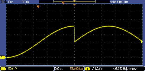
Here it is generating the fourth and first quadrants of a sine (left of screen) and the fourth and first quadrants of a cosine (right side of screen). I've got about 100 steps from -pi/2 to +pi/2, so the time is something like 10uS x 100 = 1ms for each. [It generates both sine and cosine together but, with only one DAC, I can only show them one at a time.]
Conclusion
When I first read about CORDIC it seemed like it might be very complicated, but essentially it's very simple and only involves elementary trigonometry. If you can get your head around what an inverse tangent is, you can do CORDIC. The complexity turned out to be in the rather fiddly and awkward control side for the particular way I've implemented it.
One lesson for me with these blogs is that implementing numerical methods like this on FPGA logic is a very good way to understand algorithms. Even if you don't quite understand at the start, by the time you've designed it and then got it working you'll have developed a pretty good idea of what it's doing.
A second useful reminder for me is that what works well on a processor doesn't necessarily work so well in programmable logic and vice versa.
A third point I've been thinking about is the complicated trade-offs that are inherent with algorithms and programmable logic. In this case, the CORDIC algorithm has the very nice feature that it doesn't require multipliers but that's traded against a fair amount of logic. If you don't have multipliers then it's very attractive, because of the logic you'd use to implement a fast multiplier with a long word length, but if you have an FPGA with multipliers and they're not otherwise utilised then it's not so simple and there might be better approaches. The problem is then, how do you know without an enclopedic knowledge of numerical methods and practical experience of implementation [even just this short experiment has shown me that how you implement CORDIC, for instance, will have a real effect on the logic resources consumed]?
[1] http://www.latticesemi.com/en/Products/DevelopmentBoardsAndKits/LatticeXP2Brevia2DevelopmentKit.aspx |
Top Comments