


|
Previous blogs: FPGA: Waves 2: Simple Sinewave
Introduction
I have a small Brevia 2 development board [1] from Lattice Semiconductor featuring one of their XP2-family FPGAs. I'm using it to explore, in a very simple, basic kind of way, digital signal generation and processing. This isn't a tutorial, just me experimenting and trying things out.
That experiment wasn't very successful. My attempt to recast it for the 18-bit multipliers in the Lattice device was a mess and didn't work properly. Although at first I got something like a sinewave from it, it was stuck on a single frequency and didn't respond to changing the parameters in the way it should have done.
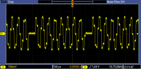
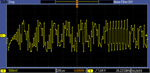
Fiddling about with it made for some very entertaining waveforms, though. Here's an example:
At that point I realised that I wasn't even implementing the correct form. I had implemented the simple Biquad oscillator thinking that it was the same as the oscillator given in that testbench, but it isn't: the one in the testbench has a couple of extra delays. I tried adding those, but had even less success - it now didn't do anything. I think that was down to my arithmetic and not handling the fixed-point stuff properly but, at this stage, I was getting a bit fed up with it so I decided to try implementing some other form of oscillator (partly because I was concerned that I might not be using the multiplier and subtracter components correctly).
Magic Roundabout Oscillator
This oscillator - 'Magic Roundabout' is my own name for it, it often gets called 'Magic Circle' - works on an alternative principle, namely modelling a rotating vector. Although the details are hidden and not obvious from simply looking at the code, essentially it's matrix multiplication where the matrix does rotation of a unit vector about the origin. [I found that out by reading about it - I wouldn't have puzzled it out for myself.] The number of multiplications needed can be reduced to two multiplies rather than the four you might expect and, though there are two multipliers, they take the same parameter, so simplifying the frequency control of it.
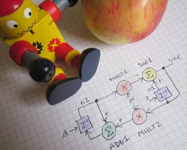
Here's a diagram of its form:
If you're not used to such diagrams, the boxes marked z^-1 are storage elements and latch their inputs at each sample time, so providing a single sample-period delay.
This oscillator has two state variables. One is the sine output, the other is almost the quadrature of that but, if I'm understanding it correctly, differs by the amount needed to drive the process forward (it's almost, but not quite, the cosine, but the difference from the true cosine will vary according to the frequency selected and the inaccuracy will get quite bad at the top end of the frequency range). A nice feature of it is that the frequency control parameter can be varied on a sample by sample basis [there's no previous history that would need to be adjusted], however I don't know if it remains constant-amplitude if you do that a lot.
Here's the VHDL (this is actually the code for the two-frequency test at the end).
------------------------------------------------------------------
--    ***** waves_magic *****       --
--  Test of MCP4821 DAC with sine wave from magic circle osc    --
------------------------------------------------------------------
-- JC 28th September 2019          --
------------------------------------------------------------------
-- Rev    Date         Comments         --
-- 01     28-Sept-2019            --
------------------------------------------------------------------
library ieee;
use ieee.std_logic_1164.all;
use ieee.std_logic_arith.all;
use ieee.std_logic_unsigned.all;
entity wave_test_con is port(
  clk_in:   in std_logic;        --- system clock in (50 MHz oscillator)
  --- DAC connections
  mcp4821_ncs: out std_logic;        --- DAC cs
  mcp4821_sck: out std_logic;        --- DAC sck
  mcp4821_sdi: out std_logic;        --- DAC sdi
  mcp4821_nldac: out std_logic;        --- DAC load
  --- misc control signals on evaluation board that it might be good to hold at fixed levels
  spi_cs:   out std_logic;        ---
  hold_n:   out std_logic;        ---
  sram_cen:  out std_logic;        ---
  sram_oen:  out std_logic;        ---
  sram_wen:  out std_logic;        ---
  uart_tx:  out std_logic);        ---

end wave_test_con;
architecture arch_wave_test of wave_test_con is
signal spi_send, spi_ncs, spi_ncs_del: std_logic;
---signal waveform_count: std_logic_vector (11 downto 0);
signal spi_output_sr_bit_count: std_logic_vector (5 downto 0);
signal spi_output_sr: std_logic_vector (15 downto 0);
signal interval_count: std_logic_vector (8 downto 0);
signal sample_count: std_logic_vector (15 downto 0);
signal sine_value: std_logic_vector (17 downto 0);
signal mult1_product: std_logic_vector (35 downto 0);
signal mult2_product: std_logic_vector (35 downto 0);
signal add_result: std_logic_vector (17 downto 0);
signal sub_result: std_logic_vector (17 downto 0);
signal n1: std_logic_vector (17 downto 0);
signal n2: std_logic_vector (17 downto 0);
signal osc_reset: std_logic_vector (1 downto 0);
signal alpha: std_logic_vector (17 downto 0);
--- declare the multiplier and the subtractor modules as components
component mult_module is
    port (
        DataA: in  std_logic_vector(17 downto 0);
        DataB: in  std_logic_vector(17 downto 0);
        Result: out  std_logic_vector(35 downto 0));
end component;
component subtract_module is
    port (
        DataA: in  std_logic_vector(17 downto 0);
        DataB: in  std_logic_vector(17 downto 0);
        Result: out  std_logic_vector(17 downto 0));
end component;
component adder_module is
    port (
        DataA: in  std_logic_vector(17 downto 0);
        DataB: in  std_logic_vector(17 downto 0);
        Result: out  std_logic_vector(17 downto 0));
end component;
begin
 wave_test_stuff: process (clk_in)
  begin
   if (clk_in'event and clk_in='1') then

    --- interval_count counts at the clock rate (50MHz)
    --- counts down by 500, so spi_send occurs every 10us (100kHz)
    if (interval_count(8 downto 0) = b"000000000") then     --- if zero
     interval_count(8 downto 0) <= b"111110011";      --- preset to 499
     spi_send <= '1';
    else
     interval_count(8 downto 0) <= interval_count(8 downto 0) - 1; --- count down
     spi_send <= '0';
    end if;
    --- spi ncs goes low when triggered by spi_send, goes hi again when bitcount reaches 31

    if (spi_send = '1') then
     spi_ncs <= '0';
    elsif (spi_output_sr_bit_count(5 downto 0) = b"111111") then
     spi_ncs <= '1';
    end if;

    spi_ncs_del <= spi_ncs;
    --- spi output bit count only counts when enable spi cs is low

    if (spi_ncs = '0') then
     spi_output_sr_bit_count(5 downto 0) <= spi_output_sr_bit_count(5 downto 0) + 1;
    else
     spi_output_sr_bit_count(5 downto 0) <= b"000000";
    end if;
    --- sample count
    if (spi_send = '1') then
     sample_count(15 downto 0) <= sample_count(15 downto 0) + 1;
     if(osc_reset(1 downto 0) /= b"10") then
      osc_reset <= osc_reset + 1;
     end if;
     if (sample_count(15) = '1') then
      alpha <= b"000000000110011100";  --- 25Hz
     else
      alpha <= b"000001000000010110";  --- 250Hz
     end if;
    end if;
    --- oscillator
    if (spi_send = '1') then
     if (osc_reset(0) = '1') then
      n1(17 downto 0) <= b"000000000000000000";
      n2(17 downto 0) <= b"000111111111110000";
     else
      n1(17 downto 0) <= sine_value(17 downto 0);
      n2(17 downto 0) <= add_result(17 downto 0);
     end if;
    end if;
    --- spi output shift register

    if (spi_send = '1') then             --- load...
     spi_output_sr(11 downto 0) <= sine_value(16 downto 5);     ---
---     spi_output_sr(11 downto 0) <= sine_value(11 downto 0);     ---
     spi_output_sr(11) <= not sine_value(17);     ---
     spi_output_sr(15 downto 12) <= b"0011";         ---   dac control bits
    elsif (spi_ncs = '0' and spi_output_sr_bit_count(1 downto 0) = b"11") then --- shift...
     spi_output_sr(15 downto 1) <= spi_output_sr(14 downto 0);    ---  the register contents
     spi_output_sr(0) <= '0';
    end if;
   end if;

   ---

   mcp4821_ncs <= spi_ncs;
   mcp4821_sck <= spi_output_sr_bit_count(1);
   mcp4821_sdi <= spi_output_sr(15);
   mcp4821_nldac <= '0';

   --- hold these device control pins at a fixed level to stop them flapping around
   spi_cs <= '1';
   hold_n <= '1';
   sram_cen <= '1';
   sram_oen <= '1';
   sram_wen <= '1';
   uart_tx <= '1';
  end process wave_test_stuff;

  --- instantiate the multipliers, adders and subtractors

  mult_module1: mult_module
   port map(
    DataA => alpha,
    DataB => n2(17 downto 0),
    Result => mult1_product(35 downto 0));

  mult_module2: mult_module
   port map(
    DataA => alpha,
    DataB => sine_value(17 downto 0),
    Result => mult2_product(35 downto 0));

  subtract_module1: subtract_module
   port map(
    DataA => n1(17 downto 0),
    DataB => mult1_product(35 downto 18),
    Result => sine_value(17 downto 0));
  adder_module1: adder_module
   port map(
    DataA =>  n2,
    DataB =>  mult2_product(35 downto 18),
    Result => add_result(17 downto 0));
end arch_wave_test;
In adddition to that code, I used the IPExpress tool in Diamond to create modules for a signed 18-bit multiplier, signed 18-bit adder, and signed 18-bit subtracter which were included in the project and which I then instantiated as components.
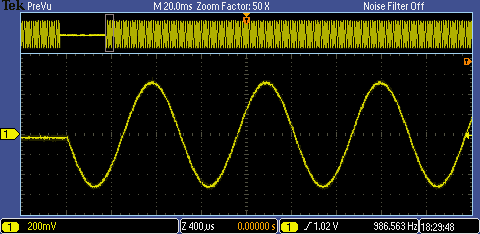
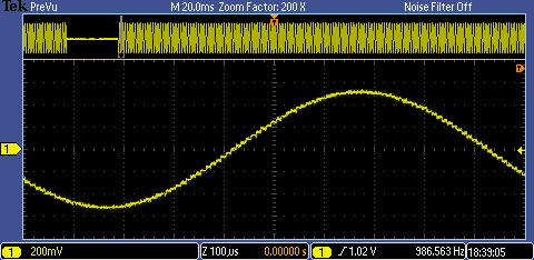
This time I was immediately more successful. Here's the DAC output for a 1kHz sinewave with a peak-to-peak amplitude of 1V (that's half the DAC range).
Here's a closer view of the sine - keep in mind that there's no reconstruction filter, so we expect to see the steps.
I ran that for about half an hour (about 1.8M cycles) and it didn't show any change of amplitude.
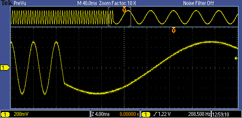
Here it is with the code adapted to switch between 250Hz and 25Hz on the fly. I ran that for about 10 minutes without seeing any change of amplitude, but the switch of frequency only occurs about once a second, so you'd need a much longer test to be very sure of it. I had a look at it later and the amplitude had increased slightly, so it looks like it does wander.
Conclusion
This has been an interesting diversion and I may come back to it later on, with a further look at some of the variations on these simple ideas that people have invented to get around the problem of dynamically controlling them, but for the moment I'm going to go back to using the table look-up approach as that easily allows me to manipulate frequency and phase without all the complications that come from changing an iterative process on the fly.
One thing that is evident from all this is that I need to improve my understanding of discrete-time theory and z transforms.
If you found this interesting and would like to see more blogs I've written, a list can be found here: jc2048 Blog Index
[1] http://www.latticesemi.com/en/Products/DevelopmentBoardsAndKits/LatticeXP2Brevia2DevelopmentKit.aspx |
Top Comments