element14 Community
element14 Community
    Register Log In
  • Site
  • Search
  • Log In Register
  • About Us
  • Community Hub
    Community Hub
    • What's New on element14
    • Feedback and Support
    • Benefits of Membership
    • Personal Blogs
    • Members Area
    • Achievement Levels
  • Learn
    Learn
    • Ask an Expert
    • eBooks
    • element14 presents
    • Learning Center
    • Tech Spotlight
    • STEM Academy
    • Webinars, Training and Events
    • Learning Groups
  • Technologies
    Technologies
    • 3D Printing
    • FPGA
    • Industrial Automation
    • Internet of Things
    • Power & Energy
    • Sensors
    • Technology Groups
  • Challenges & Projects
    Challenges & Projects
    • Design Challenges
    • element14 presents Projects
    • Project14
    • Arduino Projects
    • Raspberry Pi Projects
    • Project Groups
  • Products
    Products
    • Arduino
    • Avnet Boards Community
    • Dev Tools
    • Manufacturers
    • Multicomp Pro
    • Product Groups
    • Raspberry Pi
    • RoadTests & Reviews
  • Store
    Store
    • Visit Your Store
    • Choose another store...
      • Europe
      •  Austria (German)
      •  Belgium (Dutch, French)
      •  Bulgaria (Bulgarian)
      •  Czech Republic (Czech)
      •  Denmark (Danish)
      •  Estonia (Estonian)
      •  Finland (Finnish)
      •  France (French)
      •  Germany (German)
      •  Hungary (Hungarian)
      •  Ireland
      •  Israel
      •  Italy (Italian)
      •  Latvia (Latvian)
      •  
      •  Lithuania (Lithuanian)
      •  Netherlands (Dutch)
      •  Norway (Norwegian)
      •  Poland (Polish)
      •  Portugal (Portuguese)
      •  Romania (Romanian)
      •  Russia (Russian)
      •  Slovakia (Slovak)
      •  Slovenia (Slovenian)
      •  Spain (Spanish)
      •  Sweden (Swedish)
      •  Switzerland(German, French)
      •  Turkey (Turkish)
      •  United Kingdom
      • Asia Pacific
      •  Australia
      •  China
      •  Hong Kong
      •  India
      •  Korea (Korean)
      •  Malaysia
      •  New Zealand
      •  Philippines
      •  Singapore
      •  Taiwan
      •  Thailand (Thai)
      • Americas
      •  Brazil (Portuguese)
      •  Canada
      •  Mexico (Spanish)
      •  United States
      Can't find the country/region you're looking for? Visit our export site or find a local distributor.
  • Translate
  • Profile
  • Settings
FPGA
  • Technologies
  • More
FPGA
Blog Mini Elevator Arty S7 #4 - Programming with Vivado Design Suite
  • Blog
  • Forum
  • Documents
  • Quiz
  • Events
  • Polls
  • Files
  • Members
  • Mentions
  • Sub-Groups
  • Tags
  • More
  • Cancel
  • New
Join FPGA to participate - click to join for free!
  • Share
  • More
  • Cancel
Group Actions
  • Group RSS
  • More
  • Cancel
Engagement
  • Author Author: guillengap
  • Date Created: 11 Jun 2022 4:50 PM Date Created
  • Views 1666 views
  • Likes 10 likes
  • Comments 3 comments
  • arty-s7
  • RTL migration
  • MicroBlaze migration
  • xilinx
  • fpga
  • vivado
  • spartan-7
  • Spartan_Migration
Related
Recommended

Mini Elevator Arty S7 #4 - Programming with Vivado Design Suite

guillengap
guillengap
11 Jun 2022

Table of Contents

  • Introduction
  • Getting Started
  • Build and Wiring
  • Programming with Vivado Design Suite
  • Adding the PIR Motion Sensor
  • Experimenting with Automatic Sliding Door
  • Summary

**********************************************************************************************************************

Once we've wired the mini elevator circuit, it's time to program the Arty S7 board.

image

Finite State Machine

In this project, our timer moves between several different modes, for example: setting the time, then counting down. To handle these different modes, we use a Finite State Machine (FSM).

Finite state machines are one of the most widely used concepts in digital design. A finite state machine has a limited number of states with well-defined transitions between them. Simple real-world FSMs include elevators, traffic lights, and vending machines. For my timer design, I’ve drawn this:
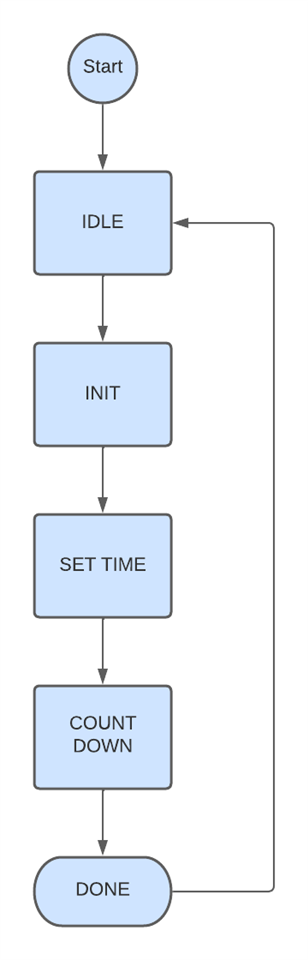
image

States

  • Idle - wait for the user to tell us what to do
  • Init - set initial values, such move up or down the elevator.
  • Set Time - set time delay of the stepper motor
  • Countdown - timer is running
  • Done - the elevator is moving up or moving down until the user activates the stop switch

Transitions

  • From Idle to Init - user presses control buttons: sw0 (move up or move down the elevator), and sw1 (activate the elevator or stoping it)
  • From Init to Set Time - automatically happens after one clock tick
  • From Set Time to Countdown - user presses control button
  • From Countdown to Done - after the timer reaches zero
  • From Done to Idle - after elevator is stoping

FSM Implementation

Now we have a design; we need to translate this into Verilog.  

I use what I learned in chapter 3 of this project as a reference, so I have created mini_elevator_arty project as shown below:

image

Now, I have created Arty-S7-50-Master.xdc constraints file as shown below:

image

Finally, I have created the file main.sv as shown in the image below:

image

We declare the input and output ports of the Arty S7 board as follows: a) the LEDs are used to verify if the elevator is active or not, b) the io0, io1, io2, and io3 ports take control of the stepper motor, c) the "sw" switch activates the up or down movement of the elevator, and d) the "en" button activates or stops the elevator.

module main (
    input wire logic clk,
    input wire logic sw,
    input wire logic en,
    output     logic [3:0] led,
    output     logic io0,
    output     logic io1,
    output     logic io2,
    output     logic io3            
    );

A register to track the elevator:

    logic light_set;  // active elevator: 0 = move down, 1 = move up

For this FSM of the elevator, I’m going to use a single process combining state change and behaviour:

    // finite state machine: state change & behavior
    enum {IDLE, INIT, FIRST_STEP, SECOND_STEP, THIRD_STEP, FOURTH_STEP, STOP} state;
    always_ff @(posedge clk) begin
        light_set = sw;                                                  
        case (state)
            IDLE: state <= INIT;
            INIT: begin
                state <= FIRST_STEP;
                light_set <= ~light_set;  // switch active light set
            end
            FIRST_STEP: begin
                if (cnt_phase == 0) begin
                    state <= SECOND_STEP;
                    cnt_phase <= DELAY;
                end else if (stb) cnt_phase <= cnt_phase - 1;           
            end
            SECOND_STEP: begin
                if (cnt_phase == 0) begin
                    state <= THIRD_STEP;
                    cnt_phase <= DELAY;
                end else if (stb) cnt_phase <= cnt_phase - 1;            
            end
            THIRD_STEP: begin
                if (cnt_phase == 0) begin
                    state <= FOURTH_STEP;
                    cnt_phase <= DELAY;
                end else if (stb) cnt_phase <= cnt_phase - 1;           
            end
            FOURTH_STEP: begin
                if (cnt_phase == 0) begin
                    state <= STOP;                    
                    cnt_phase <= DELAY;
                    light_set <= ~light_set;  // switch active light set
                end else if (stb) cnt_phase <= cnt_phase - 1;          
            end
            STOP: begin
                if (en == 1'b1)
                    state <= FIRST_STEP;
                else 
                    state <= STOP;
            end
            default: state <= STOP;
        endcase
    end

We control the LEDS and PORTS like so:

    // set LEDS based on active light set and state
    always_ff @(posedge clk) begin
        case (state)
            FIRST_STEP: begin
                if (light_set == 0) begin
                    led[0] = 1;
                    led[1] = 0;
                    led[2] = 0;
                    led[3] = 1;
                    io0 = 1;
                    io1 = 0;
                    io2 = 0;
                    io3 = 1;           
                end else if (light_set == 1) begin
                    led[0] = 0;
                    led[1] = 1;
                    led[2] = 0;
                    led[3] = 1;                    
                    io0 = 0;
                    io1 = 1;
                    io2 = 0;
                    io3 = 1;                                        
                end
            end        
        
            SECOND_STEP: begin
                if (light_set == 0) begin
                    led[0] = 1;
                    led[1] = 0;
                    led[2] = 1;
                    led[3] = 0;                    
                    io0 = 1;
                    io1 = 0;
                    io2 = 1;
                    io3 = 0;                                        
                end else if (light_set == 1) begin
                    led[0] = 0;
                    led[1] = 1;
                    led[2] = 1;
                    led[3] = 0;                    
                    io0 = 0;
                    io1 = 1;
                    io2 = 1;
                    io3 = 0;                                        
                end
            end

            THIRD_STEP: begin
                if (light_set == 0) begin
                    led[0] = 0;
                    led[1] = 1;
                    led[2] = 1;
                    led[3] = 0;                    
                    io0 = 0;
                    io1 = 1;
                    io2 = 1;
                    io3 = 0;                                        
                end else if (light_set == 1) begin
                    led[0] = 1;
                    led[1] = 0;
                    led[2] = 1;
                    led[3] = 0;                      
                    io0 = 1;
                    io1 = 0;
                    io2 = 1;
                    io3 = 0;                      
                end
            end
            FOURTH_STEP: begin
                if (light_set == 0) begin
                    led[0] = 0;
                    led[1] = 1;
                    led[2] = 0;
                    led[3] = 1;                   
                    io0 = 0;
                    io1 = 1;
                    io2 = 0;
                    io3 = 1;                                       
                end else if (light_set == 1) begin
                    led[0] = 1;
                    led[1] = 0;
                    led[2] = 0;
                    led[3] = 1;                    
                    io0 = 1;
                    io1 = 0;
                    io2 = 0;
                    io3 = 1;                                        
                end
            end

            STOP: begin
                if (light_set == 0) begin
                    led[0] = 0;
                    led[1] = 0;
                    led[2] = 0;
                    led[3] = 0;                   
                    io0 = 0;
                    io1 = 0;
                    io2 = 0;
                    io3 = 0;                                       
                end else if (light_set == 1) begin
                    led[0] = 0;
                    led[1] = 0;
                    led[2] = 0;
                    led[3] = 0;                    
                    io0 = 0;
                    io1 = 0;
                    io2 = 0;
                    io3 = 0;                                        
                end
            end          
        endcase
    end

I have programmed a 20 ms delay in the stepper motor by using a strobe light. My finished main.sv file looks like this

`timescale 1ns / 1ps
//////////////////////////////////////////////////////////////////////////////////
// AUTHOR:GUILLERMO PEREZ GUILLEN
//////////////////////////////////////////////////////////////////////////////////

module main (
    input wire logic clk,
    input wire logic sw,
    input wire logic en,
    output     logic [3:0] led,
    output     logic io0,
    output     logic io1,
    output     logic io2,
    output     logic io3            
    );

    // stepper motor phases 
    localparam DELAY = 1;

    logic [3:0] cnt_phase;  // 4-bit allows up to 15 second phase
    logic light_set;  // active elevator: 0 = move down, 1 = move up

    // generate 20 milliseconds strobe  
    localparam DIV_BY = 27'd500_000;  // 500000 -> 0.020 sec      
    logic stb;
    logic [$clog2(DIV_BY)-1:0] cnt_stb;
    always_ff @(posedge clk) begin
        if (cnt_stb != DIV_BY-1) begin
            stb <= 0;
            cnt_stb <= cnt_stb + 1;
        end else begin
            stb <= 1;
            cnt_stb <= 0;
        end
    end

    // finite state machine: state change & behavior
    enum {IDLE, INIT, FIRST_STEP, SECOND_STEP, THIRD_STEP, FOURTH_STEP, STOP} state;
    always_ff @(posedge clk) begin
        light_set = sw;                                                  
        case (state)
            IDLE: state <= INIT;
            INIT: begin
                state <= FIRST_STEP;
                light_set <= ~light_set;  // switch active light set
            end
            FIRST_STEP: begin
                if (cnt_phase == 0) begin
                    state <= SECOND_STEP;
                    cnt_phase <= DELAY;
                end else if (stb) cnt_phase <= cnt_phase - 1;           
            end
            SECOND_STEP: begin
                if (cnt_phase == 0) begin
                    state <= THIRD_STEP;
                    cnt_phase <= DELAY;
                end else if (stb) cnt_phase <= cnt_phase - 1;            
            end
            THIRD_STEP: begin
                if (cnt_phase == 0) begin
                    state <= FOURTH_STEP;
                    cnt_phase <= DELAY;
                end else if (stb) cnt_phase <= cnt_phase - 1;           
            end
            FOURTH_STEP: begin
                if (cnt_phase == 0) begin
                    state <= STOP;                    
                    cnt_phase <= DELAY;
                    light_set <= ~light_set;  // switch active light set
                end else if (stb) cnt_phase <= cnt_phase - 1;          
            end
            STOP: begin
                if (en == 1'b1)
                    state <= FIRST_STEP;
                else 
                    state <= STOP;
            end
            default: state <= STOP;
        endcase
    end

    // set LEDS based on active light set and state
    always_ff @(posedge clk) begin
        case (state)
            FIRST_STEP: begin
                if (light_set == 0) begin
                    led[0] = 1;
                    led[1] = 0;
                    led[2] = 0;
                    led[3] = 1;
                    io0 = 1;
                    io1 = 0;
                    io2 = 0;
                    io3 = 1;           
                end else if (light_set == 1) begin
                    led[0] = 0;
                    led[1] = 1;
                    led[2] = 0;
                    led[3] = 1;                    
                    io0 = 0;
                    io1 = 1;
                    io2 = 0;
                    io3 = 1;                                        
                end
            end        
        
            SECOND_STEP: begin
                if (light_set == 0) begin
                    led[0] = 1;
                    led[1] = 0;
                    led[2] = 1;
                    led[3] = 0;                    
                    io0 = 1;
                    io1 = 0;
                    io2 = 1;
                    io3 = 0;                                        
                end else if (light_set == 1) begin
                    led[0] = 0;
                    led[1] = 1;
                    led[2] = 1;
                    led[3] = 0;                    
                    io0 = 0;
                    io1 = 1;
                    io2 = 1;
                    io3 = 0;                                        
                end
            end

            THIRD_STEP: begin
                if (light_set == 0) begin
                    led[0] = 0;
                    led[1] = 1;
                    led[2] = 1;
                    led[3] = 0;                    
                    io0 = 0;
                    io1 = 1;
                    io2 = 1;
                    io3 = 0;                                        
                end else if (light_set == 1) begin
                    led[0] = 1;
                    led[1] = 0;
                    led[2] = 1;
                    led[3] = 0;                      
                    io0 = 1;
                    io1 = 0;
                    io2 = 1;
                    io3 = 0;                      
                end
            end
            FOURTH_STEP: begin
                if (light_set == 0) begin
                    led[0] = 0;
                    led[1] = 1;
                    led[2] = 0;
                    led[3] = 1;                   
                    io0 = 0;
                    io1 = 1;
                    io2 = 0;
                    io3 = 1;                                       
                end else if (light_set == 1) begin
                    led[0] = 1;
                    led[1] = 0;
                    led[2] = 0;
                    led[3] = 1;                    
                    io0 = 1;
                    io1 = 0;
                    io2 = 0;
                    io3 = 1;                                        
                end
            end

            STOP: begin
                if (light_set == 0) begin
                    led[0] = 0;
                    led[1] = 0;
                    led[2] = 0;
                    led[3] = 0;                   
                    io0 = 0;
                    io1 = 0;
                    io2 = 0;
                    io3 = 0;                                       
                end else if (light_set == 1) begin
                    led[0] = 0;
                    led[1] = 0;
                    led[2] = 0;
                    led[3] = 0;                    
                    io0 = 0;
                    io1 = 0;
                    io2 = 0;
                    io3 = 0;                                        
                end
            end          
        endcase
    end
endmodule

We need some constraints. Save the following as Arty-S7-50-Master.xdc

## Configuration options, can be used for all designs
set_property BITSTREAM.CONFIG.CONFIGRATE 50 [current_design]
set_property CONFIG_VOLTAGE 3.3 [current_design]
set_property CFGBVS VCCO [current_design]
set_property BITSTREAM.CONFIG.SPI_BUSWIDTH 4 [current_design]
set_property CONFIG_MODE SPIx4 [current_design]

## SW3 is assigned to a pin M5 in the 1.35v bank. This pin can also be used as
## the VREF for BANK 34. To ensure that SW3 does not define the reference voltage
## and to be able to use this pin as an ordinary I/O the following property must
## be set to enable an internal VREF for BANK 34. Since a 1.35v supply is being
## used the internal reference is set to half that value (i.e. 0.675v). Note that
## this property must be set even if SW3 is not used in the design.
set_property INTERNAL_VREF 0.675 [get_iobanks 34]

## Clock Signals
set_property -dict { PACKAGE_PIN R2    IOSTANDARD SSTL135 } [get_ports { clk }]; #IO_L12P_T1_MRCC_34 Sch=ddr3_clk[200]
create_clock -add -name sys_clk_pin -period 10.000 -waveform {0 5.000}  [get_ports { clk }];

## LEDs
set_property -dict { PACKAGE_PIN E18   IOSTANDARD LVCMOS33 } [get_ports { led[0] }]; #IO_L16N_T2_A27_15 Sch=led[2]
set_property -dict { PACKAGE_PIN F13   IOSTANDARD LVCMOS33 } [get_ports { led[1] }]; #IO_L17P_T2_A26_15 Sch=led[3]
set_property -dict { PACKAGE_PIN E13   IOSTANDARD LVCMOS33 } [get_ports { led[2] }]; #IO_L17N_T2_A25_15 Sch=led[4]
set_property -dict { PACKAGE_PIN H15   IOSTANDARD LVCMOS33 } [get_ports { led[3] }]; #IO_L18P_T2_A24_15 Sch=led[5]

## ChipKit Outer Digital Header
set_property -dict { PACKAGE_PIN L13   IOSTANDARD LVCMOS33 } [get_ports { io0 }]; #IO_0_14 Sch=ck_io[0]
set_property -dict { PACKAGE_PIN N13   IOSTANDARD LVCMOS33 } [get_ports { io1 }]; #IO_L6N_T0_D08_VREF_14   Sch=ck_io[1]
set_property -dict { PACKAGE_PIN L16   IOSTANDARD LVCMOS33 } [get_ports { io2 }]; #IO_L3N_T0_DQS_EMCCLK_14 Sch=ck_io[2]
set_property -dict { PACKAGE_PIN R14   IOSTANDARD LVCMOS33 } [get_ports { io3 }]; #IO_L13P_T2_MRCC_14      Sch=ck_io[3]

## Switches
set_property -dict { PACKAGE_PIN H14   IOSTANDARD LVCMOS33 } [get_ports { sw }]; #IO_L20N_T3_A19_15 Sch=sw[0]
set_property -dict { PACKAGE_PIN H18   IOSTANDARD LVCMOS33 } [get_ports { en }]; #IO_L21P_T3_DQS_15 Sch=sw[1]

Testing the System

Below I show you a video of how this project works.

You don't have permission to edit metadata of this video.
Edit media
x
image
Upload Preview
image

  • Sign in to reply

Top Comments

  • 14rhb
    14rhb over 3 years ago +1
    This a really fun project - well done. It makes a great reference example for anyone trying to learn about this technology: the Vivado side including XDC setup, a real example of FSM and a decent amount…
  • dang74
    dang74 over 3 years ago +1
    So cool to see the elevator in action.
  • dang74
    dang74 over 3 years ago

    So cool to see the elevator in action.

    • Cancel
    • Vote Up +1 Vote Down
    • Sign in to reply
    • More
    • Cancel
  • guillengap
    guillengap over 3 years ago in reply to 14rhb

    Thanks for your comment! I try to make things as simple as I can, more elegant, and easier to understand... some others try the opposite, and their slogan is: Why easy if it can be difficult? Thumbsup

    • Cancel
    • Vote Up 0 Vote Down
    • Sign in to reply
    • More
    • Cancel
  • 14rhb
    14rhb over 3 years ago

    This a really fun project - well done. It makes a great reference example for anyone trying to learn about this technology: the Vivado side including XDC setup, a real example of FSM and a decent amount of Verilog. Adding Spongebob... Smiley

    • Cancel
    • Vote Up +1 Vote Down
    • Sign in to reply
    • More
    • Cancel
element14 Community

element14 is the first online community specifically for engineers. Connect with your peers and get expert answers to your questions.

  • Members
  • Learn
  • Technologies
  • Challenges & Projects
  • Products
  • Store
  • About Us
  • Feedback & Support
  • FAQs
  • Terms of Use
  • Privacy Policy
  • Legal and Copyright Notices
  • Sitemap
  • Cookies

An Avnet Company © 2025 Premier Farnell Limited. All Rights Reserved.

Premier Farnell Ltd, registered in England and Wales (no 00876412), registered office: Farnell House, Forge Lane, Leeds LS12 2NE.

ICP 备案号 10220084.

Follow element14

  • X
  • Facebook
  • linkedin
  • YouTube