


Table of Contents
- Introduction
- Getting Started
- Build and Wiring
- Programming with Vivado Design Suite
- Adding the PIR Motion Sensor
- Experimenting with Automatic Sliding Door
- Summary
**********************************************************************************************************************
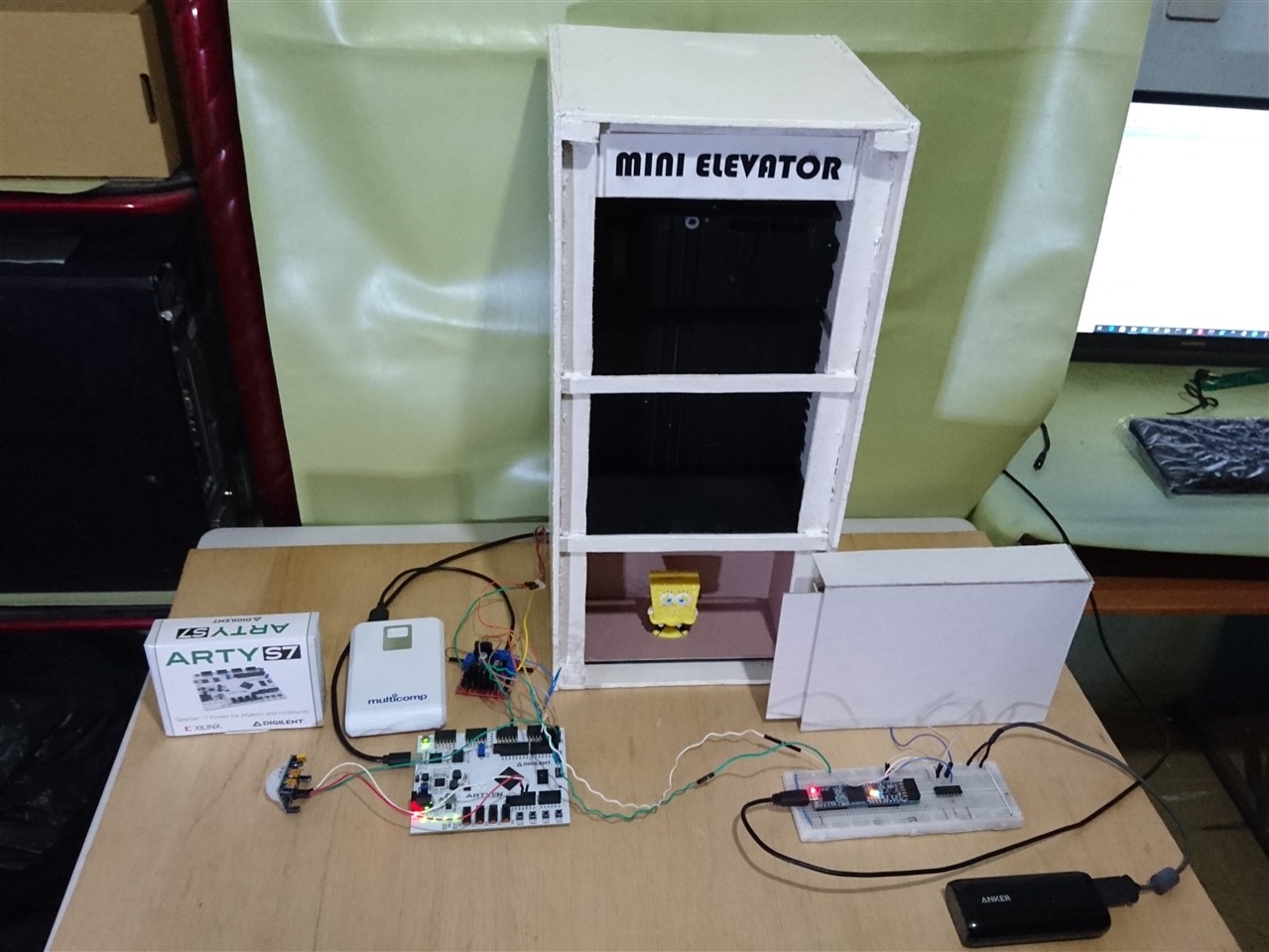
In this blog I am going to experiment with an automatic sliding door. I explored several solutions and in the end I decided on the one that I show in this chapter and hat I describe below:
- The Arty S7 board controls the movement of the cabin.
- The CMOD S7 board controls the automatic sliding door.
- The Arty S7 board is connected to the CMOD S7 board to notify its status.
- When the cabin moves up or down, the automatic sliding door is locked.
- When the cabin is stopped at the first floor, then the automatic sliding door can be opened or closed for users to enter or exit.
Automatic Sliding Door Design
This device was built from the reuse of an old CD player. In the end, I disassembled the electronic part, removed the locks and only the sliding tray and the CD motor remained.
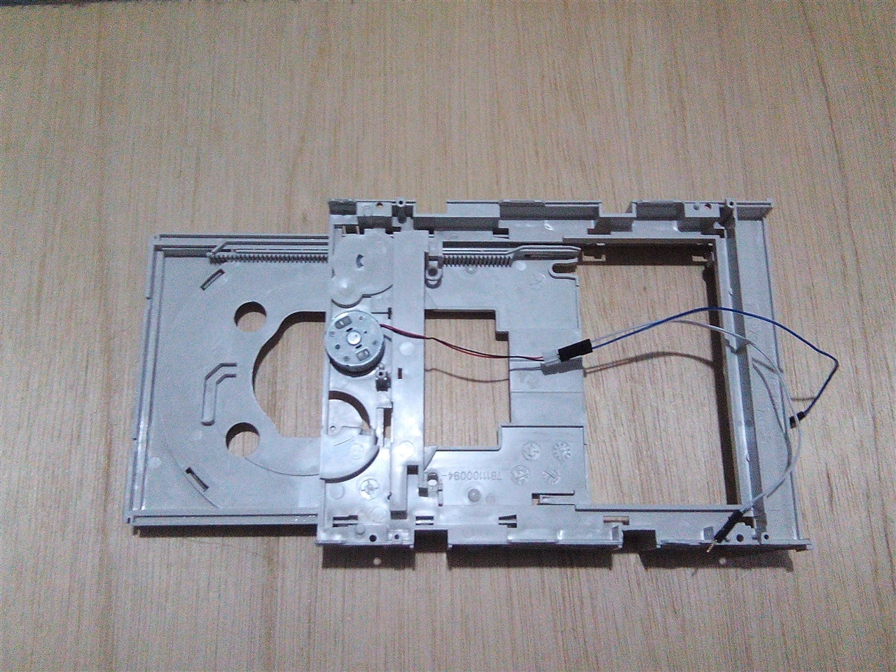
I covered the automatic sliding door prototype with white cardboard and glued it with silicone. Below I show you an image when the sliding door is closed.

Below I show you the open sliding door. I also had to remove some plastic to achieve free movement of the sliding door.

CMOD S7 Board Programming

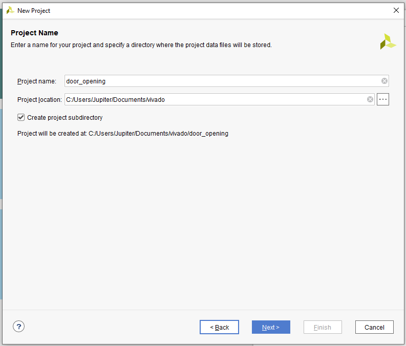
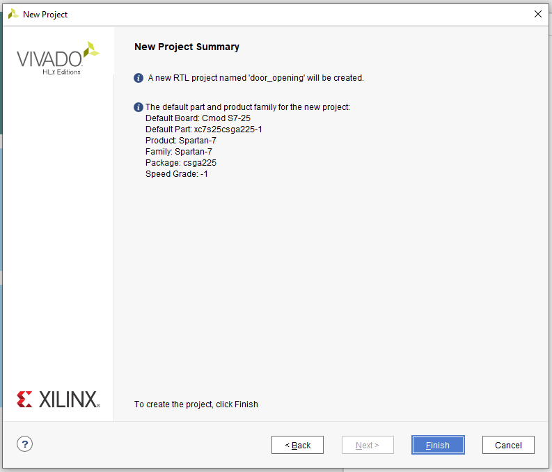
I used the example used in chapter 2 of this tutorial as a reference, so the name of the project is door_opening.
Then select the CMOD S7 25 board.
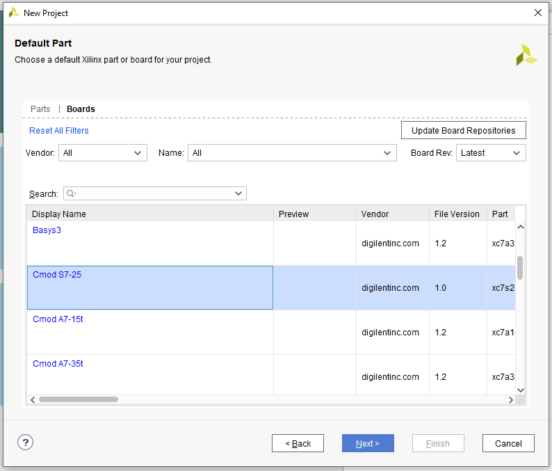
Finally, we verify the project data and click finish.
I have created the file door_opening.sv and the finished file looks like this
`timescale 1ns / 1ps
//////////////////////////////////////////////////////////////////////////////////
// AUTHOR:GUILLERMO PEREZ GUILLEN
//////////////////////////////////////////////////////////////////////////////////

module door_opening(
    input clk,
    input wire logic pio1,
    input wire logic btn0,
    input wire logic btn1,
    output logic pio2,
    output logic pio3,
    output logic led0,
    output logic led1
    );

    always_comb begin
        if (pio1 == 1 && btn0 == 1) begin // open the door
            pio2 = 0;
            pio3 = 1;
            led0 = 1;
            led1 = 0;
        end else if (pio1 == 1 && btn1 == 1) begin // close the door
            pio2 = 1;
            pio3 = 0;
            led0 = 0;
            led1 = 1;
        end else begin
            pio2 = 0;
            pio3 = 0;
            led0 = 0;
            led1 = 0;
        end
    end
endmodule
We need some constraints. Save the following as Cmod-S7-25-Master.xdc
## 12 MHz System Clock
set_property -dict { PACKAGE_PIN M9    IOSTANDARD LVCMOS33 } [get_ports { clk }]; #IO_L13P_T2_MRCC_14 Sch=gclk
create_clock -add -name sys_clk_pin -period 83.33 -waveform {0 41.66} [get_ports { clk }];

## 4 LEDs
set_property -dict { PACKAGE_PIN E2    IOSTANDARD LVCMOS33 } [get_ports { led0 }]; #IO_L8P_T1_34 Sch=led[1]
set_property -dict { PACKAGE_PIN K1    IOSTANDARD LVCMOS33 } [get_ports { led1 }]; #IO_L16P_T2_34 Sch=led[2

## Dedicated Digital I/O on the PIO Headers
set_property -dict { PACKAGE_PIN L1    IOSTANDARD LVCMOS33 } [get_ports { pio1 }]; #IO_L18N_T2_34 Sch=pio[01]
set_property -dict { PACKAGE_PIN M4    IOSTANDARD LVCMOS33 } [get_ports { pio2 }]; #IO_L19P_T3_34 Sch=pio[02]
set_property -dict { PACKAGE_PIN M3    IOSTANDARD LVCMOS33 } [get_ports { pio3 }]; #IO_L19N_T3_VREF_34 Sch=pio[03]

## Push Buttons
set_property -dict { PACKAGE_PIN D2    IOSTANDARD LVCMOS33 } [get_ports { btn0 }]; #IO_L6P_T0_34 Sch=btn[0]
set_property -dict { PACKAGE_PIN D1    IOSTANDARD LVCMOS33 } [get_ports { btn1 }]; #IO_L6N_T0_VREF_34 Sch=btn[1]
How does it work?
- When pio1 is equal to zero, the automatic sliding door is locked.
- When pio1 is equal to one, the automatic sliding door can be opened by pressing the btn0 button.
- When pio1 is equal to one, the automatic sliding door can be closed by pressing the btn1 button.
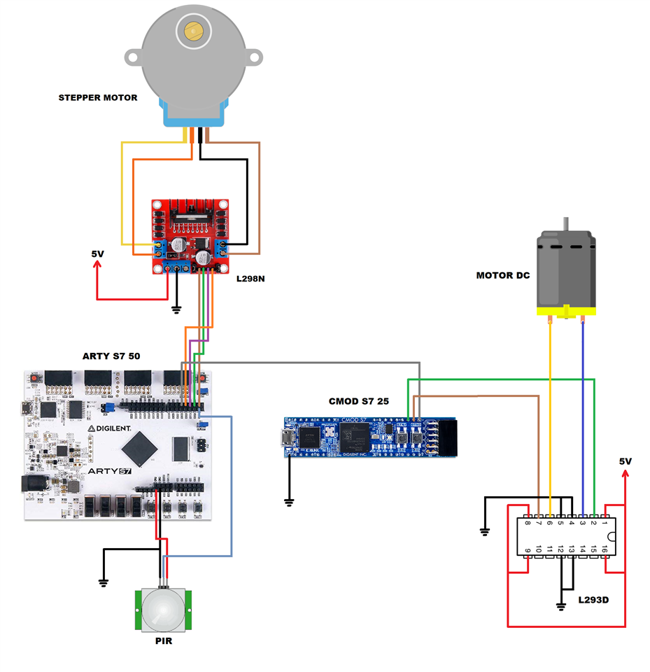
Schematic Diagram
With the addition of the CMOD S7 board, the L293D driver and the automatic sliding door motor CD, the final schematic diagram looks like this:
Arty S7 Board Programming
Since we have added new devices to the original design of the Mini Elevator Arty S7, the codes of the "mini_elevator_arty" project also need some changes. Below I show you how the main.sv code looks:
`timescale 1ns / 1ps
//////////////////////////////////////////////////////////////////////////////////
// AUTHOR:GUILLERMO PEREZ GUILLEN
//////////////////////////////////////////////////////////////////////////////////

module main (
    input wire logic clk,
    input wire logic sw,
    input wire logic en,
    output     logic [3:0] led,
    output     logic io0,
    output     logic io1,
    output     logic io2,
    output     logic io3,
    output     logic io4    // door enable
    );

    // stepper motor phases
    localparam DELAY = 1;

    logic [3:0] cnt_phase;  // 4-bit allows up to 15 second phase
    logic light_set;  // active elevator: 0 = move down, 1 = move up

    // generate 20 milliseconds strobe
    localparam DIV_BY = 27'd500_000;  // 500000 -> 0.020 sec
    logic stb;
    logic [$clog2(DIV_BY)-1:0] cnt_stb;
    always_ff @(posedge clk) begin
        if (cnt_stb != DIV_BY-1) begin
            stb <= 0;
            cnt_stb <= cnt_stb + 1;
        end else begin
            stb <= 1;
            cnt_stb <= 0;
        end
    end

    // finite state machine: state change & behavior
    enum {IDLE, INIT, FIRST_STEP, SECOND_STEP, THIRD_STEP, FOURTH_STEP, STOP} state;
    always_ff @(posedge clk) begin
        light_set = sw;
        case (state)
            IDLE: state <= INIT;
            INIT: begin
                state <= FIRST_STEP;
                light_set <= ~light_set;  // switch active light set
            end
            FIRST_STEP: begin
                if (cnt_phase == 0) begin
                    state <= SECOND_STEP;
                    cnt_phase <= DELAY;
                end else if (stb) cnt_phase <= cnt_phase - 1;
            end
            SECOND_STEP: begin
                if (cnt_phase == 0) begin
                    state <= THIRD_STEP;
                    cnt_phase <= DELAY;
                end else if (stb) cnt_phase <= cnt_phase - 1;
            end
            THIRD_STEP: begin
                if (cnt_phase == 0) begin
                    state <= FOURTH_STEP;
                    cnt_phase <= DELAY;
                end else if (stb) cnt_phase <= cnt_phase - 1;
            end
            FOURTH_STEP: begin
                if (cnt_phase == 0) begin
                    state <= STOP;
                    cnt_phase <= DELAY;
                    light_set <= ~light_set;  // switch active light set
                end else if (stb) cnt_phase <= cnt_phase - 1;
            end
            STOP: begin
                if (en == 1'b1)
                    state <= FIRST_STEP;
                else
                    state <= STOP;
            end
            default: state <= STOP;
        endcase
    end

    // set LEDS based on active light set and state
    always_ff @(posedge clk) begin
        case (state)
            FIRST_STEP: begin
                if (light_set == 0) begin
                    led[0] = 1;
                    led[1] = 0;
                    led[2] = 0;
                    led[3] = 1;
                    io0 = 1;
                    io1 = 0;
                    io2 = 0;
                    io3 = 1;
                    io4 = 0; // door disable
                end else if (light_set == 1) begin
                    led[0] = 0;
                    led[1] = 1;
                    led[2] = 0;
                    led[3] = 1;
                    io0 = 0;
                    io1 = 1;
                    io2 = 0;
                    io3 = 1;
                    io4 = 0; // door disable
                end
            end

            SECOND_STEP: begin
                if (light_set == 0) begin
                    led[0] = 1;
                    led[1] = 0;
                    led[2] = 1;
                    led[3] = 0;
                    io0 = 1;
                    io1 = 0;
                    io2 = 1;
                    io3 = 0;
                    io4 = 0; // door disable
                end else if (light_set == 1) begin
                    led[0] = 0;
                    led[1] = 1;
                    led[2] = 1;
                    led[3] = 0;
                    io0 = 0;
                    io1 = 1;
                    io2 = 1;
                    io3 = 0;
                    io4 = 0; // door disable
                end
            end

            THIRD_STEP: begin
                if (light_set == 0) begin
                    led[0] = 0;
                    led[1] = 1;
                    led[2] = 1;
                    led[3] = 0;
                    io0 = 0;
                    io1 = 1;
                    io2 = 1;
                    io3 = 0;
                    io4 = 0; // door disable
                end else if (light_set == 1) begin
                    led[0] = 1;
                    led[1] = 0;
                    led[2] = 1;
                    led[3] = 0;
                    io0 = 1;
                    io1 = 0;
                    io2 = 1;
                    io3 = 0;
                    io4 = 0; // door disable
                end
            end
            FOURTH_STEP: begin
                if (light_set == 0) begin
                    led[0] = 0;
                    led[1] = 1;
                    led[2] = 0;
                    led[3] = 1;
                    io0 = 0;
                    io1 = 1;
                    io2 = 0;
                    io3 = 1;
                    io4 = 0; // door disable
                end else if (light_set == 1) begin
                    led[0] = 1;
                    led[1] = 0;
                    led[2] = 0;
                    led[3] = 1;
                    io0 = 1;
                    io1 = 0;
                    io2 = 0;
                    io3 = 1;
                    io4 = 0; // door disable
                end
            end

            STOP: begin
                if (light_set == 0) begin
                    led[0] = 0;
                    led[1] = 0;
                    led[2] = 0;
                    led[3] = 0;
                    io0 = 0;
                    io1 = 0;
                    io2 = 0;
                    io3 = 0;
                    io4 = 1; // door enable
                end else if (light_set == 1) begin
                    led[0] = 0;
                    led[1] = 0;
                    led[2] = 0;
                    led[3] = 0;
                    io0 = 0;
                    io1 = 0;
                    io2 = 0;
                    io3 = 0;
                    io4 = 1; // door enable
                end
            end
        endcase
    end
endmodule
And the Arty-S7-50-Master.xdc file looks like this:
## Configuration options, can be used for all designs
set_property BITSTREAM.CONFIG.CONFIGRATE 50 [current_design]
set_property CONFIG_VOLTAGE 3.3 [current_design]
set_property CFGBVS VCCO [current_design]
set_property BITSTREAM.CONFIG.SPI_BUSWIDTH 4 [current_design]
set_property CONFIG_MODE SPIx4 [current_design]

## SW3 is assigned to a pin M5 in the 1.35v bank. This pin can also be used as
## the VREF for BANK 34. To ensure that SW3 does not define the reference voltage
## and to be able to use this pin as an ordinary I/O the following property must
## be set to enable an internal VREF for BANK 34. Since a 1.35v supply is being
## used the internal reference is set to half that value (i.e. 0.675v). Note that
## this property must be set even if SW3 is not used in the design.
set_property INTERNAL_VREF 0.675 [get_iobanks 34]

## Clock Signals
set_property -dict { PACKAGE_PIN R2    IOSTANDARD SSTL135 } [get_ports { clk }]; #IO_L12P_T1_MRCC_34 Sch=ddr3_clk[200]
create_clock -add -name sys_clk_pin -period 10.000 -waveform {0 5.000}  [get_ports { clk }];

## LEDs
set_property -dict { PACKAGE_PIN E18   IOSTANDARD LVCMOS33 } [get_ports { led[0] }]; #IO_L16N_T2_A27_15 Sch=led[2]
set_property -dict { PACKAGE_PIN F13   IOSTANDARD LVCMOS33 } [get_ports { led[1] }]; #IO_L17P_T2_A26_15 Sch=led[3]
set_property -dict { PACKAGE_PIN E13   IOSTANDARD LVCMOS33 } [get_ports { led[2] }]; #IO_L17N_T2_A25_15 Sch=led[4]
set_property -dict { PACKAGE_PIN H15   IOSTANDARD LVCMOS33 } [get_ports { led[3] }]; #IO_L18P_T2_A24_15 Sch=led[5]

## ChipKit Outer Digital Header
set_property -dict { PACKAGE_PIN L13   IOSTANDARD LVCMOS33 } [get_ports { io0 }]; #IO_0_14 Sch=ck_io[0]
set_property -dict { PACKAGE_PIN N13   IOSTANDARD LVCMOS33 } [get_ports { io1 }]; #IO_L6N_T0_D08_VREF_14   Sch=ck_io[1]
set_property -dict { PACKAGE_PIN L16   IOSTANDARD LVCMOS33 } [get_ports { io2 }]; #IO_L3N_T0_DQS_EMCCLK_14 Sch=ck_io[2]
set_property -dict { PACKAGE_PIN R14   IOSTANDARD LVCMOS33 } [get_ports { io3 }]; #IO_L13P_T2_MRCC_14      Sch=ck_io[3]
set_property -dict { PACKAGE_PIN T14   IOSTANDARD LVCMOS33 } [get_ports { io4 }]; #IO_L13N_T2_MRCC_14      Sch=ck_io[4]

## ChipKit Inner Digital Header
## Note: these pins are shared with PMOD Headers JC and JD and cannot be used at the same time as the applicable PMOD interface(s)
set_property -dict { PACKAGE_PIN U11   IOSTANDARD LVCMOS33 } [get_ports { io26 }]; #IO_L24P_T3_A01_D17_14        Sch=jd10/ck_io[26]

## Switches
set_property -dict { PACKAGE_PIN H14   IOSTANDARD LVCMOS33 } [get_ports { sw }]; #IO_L20N_T3_A19_15 Sch=sw[0]
set_property -dict { PACKAGE_PIN H18   IOSTANDARD LVCMOS33 } [get_ports { en }]; #IO_L21P_T3_DQS_15 Sch=sw[1]
Testing the Automatic Sliding Door
Below I show you a basic test of this sliding door, it is necessary to make sure that there are no obstructions and that everything is working according to plan.
Everything is fine, now it is time to continue with the experimentations, below I show you the video where we can verify that the project is working well.
Here ends this blog. In the last blog I will write a summary of what I learned about the Spartan 7 FPGA, including experiences, conclusions and future plans.
Top Comments