


Table of Contents
- Introduction
- Getting Started
- Build and Wiring
- Programming with Vivado Design Suite
- Adding the PIR Motion Sensor
- Experimenting with Automatic Sliding Door
- Summary
**********************************************************************************************************************
What is a PIR Motion Sensor?
Passive Infrared Sensors (PIR) are devices for motion detection. They are cheap, small, low power, and easy to use. For this reason they are frequently used in toys, home automation applications or security systems. PIR sensors are based on the measurement of infrared radiation. All bodies emit a certain amount of infrared energy, and greater the higher its temperature. PIR devices have a pyroelectric sensor capable of capturing this radiation and converting it into an electrical signal.
Actually, each sensor is divided into two fields and there is an electrical circuit that compensates both measurements. If both fields receive the same amount of infrared, the resulting electrical signal is zero. Conversely, if the two fields make a different measurement, an electrical signal is generated. In this way, if an object crosses one of the fields, a differential electrical signal is generated, which is captured by the sensor, and a digital signal is emitted.

The other remaining element to make it all work is the sensor optics. It is basically a plastic dome made up of Fresnel lenses, which divides the space into zones, and focuses the infrared radiation on each of the PIR fields. In this way, each of the sensors captures an average of the infrared radiation of the environment. When an object enters the range of the sensor, some of the areas marked by the optics will receive a different amount of radiation, which will be captured by one of the fields of the PIR sensor, triggering the alarm.
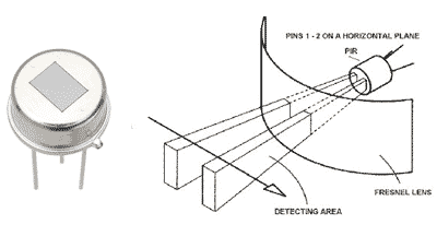
Below I show you the pinout diagram of a PIR sensor.

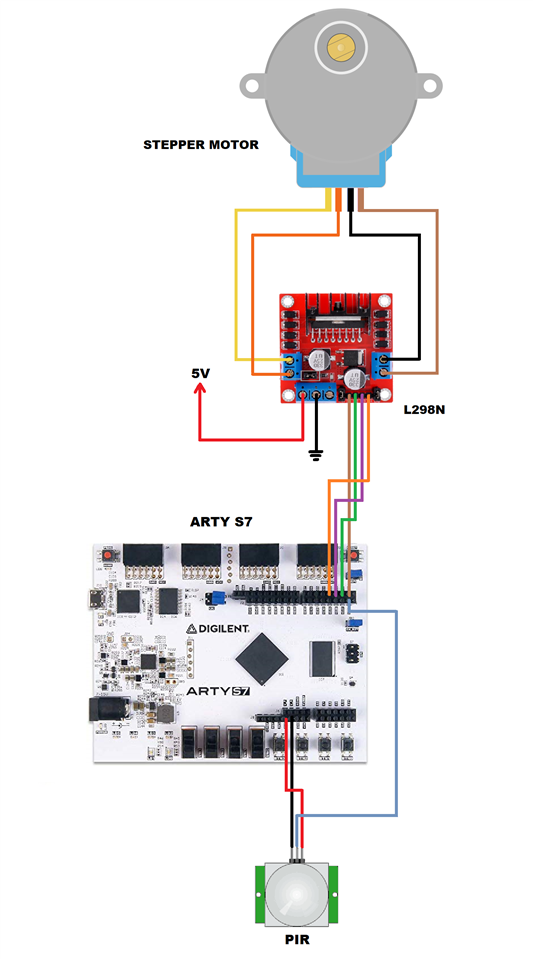
Adding the PIR Motion Sensor
Below I show you the electrical diagram with the PIR sensor connected to our Mini Elevator.
Experimenting with the PIR Motion Sensor
What function does the PIR motion sensor perform?
- I am using the PIR motion sensor to replace the enable switch (sw1) used in chapter 4 of this tutorial.
- When no infrared light motion is detected, the sensor output is 0 volts.
- When it detects infrared light motion, the sensor output is 3.3 volts. I mean a logical one.
- In the PIR motion sensor I have calibrated the time adjustment potentiometer between measurements to 14 seconds.
- The time of 14 seconds was obtained experimentally, and is the approximate time it takes for the mini-elevator cabin to travel from floor one to floor two.
- Now the user of the mini elevator operates the device as follows: a) activate switch sw0 to go up, and deactivate switch swo to go down; and b) passes the hand through the PIR sensor to start the movement of the mini-elevator cabin, and it automatically stops when it has reached its destination (14 seconds approx).
Modifications to the Project Code
After the change explained above, the finished main.sv file looks like this:
`timescale 1ns / 1ps
//////////////////////////////////////////////////////////////////////////////////
// AUTHOR:GUILLERMO PEREZ GUILLEN
//////////////////////////////////////////////////////////////////////////////////

module main (
    input wire logic clk,
    input wire logic sw,
    input wire logic en,
    input wire logic io26,
    output     logic [3:0] led,
    output     logic io0,
    output     logic io1,
    output     logic io2,
    output     logic io3
    );

    // stepper motor phases
    localparam DELAY = 1;

    logic [3:0] cnt_phase;  // 4-bit allows up to 15 second phase
    logic light_set;  // active elevator: 0 = move down, 1 = move up

    // generate 20 milliseconds strobe
    localparam DIV_BY = 27'd500_000;  // 500000 -> 0.020 sec
    logic stb;
    logic [$clog2(DIV_BY)-1:0] cnt_stb;
    always_ff @(posedge clk) begin
        if (cnt_stb != DIV_BY-1) begin
            stb <= 0;
            cnt_stb <= cnt_stb + 1;
        end else begin
            stb <= 1;
            cnt_stb <= 0;
        end
    end

    // finite state machine: state change & behavior
    enum {IDLE, INIT, FIRST_STEP, SECOND_STEP, THIRD_STEP, FOURTH_STEP, STOP} state;
    always_ff @(posedge clk) begin
        light_set = sw;
        case (state)
            IDLE: state <= INIT;
            INIT: begin
                state <= FIRST_STEP;
                light_set <= ~light_set;  // switch active light set
            end
            FIRST_STEP: begin
                if (cnt_phase == 0) begin
                    state <= SECOND_STEP;
                    cnt_phase <= DELAY;
                end else if (stb) cnt_phase <= cnt_phase - 1;
            end
            SECOND_STEP: begin
                if (cnt_phase == 0) begin
                    state <= THIRD_STEP;
                    cnt_phase <= DELAY;
                end else if (stb) cnt_phase <= cnt_phase - 1;
            end
            THIRD_STEP: begin
                if (cnt_phase == 0) begin
                    state <= FOURTH_STEP;
                    cnt_phase <= DELAY;
                end else if (stb) cnt_phase <= cnt_phase - 1;
            end
            FOURTH_STEP: begin
                if (cnt_phase == 0) begin
                    state <= STOP;
                    cnt_phase <= DELAY;
                    light_set <= ~light_set;  // switch active light set
                end else if (stb) cnt_phase <= cnt_phase - 1;
            end
            STOP: begin
//                if (en == 1'b1)
                if (io26 == 1'b1)
                    state <= FIRST_STEP;
                else
                    state <= STOP;
            end
            default: state <= STOP;
        endcase
    end

    // set LEDS based on active light set and state
    always_ff @(posedge clk) begin
        case (state)
            FIRST_STEP: begin
                if (light_set == 0) begin
                    led[0] = 1;
                    led[1] = 0;
                    led[2] = 0;
                    led[3] = 1;
                    io0 = 1;
                    io1 = 0;
                    io2 = 0;
                    io3 = 1;
                end else if (light_set == 1) begin
                    led[0] = 0;
                    led[1] = 1;
                    led[2] = 0;
                    led[3] = 1;
                    io0 = 0;
                    io1 = 1;
                    io2 = 0;
                    io3 = 1;
                end
            end

            SECOND_STEP: begin
                if (light_set == 0) begin
                    led[0] = 1;
                    led[1] = 0;
                    led[2] = 1;
                    led[3] = 0;
                    io0 = 1;
                    io1 = 0;
                    io2 = 1;
                    io3 = 0;
                end else if (light_set == 1) begin
                    led[0] = 0;
                    led[1] = 1;
                    led[2] = 1;
                    led[3] = 0;
                    io0 = 0;
                    io1 = 1;
                    io2 = 1;
                    io3 = 0;
                end
            end

            THIRD_STEP: begin
                if (light_set == 0) begin
                    led[0] = 0;
                    led[1] = 1;
                    led[2] = 1;
                    led[3] = 0;
                    io0 = 0;
                    io1 = 1;
                    io2 = 1;
                    io3 = 0;
                end else if (light_set == 1) begin
                    led[0] = 1;
                    led[1] = 0;
                    led[2] = 1;
                    led[3] = 0;
                    io0 = 1;
                    io1 = 0;
                    io2 = 1;
                    io3 = 0;
                end
            end
            FOURTH_STEP: begin
                if (light_set == 0) begin
                    led[0] = 0;
                    led[1] = 1;
                    led[2] = 0;
                    led[3] = 1;
                    io0 = 0;
                    io1 = 1;
                    io2 = 0;
                    io3 = 1;
                end else if (light_set == 1) begin
                    led[0] = 1;
                    led[1] = 0;
                    led[2] = 0;
                    led[3] = 1;
                    io0 = 1;
                    io1 = 0;
                    io2 = 0;
                    io3 = 1;
                end
            end

            STOP: begin
                if (light_set == 0) begin
                    led[0] = 0;
                    led[1] = 0;
                    led[2] = 0;
                    led[3] = 0;
                    io0 = 0;
                    io1 = 0;
                    io2 = 0;
                    io3 = 0;
                end else if (light_set == 1) begin
                    led[0] = 0;
                    led[1] = 0;
                    led[2] = 0;
                    led[3] = 0;
                    io0 = 0;
                    io1 = 0;
                    io2 = 0;
                    io3 = 0;
                end
            end
        endcase
    end
endmodule
And the Arty-S7-50-Master.xdc file looks like this:
## Configuration options, can be used for all designs
set_property BITSTREAM.CONFIG.CONFIGRATE 50 [current_design]
set_property CONFIG_VOLTAGE 3.3 [current_design]
set_property CFGBVS VCCO [current_design]
set_property BITSTREAM.CONFIG.SPI_BUSWIDTH 4 [current_design]
set_property CONFIG_MODE SPIx4 [current_design]

## SW3 is assigned to a pin M5 in the 1.35v bank. This pin can also be used as
## the VREF for BANK 34. To ensure that SW3 does not define the reference voltage
## and to be able to use this pin as an ordinary I/O the following property must
## be set to enable an internal VREF for BANK 34. Since a 1.35v supply is being
## used the internal reference is set to half that value (i.e. 0.675v). Note that
## this property must be set even if SW3 is not used in the design.
set_property INTERNAL_VREF 0.675 [get_iobanks 34]

## Clock Signals
set_property -dict { PACKAGE_PIN R2    IOSTANDARD SSTL135 } [get_ports { clk }]; #IO_L12P_T1_MRCC_34 Sch=ddr3_clk[200]
create_clock -add -name sys_clk_pin -period 10.000 -waveform {0 5.000}  [get_ports { clk }];

## LEDs
set_property -dict { PACKAGE_PIN E18   IOSTANDARD LVCMOS33 } [get_ports { led[0] }]; #IO_L16N_T2_A27_15 Sch=led[2]
set_property -dict { PACKAGE_PIN F13   IOSTANDARD LVCMOS33 } [get_ports { led[1] }]; #IO_L17P_T2_A26_15 Sch=led[3]
set_property -dict { PACKAGE_PIN E13   IOSTANDARD LVCMOS33 } [get_ports { led[2] }]; #IO_L17N_T2_A25_15 Sch=led[4]
set_property -dict { PACKAGE_PIN H15   IOSTANDARD LVCMOS33 } [get_ports { led[3] }]; #IO_L18P_T2_A24_15 Sch=led[5]

## ChipKit Outer Digital Header
set_property -dict { PACKAGE_PIN L13   IOSTANDARD LVCMOS33 } [get_ports { io0 }]; #IO_0_14 Sch=ck_io[0]
set_property -dict { PACKAGE_PIN N13   IOSTANDARD LVCMOS33 } [get_ports { io1 }]; #IO_L6N_T0_D08_VREF_14   Sch=ck_io[1]
set_property -dict { PACKAGE_PIN L16   IOSTANDARD LVCMOS33 } [get_ports { io2 }]; #IO_L3N_T0_DQS_EMCCLK_14 Sch=ck_io[2]
set_property -dict { PACKAGE_PIN R14   IOSTANDARD LVCMOS33 } [get_ports { io3 }]; #IO_L13P_T2_MRCC_14      Sch=ck_io[3]

## ChipKit Inner Digital Header
## Note: these pins are shared with PMOD Headers JC and JD and cannot be used at the same time as the applicable PMOD interface(s)
set_property -dict { PACKAGE_PIN U11   IOSTANDARD LVCMOS33 } [get_ports { io26 }]; #IO_L24P_T3_A01_D17_14        Sch=jd10/ck_io[26]

## Switches
set_property -dict { PACKAGE_PIN H14   IOSTANDARD LVCMOS33 } [get_ports { sw }]; #IO_L20N_T3_A19_15 Sch=sw[0]
set_property -dict { PACKAGE_PIN H18   IOSTANDARD LVCMOS33 } [get_ports { en }]; #IO_L21P_T3_DQS_15 Sch=sw[1]
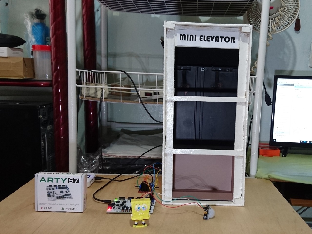
Test
I am amazed that I was able to do this project without so much wiring. Below I show you a test done with the PIR motion sensor added to the Mini Elevator.
This tutorial is nearing its end. In the next chapter I have planned an experiment with this Arty S7 board.