


Introduction
Now a little project: a servo interface. This will give me a chance to experiment with some very simple communication between the microcontroller and the FPGA on my VIDOR 4000 board.
I'm going to have 8 servo channels, which the FPGA will drive out on the D0 to D7 pins of the header, and the control will be via a simple, write-only SPI interface on the SCK and MOSI pins from the SAM processor [with A0 used as the SS chip select].
I'm sure, if I looked around, I could find an existing design, but I thought it would make for a more interesting blog if I did one for myself, from the ground up.
The Design
I don't know much at all about model servos, so I had to look at a few datasheets, the Wikipedia page [1], and a couple of websites to find out what the waveform I'm going to generate should be like.
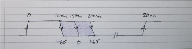
It's a repetitive waveform, where the timing of the falling edge after the positive edge determines the servo angle. Like this:
Traditionally, the repetition rate was 50Hz (20ms period). I'll stick to that for this blog, though it wouldn't be too difficult to change it or even make it programmable.
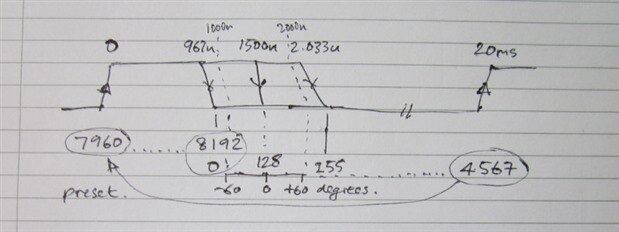
Here's the waveform again as I drew it, annotated with the various counter values in a way that's probably totally confusing, but might begin to make some sense if you read the explanation below.
The neutral position (for the hobby servos I'm using, that will be the centre position, which I'll call 0 degrees) occurs when the falling edge is 1500us after the rising edge.
I had to make a decision as to the resolution I was going to work to. Since the total travel is 120 degrees, working with 8-bit data looked reasonable as a start. That gives half a degree per bit, which I believe is about the size of the deadband with cheap servos. Being a flexible design in an FPGA, I could always increase the resolution later if I didn't like the result.
Since -60 degrees is at 1000us and +60 degrees is at 2000u, we can quickly work out that this is 8.3333us per degree. For half degree resolution, I need half that, ie 4.1666us. I can obtain that by dividing the 48MHz FPGA clock by 200, so I'm going to have an 8-bit prescaler to generate an enable signal every 200 clocks for the servo stuff to run on.
So how about the other end? The processor interface.
I've already mentioned that it's going to be SPI. That's because it's very simple to implement (it's even simpler with a cut-down, receive-only design like this), and there's also support for it on the SAM side of things, so it's very easy to use in the processor sketch. SPI data is bit-serial, so to receive it we'll need a shift register. In hardware terms, this is little more than a serial-data-in, parallel-data-out shift register.
I have a choice as to how fast I make the SPI clock when I set it up with the Arduino library. Quite arbitrarily, I'm going to set it to 1MHz. [The default on the VIDOR board seems to be 4MHz, as I discovered when I misunderstood that the SPI.beginTransaction function has to come after the SPI.begin, and not before.] That's quite fast enough for what I want to do here, but is slow enough that I won't have any problems at all with dealing with it on the FPGA. Although you might think I'd use something labelled 'clock' as a clock input to the FPGA, I'm not going to. Instead I'm going to treat it as data that I'll sample to find the positive-going edge that marks the time to pick up the data.
SPI is sent as a byte or multiples of a byte. I'm going to choose 2-bytes for each transaction, so my shift register will need to be 16 bits. The first byte will be the address for a channel, the next the data.
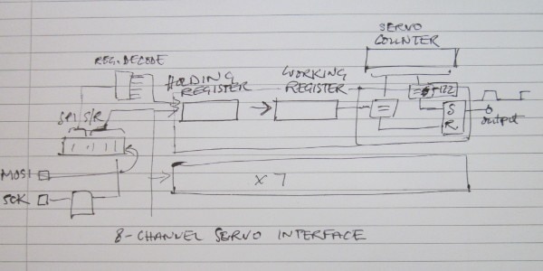
After the SPI interface, I need some holding registers to store the data for each channel. As well as the holding registers, I'm also going to have a working register for each channel. The transfer will occur at the start of the cycle, well out of the way of the comparisons that determine the falling edges.
Those stored values then get compared to a counter for generating the output waveforms. Although I could design the output stage and duplicate it eight times, with a counter for each channel, a little thought shows that the counter does exactly the same thing in each case and can be shared between all eight.
Putting all of that together then gives me something like this as a block diagram:
The VHDL
Here's the VHDL I ended up with. It's reasonably well commented, so you should be able to follow it and what it's doing. If anything doesn't make sense, ask in the comments.
---------------------------------------------------------------
--- Filename: servo.vhd                                     ---
--- Target device: 16CL016YU256C8G                          ---
---                                                         ---
--- 8-Channel Servo driver with output at 100Hz             ---
---                                                         ---
--- Interfaces to microcontroller with SPI [write only]     ---
--- 16-bit data, msb first, and mode (0,0) for the clock    ---
---                                                         ---
--- msb                                     lsb             ---
--- x x x x x A2 A1 A0  D7 D6 D5 D4 D3 D2 D1 D0             ---
---                                                         ---
--- where A is the channel address                          ---
--- D is two's complement setting in half degree increments ---
---                                                         ---
--- Jon Clift 18th July 2021                                ---
---                                                         ---
---------------------------------------------------------------
--- Rev    Date         Comments                            ---
--- 1.0    18-Jul-21                                        ---
---------------------------------------------------------------


library IEEE;
use IEEE.std_logic_1164.all;
---use IEEE.numeric_std.all;
use ieee.std_logic_arith.all;
use ieee.std_logic_unsigned.all;


entity servo_top is port(


   --- system signals
   CLKi:             in std_logic;
   RESn:             in std_logic;

   --- MKR PINS
   MKR_D:            out std_logic_vector(7 downto 0);
MOSI:             in std_logic;
SCK:              in std_logic;
SS:               in std_logic;

   --- SDRAM
   SDRAM_CK:         out std_logic;
   SDRAM_CSn:        out std_logic;
   SDRAM_CKE:        out std_logic;

   --- NINA module
   WM10_RESn:        out std_logic

   );


end servo_top;


architecture arch_servo_top of servo_top is


signal prescaler: std_logic_vector(7 downto 0);
signal servo_en, servo_transfer_en: std_logic;
signal servo_counter: std_logic_vector(12 downto 0);
signal spi_clk_del1, spi_clk_del2, spi_en: std_logic;
signal spi_ss_del1, spi_ss_del2, spi_ss_end: std_logic;
signal spi_data_del1, spi_data_del2: std_logic;
signal spi_shift_register: std_logic_vector(15 downto 0);
signal servo_hold_0: std_logic_vector(7 downto 0);
signal servo_hold_1: std_logic_vector(7 downto 0);
signal servo_hold_2: std_logic_vector(7 downto 0);
signal servo_hold_3: std_logic_vector(7 downto 0);
signal servo_hold_4: std_logic_vector(7 downto 0);
signal servo_hold_5: std_logic_vector(7 downto 0);
signal servo_hold_6: std_logic_vector(7 downto 0);
signal servo_hold_7: std_logic_vector(7 downto 0);
signal servo_data_0: std_logic_vector(7 downto 0);
signal servo_data_1: std_logic_vector(7 downto 0);
signal servo_data_2: std_logic_vector(7 downto 0);
signal servo_data_3: std_logic_vector(7 downto 0);
signal servo_data_4: std_logic_vector(7 downto 0);
signal servo_data_5: std_logic_vector(7 downto 0);
signal servo_data_6: std_logic_vector(7 downto 0);
signal servo_data_7: std_logic_vector(7 downto 0);
signal servo_out: std_logic_vector(7 downto 0);


begin


   --- everything that runs from the 48MHz clock input on CLKi


    clocked_stuff: process (CLKi)
        begin
            if (CLKi'event and CLKi = '1') then

                --- prescaler down to 4.16666us period (divide by 200)

                if (prescaler(7 downto 0) = "00000000") then --- if reached 0
                    prescaler(7 downto 0) <= "11000111"; ---   preset to 199
                    servo_en <= '1'; ---   and set enable for one cycle
                else --- else count down
                    prescaler <= prescaler - 1;
                    servo_en <= '0'; ---   keeping enable low rest of time
                end if;


--- the servo counter counts every 4.16666us (equivalent to half a degree on the servo)
--- period is 4800 counts: 4.16666us x 4800 = 20ms (100Hz)

                if (servo_en = '1') then
  if (servo_counter(12 downto 0) = "1000111010111") then --- if reached 4567
servo_counter(12 downto 0) <= "1111100011000"; --- preset (skip ahead) to 7960 (-232)
servo_out(7 downto 0) <= "11111111"; --- and set all the servo outputs high
                     servo_transfer_en <= '1'; ---
else --- else
servo_counter <= servo_counter + 1; --- count down
                     servo_transfer_en <= '0'; ---
end if;
end if;


--- the SPI interface

spi_clk_del1 <= SCK;
spi_clk_del2 <= spi_clk_del1;

spi_ss_del1 <= SS;
spi_ss_del2 <= spi_ss_del1;

spi_data_del1 <= MOSI;
spi_data_del2 <= spi_data_del1;


if((spi_clk_del1 = '1') and (spi_clk_del2 = '0')) then
spi_en <= '1';
else
spi_en <= '0';
end if;


if((spi_ss_del1 = '1') and (spi_ss_del2 = '0')) then
spi_ss_end <= '1';
else
spi_ss_end <= '0';
end if;


if((spi_en = '1') and (spi_ss_del2 = '0')) then

spi_shift_register(15 downto 1) <= spi_shift_register(14 downto 0);
spi_shift_register(0) <= spi_data_del2;

end if;


--- at end of ss (SPI 'chip select' going high at end of transfer)
--- transfer data from spi shift register to the addressed
--- servo data holding register
--- bit 7 is negated to convert 2's complement back to binary

if(spi_ss_end = '1') then

case (spi_shift_register(10 downto 8)) is
when "000" =>
servo_hold_0(6 downto 0) <= spi_shift_register(6 downto 0);
servo_hold_0(7) <= not spi_shift_register(7);
when "001" =>
servo_hold_1(6 downto 0) <= spi_shift_register(6 downto 0);
servo_hold_1(7) <= not spi_shift_register(7);
when "010" =>
servo_hold_2(6 downto 0) <= spi_shift_register(6 downto 0);
servo_hold_2(7) <= not spi_shift_register(7);
when "011" =>
servo_hold_3(6 downto 0) <= spi_shift_register(6 downto 0);
servo_hold_3(7) <= not spi_shift_register(7);
when "100" =>
servo_hold_4(6 downto 0) <= spi_shift_register(6 downto 0);
servo_hold_4(7) <= not spi_shift_register(7);
when "101" =>
servo_hold_5(6 downto 0) <= spi_shift_register(6 downto 0);
servo_hold_5(7) <= not spi_shift_register(7);
when "110" =>
servo_hold_6(6 downto 0) <= spi_shift_register(6 downto 0);
servo_hold_6(7) <= not spi_shift_register(7);
when "111" =>
servo_hold_7(6 downto 0) <= spi_shift_register(6 downto 0);
servo_hold_7(7) <= not spi_shift_register(7);
when others =>
end case;

end if;


--- update the data registers from the holding registers
--- do this at start of period, well before they get used

if(servo_transfer_en = '1') then

servo_data_0 <= servo_hold_0;
servo_data_1 <= servo_hold_1;
servo_data_2 <= servo_hold_2;
servo_data_3 <= servo_hold_3;
servo_data_4 <= servo_hold_4;
servo_data_5 <= servo_hold_5;
servo_data_6 <= servo_hold_6;
servo_data_7 <= servo_hold_7;
end if;

  --- set each servo output low at the appropriate time
--- (they were all set high at the same instant: see servo counter above)

                if ((servo_en = '1') and (servo_counter(10 downto 8) = "000")) then

if (servo_counter(7 downto 0) = servo_data_0(7 downto 0)) then --- if same
servo_out(0) <= '0'; --- set output low
end if;


if (servo_counter(7 downto 0) = servo_data_1(7 downto 0)) then
servo_out(1) <= '0';
end if;


if (servo_counter(7 downto 0) = servo_data_2(7 downto 0)) then
servo_out(2) <= '0';
end if;


if (servo_counter(7 downto 0) = servo_data_3(7 downto 0)) then
servo_out(3) <= '0';
end if;


if (servo_counter(7 downto 0) = servo_data_4(7 downto 0)) then
servo_out(4) <= '0';
end if;


if (servo_counter(7 downto 0) = servo_data_5(7 downto 0)) then
servo_out(5) <= '0';
end if;


if (servo_counter(7 downto 0) = servo_data_6(7 downto 0)) then
servo_out(6) <= '0';
end if;


if (servo_counter(7 downto 0) = servo_data_7(7 downto 0)) then
servo_out(7) <= '0';
end if;


end if;

end if;

end process clocked_stuff;


--- connect servo outs to the MKR pins

MKR_D <= servo_out;

--- hold some of the unused, board hardware components in inactive state

SDRAM_CK <= CLKI;
SDRAM_CSn <= '1';
SDRAM_CKE <= '1';

WM10_RESn <= '0';


end arch_servo_top;
(Sorry about the strange formatting. The original was fine. If I have the energy tomorrow, I'll try editing it.)
I haven't put a licence on this (I'm still unsure what the best way to licence something like this is). Effectively, you can do what you like with it, but there's no warranty, no claim of fitness for purpose, nor any obligation on me to support it in any way whatsoever.
The Sketch
For the sketch, I modified the template provided here [thank you, C Helmich]:
https://github.com/chelmich/vidor_template/tree/master/arduino/vidor_template
just adding in the SPI stuff for testing the interface from the processor to the FPGA.
Here's how the sketch part looked after I'd finished:
#include <wiring_private.h>
#include <SPI.h>
#include "jtag.h"
#include "defines.h"


__attribute__ ((used, section(".fpga_bitstream_signature")))
const unsigned char signatures[4096] = {
    #include "signature.h"
};


__attribute__ ((used, section(".fpga_bitstream")))
const unsigned char bitstream[] = {
    #include "app.h"
};


void FPGA_init (){
    // enable fpga clock
    pinPeripheral(30, PIO_AC_CLK);
    clockout(0, 1);


    // wait for clock to come up (unnecessary?)
    delay(1000);


    // send bitstream over jtag
    uint32_t ptr[1] = {3};
    jtagInit();
    mbPinSet();
    mbEveSend(ptr, 1);
    jtagDeinit();
}


void setup (){
    FPGA_init();


    delay(1000);


    // turn on built in LED
    pinMode(LED_BUILTIN, OUTPUT);


    // set A0 as output - this is SS (device select) for SPI
    pinMode(A0, OUTPUT);
    // start SPI
    SPI.begin();
}


void loop (){


unsigned char servoChannel;
signed char servoData[] = {-128,-120,-60,0,60,90,120,127};


SPI.beginTransaction(SPISettings(1000000,MSBFIRST,SPI_MODE0));


while(1){
  for(servoChannel=0;servoChannel<8;servoChannel++) {
    digitalWrite(A0, LOW);                  // SS low
//    delayMicroseconds(2);
    SPI.transfer(servoChannel);             // send channel
    SPI.transfer(servoData[servoChannel]);  // send channel data
//    delayMicroseconds(2);
    digitalWrite(A0, HIGH);                 // SS high
//    servoData[servoChannel] = (signed char) random(256);  // pick new random value for next time through
    servoData[servoChannel]++;  //
    delayMicroseconds(10);
    }
  delay(100);
  }

SPI.end();
}
My app.h came from my own VHDL design, and the jtag.c and jtag.h files were the same as the template. [There's no mention of a licence, so I presume it's a generous 'do what you like with this' piece of code.]
The Servo Interface Working
Here are some oscilloscope traces from the working design. This is with the initialisation values from my code.
signed char servoData[] = {-128,-120,-60,0,60,90,120,127};
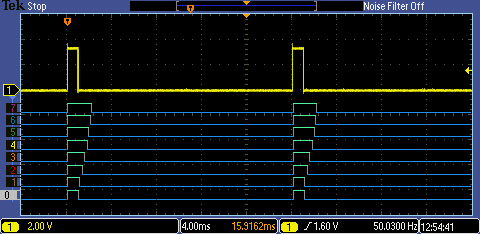
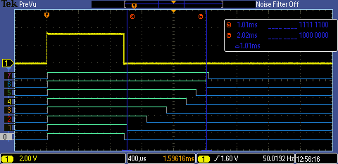
This first one shows the complete cycle. The logic-analyser section shows the MKR D0 to D7 outputs from the VIDOR headers. The one marked '0' is D0, and so on. The yellow, analogue trace is a duplicate of D0.
We can see the various pulse widths as they should be. This also shows that I've got the output frequency correct at 50Hz (give or take a little variation because of the jitter on the FPGA's clock).
Here it is again, in a bit more detail on a faster timebase:
The cursors I've placed at the 1000us and 2000us positions, which line up with values of -120 and +120 sent from the microcontroller [effectively, -60 and +60 degrees, the limits of my servos].
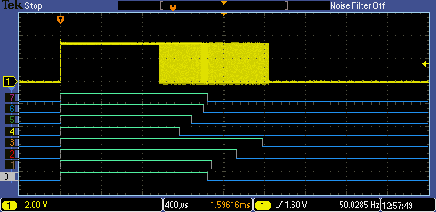
With this next one, I have the data for each of the channels incrementing 10 times a second. With the phosphor set to infinity, the analogue trace then shows all the possible positions for the falling edge [the analyser section doesn't persist in the same way as the analogue trace, so you only see the most recent trace there].
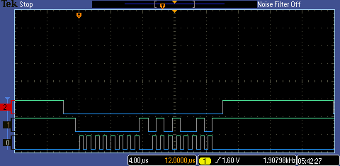
Finally, here's a quick look at the SPI. Trace '0' is the clock, '1' is the data, and '2' is the SS signal.
Conclusions
That didn't go too badly, and I've got the beginnings of a working design. It uses about 1.5% of the logic blocks of the FPGA, so there's plenty left for extending or elaborating the design, or for other uses entirely.
Later, I'll try wiring up some servos [if I can find them: I think I might have three, somewhere or other] and then I'll see if it works for real.
References
[1] https://en.wikipedia.org/wiki/Servo_(radio_control) [2] VIDOR 4000: Johnson Counter
If you found this interesting and would like to see other blogs I've written, a list can be found here: jc2048 Blog Index |

Top Comments
-

michaelkellett
-
Cancel
-
Vote Up
+4
Vote Down
-
-
Sign in to reply
-
More
-
Cancel
-

jc2048
in reply to michaelkellett
-
Cancel
-
Vote Up
+1
Vote Down
-
-
Sign in to reply
-
More
-
Cancel
Comment-

jc2048
in reply to michaelkellett
-
Cancel
-
Vote Up
+1
Vote Down
-
-
Sign in to reply
-
More
-
Cancel
Children