element14 Community
element14 Community
    Register Log In
  • Site
  • Search
  • Log In Register
  • About Us
  • Community Hub
    Community Hub
    • What's New on element14
    • Feedback and Support
    • Benefits of Membership
    • Personal Blogs
    • Members Area
    • Achievement Levels
  • Learn
    Learn
    • Ask an Expert
    • eBooks
    • element14 presents
    • Learning Center
    • Tech Spotlight
    • STEM Academy
    • Webinars, Training and Events
    • Learning Groups
  • Technologies
    Technologies
    • 3D Printing
    • FPGA
    • Industrial Automation
    • Internet of Things
    • Power & Energy
    • Sensors
    • Technology Groups
  • Challenges & Projects
    Challenges & Projects
    • Design Challenges
    • element14 presents Projects
    • Project14
    • Arduino Projects
    • Raspberry Pi Projects
    • Project Groups
  • Products
    Products
    • Arduino
    • Avnet Boards Community
    • Dev Tools
    • Manufacturers
    • Multicomp Pro
    • Product Groups
    • Raspberry Pi
    • RoadTests & Reviews
  • Store
    Store
    • Visit Your Store
    • Choose another store...
      • Europe
      •  Austria (German)
      •  Belgium (Dutch, French)
      •  Bulgaria (Bulgarian)
      •  Czech Republic (Czech)
      •  Denmark (Danish)
      •  Estonia (Estonian)
      •  Finland (Finnish)
      •  France (French)
      •  Germany (German)
      •  Hungary (Hungarian)
      •  Ireland
      •  Israel
      •  Italy (Italian)
      •  Latvia (Latvian)
      •  
      •  Lithuania (Lithuanian)
      •  Netherlands (Dutch)
      •  Norway (Norwegian)
      •  Poland (Polish)
      •  Portugal (Portuguese)
      •  Romania (Romanian)
      •  Russia (Russian)
      •  Slovakia (Slovak)
      •  Slovenia (Slovenian)
      •  Spain (Spanish)
      •  Sweden (Swedish)
      •  Switzerland(German, French)
      •  Turkey (Turkish)
      •  United Kingdom
      • Asia Pacific
      •  Australia
      •  China
      •  Hong Kong
      •  India
      •  Korea (Korean)
      •  Malaysia
      •  New Zealand
      •  Philippines
      •  Singapore
      •  Taiwan
      •  Thailand (Thai)
      • Americas
      •  Brazil (Portuguese)
      •  Canada
      •  Mexico (Spanish)
      •  United States
      Can't find the country/region you're looking for? Visit our export site or find a local distributor.
  • Translate
  • Profile
  • Settings
Sensors
  • Technologies
  • More
Sensors
Blog ROHM Magnetometer Sensor BM1422AGMV
  • Blog
  • Forum
  • Documents
  • Quiz
  • Events
  • Polls
  • Members
  • Mentions
  • Sub-Groups
  • Tags
  • More
  • Cancel
  • New
Join Sensors to participate - click to join for free!
  • Share
  • More
  • Cancel
Group Actions
  • Group RSS
  • More
  • Cancel
Engagement
  • Author Author: Jan Cumps
  • Date Created: 23 Nov 2018 2:34 PM Date Created
  • Views 6961 views
  • Likes 8 likes
  • Comments 27 comments
  • RoadTest
  • rohm
  • road_test
Related
Recommended

ROHM Magnetometer Sensor BM1422AGMV

Jan Cumps
Jan Cumps
23 Nov 2018

I'm Road Testing the Rohm SensorShield-EVK-003 (Arduino Compatible) and the sensors that come with it.

In this post, the Geo Magnetic Sensor BM1422AGMVBM1422AGMV.

image


The Sensor Shield ecosystemSensor Shield ecosystem is ROHM's test bed for their sensors. It's an Arduino form shield with a number of slots.

The small evaluation boards for their sensors plug into that board.

For each of the sensors, there's an example sketch available.

For this blog post, I'm testing the Magnetometer sensor that comes with the kit.


Evaluation Board


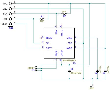
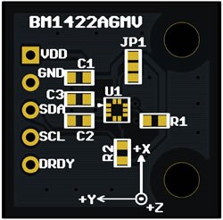
This tiny PCB contains the sensor, required bypass capacitors, optional footprints for i2c pull-ups and a jumper to change the address of the sensor.

imageimage


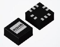
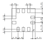
The sensor comes in a QFN  package.

imageimage


The datasheet does not explain the physical constructions.

But it's safe to assume that there are 3 sensors on board. Each physically mounted in one of the 3 axis.


The quote below - from (deprecated) android documentation - shows how the axis are interpreted in a smartphone.

  • Azimuth (degrees of rotation about the -z axis). This is the angle between the device's current compass direction and magnetic north. If the top edge of the device faces magnetic north, the azimuth is 0 degrees; if the top edge faces south, the azimuth is 180 degrees. Similarly, if the top edge faces east, the azimuth is 90 degrees, and if the top edge faces west, the azimuth is 270 degrees.
  • Pitch (degrees of rotation about the x axis). This is the angle between a plane parallel to the device's screen and a plane parallel to the ground. If you hold the device parallel to the ground with the bottom edge closest to you and tilt the top edge of the device toward the ground, the pitch angle becomes positive. Tilting in the opposite direction— moving the top edge of the device away from the ground—causes the pitch angle to become negative. The range of values is -180 degrees to 180 degrees.
  • Roll (degrees of rotation about the y axis). This is the angle between a plane perpendicular to the device's screen and a plane perpendicular to the ground. If you hold the device parallel to the ground with the bottom edge closest to you and tilt the left edge of the device toward the ground, the roll angle becomes positive. Tilting in the opposite direction—moving the right edge of the device toward the ground— causes the roll angle to become negative. The range of values is -90 degrees to 90 degrees.

source: developer.android.com


Firmware


What surprised me is that the example available from the ROHM website is better than what's on github.

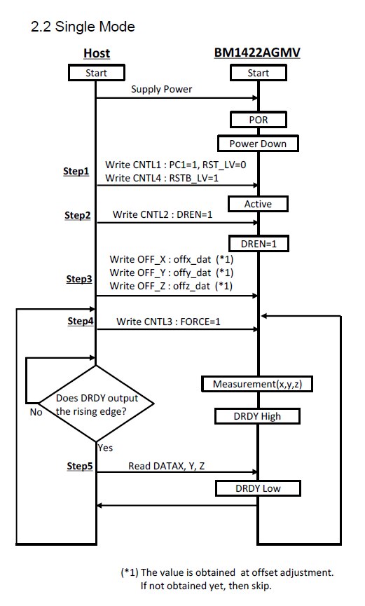
The downloadable one supports a trigger when data is available from the magnetometer.

That's a useful demo for this device and it is interesting for Arduino education.

The Software registers the trigger, and based on the mode of the device attaches that trigger on the falling or rising edge.

image

image source: BM1422AGMV datasheet


I'm quoting from both sketch and library.

Copyright (c) 2017 ROHM Co.,Ltd.

Please check the - very liberal - copyright notice in the source files.


Here's the trigger handler. It's defined in the sketch.

void bm1422agmv_isr(void)
{
  bm1422agmv.set_drdy_flg();
}


The trigger is attached in the Setup() method in the sketch.

BM1422AGMV bm1422agmv(BM1422AGMV_DEVICE_ADDRESS_0E);
// ...
void setup() {
// ...
  Wire.begin();
  rc = bm1422agmv.init();
// ...

  bm1422agmv.isr_func(0, bm1422agmv_isr);
}


We see the constructor and three methods used from the ROHM library BM1422AGMV.

You can check out the C++ code in the zip file you downloaded from ROHM website.

I'll show some extracts from them, with focus on the steps happening:


Constructor

#define BM1422AGMV_DEVICE_ADDRESS_0E   (0x0E)    // 7bit Addrss

BM1422AGMV::BM1422AGMV(int slave_address)
{
  _device_address = slave_address ;
}


init()

byte BM1422AGMV::init(void)
{
// ...

  _drdy_flg = 0;

  rc = read(BM1422AGMV_WIA, &reg, sizeof(reg));
// ...

  if (reg != BM1422AGMV_WIA_VAL) {
// ...
  }

  // Step1
  reg = BM1422AGMV_CNTL1_VAL;
  rc = write(BM1422AGMV_CNTL1, &reg, sizeof(reg));
// ...

  // Check 12bit or 14bit
  buf[0] = (BM1422AGMV_CNTL1_VAL & BM1422AGMV_CNTL1_OUT_BIT);
  if (buf[0] == BM1422AGMV_CNTL1_OUT_BIT) {
    _sens = BM1422AGMV_14BIT_SENS;
  } else {
    _sens = BM1422AGMV_12BIT_SENS;
  }
  delay(1);
// ...

  buf[0] = (BM1422AGMV_CNTL4_VAL >> 8) & 0xFF;
  buf[1] = (BM1422AGMV_CNTL4_VAL & 0xFF);
  rc = write(BM1422AGMV_CNTL4, buf, sizeof(buf));
// ...
  // Step2
  reg = BM1422AGMV_CNTL2_VAL;
  rc = write(BM1422AGMV_CNTL2, &reg, sizeof(reg));
// ...

  // Step3

  // Option
  reg = BM1422AGMV_AVE_A_VAL;
  rc = write(BM1422AGMV_AVE_A, &reg, sizeof(reg));
// ...

  return (rc);
}


isr_func()

void BM1422AGMV::isr_func(int int_num, void func(void))
{
  if (BM1422AGMV_CNTL2_VAL & BM1422AGMV_CNTL2_DRP) {
    attachInterrupt(int_num, func, RISING);
  } else {
    attachInterrupt(int_num, func, FALLING);
  }
}


In the loop() method, the sketch gets data from the sensor.

void loop() {
  byte rc;
  float mag[3];

  rc = bm1422agmv.get_val(mag);
  if (rc == 0) {
    Serial.print(F("BM1422AGMV XDATA="));
    Serial.print(mag[0], 3);
    Serial.println("[uT]");
    Serial.print(F("BM1422AGMV YDATA="));
    Serial.print(mag[1], 3);
    Serial.println("[uT]");
    Serial.print(F("BM1422AGMV ZDATA="));
    Serial.print(mag[2], 3);
    Serial.println("[uT]");
    Serial.println();
  }
  delay(500);
}


Here are the library functions used:


get_val()

byte BM1422AGMV::get_val(float *data)
{
  byte rc;
  unsigned char val[6];
  signed short mag[3];
  rc = get_rawval(val);
  if (rc != 0) {
    return (rc);
  }
  mag[0] = ((signed short)val[1] << 8) | (val[0]);
  mag[1] = ((signed short)val[3] << 8) | (val[2]);
  mag[2] = ((signed short)val[5] << 8) | (val[4]);
  convert_uT(mag, data);
  return (rc);  
}


get_rawval()

byte BM1422AGMV::get_rawval(unsigned char *data)
{
// ...
  // Step4
  reg = BM1422AGMV_CNTL3_VAL;
  rc = write(BM1422AGMV_CNTL3, &reg, sizeof(reg));

  while(_drdy_flg == 0) {
    delayMicroseconds(100);
  };
  _drdy_flg = 0;

  rc = read(BM1422AGMV_DATAX, data, 6);
// ...
  return (rc);
}


convert_uT

void BM1422AGMV::convert_uT(signed short *rawdata, float *data)
{
  // LSB to uT
  data[0] = (float)rawdata[0] / _sens;
  data[1] = (float)rawdata[1] / _sens;
  data[2] = (float)rawdata[2] / _sens;
}


Here you see how the read from the sensor works in collaboration with the data ready flag and the interrupt.


Measurements


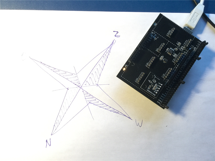
A few measurements, first flat on the table, with the text on the sensor PCB facing:

North:

BM1422AGMV XDATA=1.208[uT]
BM1422AGMV YDATA=-0.375[uT]
BM1422AGMV ZDATA=-76.875[uT]

South:

BM1422AGMV XDATA=-26.333[uT]
BM1422AGMV YDATA=-24.333[uT]
BM1422AGMV ZDATA=-79.417[uT]

East:

BM1422AGMV XDATA=-28.917[uT]
BM1422AGMV YDATA=-4.042[uT]
BM1422AGMV ZDATA=-80.917[uT]

West:

BM1422AGMV XDATA=1.333[uT]
BM1422AGMV YDATA=-26.708[uT]
BM1422AGMV ZDATA=-78.083[uT]


And here pointing the board up and down:

Up West:

BM1422AGMV XDATA=-49.875[uT]
BM1422AGMV YDATA=-41.667[uT]
BM1422AGMV ZDATA=-25.625[uT]

Down West:

BM1422AGMV XDATA=32.375[uT]
BM1422AGMV YDATA=-29.333[uT]
BM1422AGMV ZDATA=-20.542[uT]


i2c Traffic


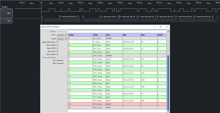
I've captured the traffic of a measurement sequence. Here you can see the effects of the following lines of code:

  rc = read(BM1422AGMV_DATAX, data, 6);

It generates an address write, then 6 blocks of char size data returning.

You may recognise this address on line 3:

#define BM1422AGMV_DATAX              (0x10)

image


I've also measured the impact of moving the sensor in increments of 22°. I'll post them if there's interest.

 

Related blog
ROHM Temperature Sensor BD1020HFV
ROHM Magnetometer Sensor BM1422AGMV
ROHM Hall Sensor BD7411G
ROHM Colour Sensor BH1749NUC
ROHM Colour Sensor BH1749NUC - part 2: Other Firmware Libraries
ROHM Ambient Light and Proximity Sensor RPR-0521RS
  • Sign in to reply

Top Comments

  • Jan Cumps
    Jan Cumps over 6 years ago in reply to genebren +3
    I don't know yet how to write the full review. There's so many diverse things here that reporting on all of them isn't straightforward in a single post. My current idea is to continue writing a post per…
  • kulky64
    kulky64 over 6 years ago +3
    Have you tried to calibrate out hard and soft iron interference? Because from your data it seems there is some present. If you are in Belgium you should be getting total magnetic field of around 49 uT…
  • Jan Cumps
    Jan Cumps over 6 years ago in reply to kulky64 +3
    There is an iron molecule in my neighbourhood
Parents
  • kulky64
    kulky64 over 6 years ago

    Have you tried to calibrate out hard and soft iron interference? Because from your data it seems there is some present. If you are in Belgium you should be getting total magnetic field of around 49 uT with inclination of 66 deg. You can check magnetic field data for your exact GPS location at:

    https://www.ngdc.noaa.gov/geomag-web/#igrfwmm

    From your data I'm getting total length of magnetic field vector ( =sqrt(x^2+y^2+z^2) ) from 48.3 uT to 87.1 uT.

    • Cancel
    • Vote Up +3 Vote Down
    • Sign in to reply
    • More
    • Cancel
  • Jan Cumps
    Jan Cumps over 6 years ago in reply to kulky64

    kulky64  wrote:


    Have you tried to calibrate out hard and soft iron interference? Because from your data it seems there is some present. ...

    Today I’m going to try the sensor without the shield and away from the Arduino. I’ll check if their ground planes are interfering

    • Cancel
    • Vote Up +2 Vote Down
    • Sign in to reply
    • More
    • Cancel
  • Jan Cumps
    Jan Cumps over 6 years ago in reply to Jan Cumps

    Jan Cumps  wrote:

    . ...

    Today I’m going to try the sensor without the shield and away from the Arduino. I’ll check if their ground planes are interfering

    Result, sensor horizontal, PCB print facing South:

    BM1422AGMV XDATA=-11.125[uT]
    BM1422AGMV YDATA=-16.917[uT]
    BM1422AGMV ZDATA=-84.333[uT]
    BM1422AGMV VECTOR=86.730


    image


    With the sensor in exact the same location and direction, with the sensor on top of Arduino and Sensor shield:

    BM1422AGMV XDATA=-28.792[uT]
    BM1422AGMV YDATA=-19.625[uT]
    BM1422AGMV ZDATA=-81.875[uT]
    BM1422AGMV VECTOR=88.981
    • Cancel
    • Vote Up +2 Vote Down
    • Sign in to reply
    • More
    • Cancel
  • jc2048
    jc2048 over 6 years ago in reply to Jan Cumps

    I was going to suggest you might be measuring the supply current field if that wire under the board passes close under the chip, but then realised I was muddling up nT and uT - it doesn't look like it would actually make much difference if the device is as low-powered as it ought to be.

    • Cancel
    • Vote Up +2 Vote Down
    • Sign in to reply
    • More
    • Cancel
Comment
  • jc2048
    jc2048 over 6 years ago in reply to Jan Cumps

    I was going to suggest you might be measuring the supply current field if that wire under the board passes close under the chip, but then realised I was muddling up nT and uT - it doesn't look like it would actually make much difference if the device is as low-powered as it ought to be.

    • Cancel
    • Vote Up +2 Vote Down
    • Sign in to reply
    • More
    • Cancel
Children
No Data
element14 Community

element14 is the first online community specifically for engineers. Connect with your peers and get expert answers to your questions.

  • Members
  • Learn
  • Technologies
  • Challenges & Projects
  • Products
  • Store
  • About Us
  • Feedback & Support
  • FAQs
  • Terms of Use
  • Privacy Policy
  • Legal and Copyright Notices
  • Sitemap
  • Cookies

An Avnet Company © 2025 Premier Farnell Limited. All Rights Reserved.

Premier Farnell Ltd, registered in England and Wales (no 00876412), registered office: Farnell House, Forge Lane, Leeds LS12 2NE.

ICP 备案号 10220084.

Follow element14

  • X
  • Facebook
  • linkedin
  • YouTube