element14 Community
element14 Community
    Register Log In
  • Site
  • Search
  • Log In Register
  • About Us
  • Community Hub
    Community Hub
    • What's New on element14
    • Feedback and Support
    • Benefits of Membership
    • Personal Blogs
    • Members Area
    • Achievement Levels
  • Learn
    Learn
    • Ask an Expert
    • eBooks
    • element14 presents
    • Learning Center
    • Tech Spotlight
    • STEM Academy
    • Webinars, Training and Events
    • Learning Groups
  • Technologies
    Technologies
    • 3D Printing
    • FPGA
    • Industrial Automation
    • Internet of Things
    • Power & Energy
    • Sensors
    • Technology Groups
  • Challenges & Projects
    Challenges & Projects
    • Design Challenges
    • element14 presents Projects
    • Project14
    • Arduino Projects
    • Raspberry Pi Projects
    • Project Groups
  • Products
    Products
    • Arduino
    • Avnet Boards Community
    • Dev Tools
    • Manufacturers
    • Multicomp Pro
    • Product Groups
    • Raspberry Pi
    • RoadTests & Reviews
  • Store
    Store
    • Visit Your Store
    • Choose another store...
      • Europe
      •  Austria (German)
      •  Belgium (Dutch, French)
      •  Bulgaria (Bulgarian)
      •  Czech Republic (Czech)
      •  Denmark (Danish)
      •  Estonia (Estonian)
      •  Finland (Finnish)
      •  France (French)
      •  Germany (German)
      •  Hungary (Hungarian)
      •  Ireland
      •  Israel
      •  Italy (Italian)
      •  Latvia (Latvian)
      •  
      •  Lithuania (Lithuanian)
      •  Netherlands (Dutch)
      •  Norway (Norwegian)
      •  Poland (Polish)
      •  Portugal (Portuguese)
      •  Romania (Romanian)
      •  Russia (Russian)
      •  Slovakia (Slovak)
      •  Slovenia (Slovenian)
      •  Spain (Spanish)
      •  Sweden (Swedish)
      •  Switzerland(German, French)
      •  Turkey (Turkish)
      •  United Kingdom
      • Asia Pacific
      •  Australia
      •  China
      •  Hong Kong
      •  India
      •  Korea (Korean)
      •  Malaysia
      •  New Zealand
      •  Philippines
      •  Singapore
      •  Taiwan
      •  Thailand (Thai)
      • Americas
      •  Brazil (Portuguese)
      •  Canada
      •  Mexico (Spanish)
      •  United States
      Can't find the country/region you're looking for? Visit our export site or find a local distributor.
  • Translate
  • Profile
  • Settings
Test & Tools
  • Technologies
  • More
Test & Tools
Documents Programmable Electronic Load - Analyse the Summing Node Zero Point
  • Blog
  • Forum
  • Documents
  • Files
  • Members
  • Mentions
  • Sub-Groups
  • Tags
  • More
  • Cancel
  • New
Join Test & Tools to participate - click to join for free!
Actions
  • Share
  • More
  • Cancel
Engagement
  • Author Author: Jan Cumps
  • Date Created: 1 Dec 2017 4:08 PM Date Created
  • Last Updated Last Updated: 15 May 2020 3:38 PM
  • Views 8708 views
  • Likes 8 likes
  • Comments 107 comments
Related
Recommended

Programmable Electronic Load - Analyse the Summing Node Zero Point

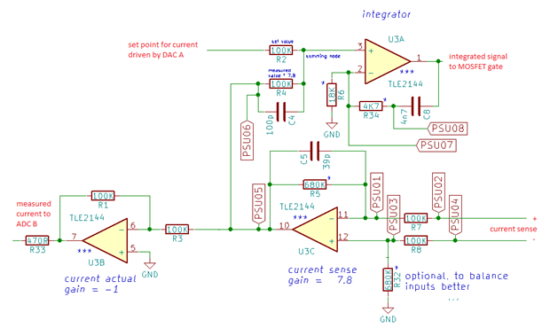
This blog documents investigates the feedback node of the electronic load that Robert Peter Oakes, jc2048 and Jan Cumps are designing.

It's an important spot in the load's design. It measures the set point and the feedback from the output.

When the output is driven to 0, it should be on a potential as close as possible to 0 V.

On the first prototype it's -0.2 V. Not so much off, but the negative value  influences our ADC measurements.

This document checks how we can get this node to 0 V.

image


Because this document is evolving, some comments below may be out of sync with the content. That's because the content is adapted based on the conversation.

The measurements taken here are based on the original design, without R32 in place and U3B + tied to ground.

The current sense side of R7 is connected to ground, and a variable negative voltage from 0 V down is applied to the current sense side of R8 to simulate current being sensed.


The circuit isn't complex. The set point is driven by a DAC. It's set to 0 for this test.

The second input to this node is OpAmp 3C. It has both inputs tied to ground so should theoretically have 0 V at the output.

On my board I measure a potential of -0.212V at the left side of R33.

I hope to get this closer to 0 V to ease the ADC a bit - its performance degrades with negative voltage at its inputs.

Like the other blogs for the electronic load, this is a working document that will be updated with findings from anyone who wants to chime in.


Behaviour at 0V


buzy image

  • metrology
  • differentiator
  • boosterpack
  • opamp
  • msp432
  • launchpad
  • analog
  • laboratory
  • instrument
  • Share
  • History
  • More
  • Cancel
  • Sign in to reply

Top Comments

  • jc2048
    jc2048 over 7 years ago in reply to Robert Peter Oakes +4
    As you say, changing the op-amp is one possibility. There are bipolar op-amps with much lower bias currents, but an alternative nowadays is a precision CMOS op-amp (you'd have to check whether other characteristics…
  • Robert Peter Oakes
    Robert Peter Oakes over 7 years ago +3
    To hopefully simplify things a little We have this, Upper op amp is simply to provide an inversion of the measured value back tot he ADC, hence the gain of -1 Lower right op amp measures the volts across…
  • jc2048
    jc2048 over 7 years ago in reply to Jan Cumps +3
    Love the advertisement for "John's excellent probes". It's like one those things from the old days of American TV where the presenter would suddenly turn, look very earnestly at the camera, and start reading…
Parents
  • Jan Cumps
    Jan Cumps over 7 years ago

    I'm going to redo this exercise now that the OpAmps are replaced with lower bias ones and I have more precise measurement tools.

    From the blog Programmable Electronic Load - LabVIEW Test Automation: Characterise the Instrument we can see that the behaviour is very linear.

    But we have a non-0 start point. When th DAC is driven to 0, there is an output current flowing of a few mA.

    image

    I assume that it's our control circuit that's doing that, because if I disable the output (pull the gate to ground), the current that flows is neglectable. And it's the same FET that's fully blocking the current flow then.


    I've re-stacked the load so that the control board is on top and I have easier access to the measure point.

    I can't use the LCD display in that case. I'll use the SCPI interface to set values.

    image


    I'll measure DAC output and the voltages at relevant control circuit points to see what drives the FET to conduct a little.

    I think I'll document the results in new blog post. We can then think on measures to get the lowest current lower than 2 mA.

    • Cancel
    • Vote Up +1 Vote Down
    • Sign in to reply
    • More
    • Cancel
  • Jan Cumps
    Jan Cumps over 7 years ago in reply to Jan Cumps

    I've been checking for a while and get 0.6 µA when measuring with a multimeter. I usd a fairly high input voltage of 14 V to compensate for any cable resistance.


    image

    • Cancel
    • Vote Up 0 Vote Down
    • Sign in to reply
    • More
    • Cancel
  • Jan Cumps
    Jan Cumps over 7 years ago in reply to Jan Cumps

    When I shortcut the DAC1 output, I get almost the same as when the output is off. So it seems that the offset is caused by offset of the DAC.

    image


    When driving the DAC to 0, I get 0.731 mV output. The measured voltage over the sensor resistor is then 0.054 mV.

    If I shortcut DAC A, I measure 0.005 mV over the 0R05 sense resistor. That's virtually the same as INPUT OFF (0.003 mV).


    I'll have to check if I can deal with the positive DAC offset ...

    • Cancel
    • Vote Up +1 Vote Down
    • Sign in to reply
    • More
    • Cancel
  • Jan Cumps
    Jan Cumps over 7 years ago in reply to Jan Cumps

    When I remove everything from the DAC, the offset voltage is 0.529 mV.

    image

    Same as when the eload is connected, the ADC DAC only starts to ramp up from that offset once the DAC value is close to 100.

    • Cancel
    • Vote Up +1 Vote Down
    • Sign in to reply
    • More
    • Cancel
  • Jan Cumps
    Jan Cumps over 7 years ago in reply to Jan Cumps

    I'll try to see what a 2K load at the output does to the voltage (tested with 10K and that does nothing - I don't have high hopes for 2K).

    image


    image

    image


    I'll also try to set the current with a potentiometer instead of the DAC, to see if I can control between 0 and 2mA then.

    If I put a multi-turn pot between ground and VREF and feed that into the circuit, I should be able to rule out the whole analog circuit as cause for that difficulty to control the very low currents ...


    Here's the test setup stack for that:

    image


    You can see that between the green PCB (the ADC/DAC board) and the purple one (control circuit), I've bent the pin for the DAC that controls the current setting of the load.

    I'll replace that with the center tap of a potentiometer wired between 0 V and Vref.

    • Cancel
    • Vote Up +1 Vote Down
    • Sign in to reply
    • More
    • Cancel
  • Jan Cumps
    Jan Cumps over 7 years ago in reply to Jan Cumps

    Here are the measurements in the range below the offset of the DAC.


    image

    image

    What's clear is that the analog control circuit can go much lower than what the DAC (in my setup) can control; because of its offset.

    And the values are stable across a wide range of input voltages (I tested that while doing this exercise).

    Good news for Robert Peter Oakes, because that indicates that his analog design is usable from 80 µA on. What we'll have to try now is close the gap between that 80µA and the >1 mA minimum when using the DAC as current setter.


    edit: the lowest I can get with the DAC is a control voltage of 0.78. At that voltage, the current drawn by the load is 1.3 mA. The analog part can go as low as 0.08 mA. That's more than an order of magnitude lower. Worth pursuing, I think ...

    • Cancel
    • Vote Up 0 Vote Down
    • Sign in to reply
    • More
    • Cancel
  • Jan Cumps
    Jan Cumps over 7 years ago in reply to Jan Cumps

    Robert Peter Oakes, jc2048, I'm looking for the best place in the control circuit where we can inject a solution for DAC offset.

    A good place here we can offset that DAC output when set to 0x0000.

    If we can do that with injecting a positive voltage somewhere in the control circuit, we could use one of the free DAC channels to provide that compensaton, and use the calibration API to set that value.

    It may not be that easy though. In my setup, DAC A has an offset of about 0.7 mV (Jon's DAC has less), and the DAC output doesn't change until the input value increases above that level.

    But that's something we can work around in software. If we can compensate for the DAC offset voltage inserted into the integrator, I can adapt the firmware to start from that point on. We will lose about 100 values in total (out of 65000) as usable settings, but that's negligible.

    • Cancel
    • Vote Up 0 Vote Down
    • Sign in to reply
    • More
    • Cancel
  • Jan Cumps
    Jan Cumps over 6 years ago in reply to Jan Cumps

    ... the discussion in Jon's build thread may give a solution for the impact of DAC A offset to the lowest range.

    We can use a >> 100K resistor to insert some additional offset into the opamp 3C. Because it feeds back into the integrator, we can use that to undo the DAC A offset.


    image

    DAC B can be used to generate the offset.

    On my board, the positive offset of approx 0.7 mA of DAC A causes that the load has a lowest range of > 1 mA.

    Offsetting (sic) that offset via an additional signal into U3, makes that you can push the power fet down to its lowest conductance. The same value as when you switch off the input via Q1.


    This has impact on the reported current by U3B, and I haven't analysed that yet. I hope I can correct that in firmware.


    To get this additional circuitry added on the board isn't too hard. Get a 10M (I tested with 3M3 because because) 1206 resistor and place it on footprint C11.

    Then put a bodge wire from the bottom side of C12 to pin 4 of connecor P3 (to tap off DAC B).

    image

    • Cancel
    • Vote Up +1 Vote Down
    • Sign in to reply
    • More
    • Cancel
  • Jan Cumps
    Jan Cumps over 6 years ago in reply to Jan Cumps

    I've used the LabVIEW process to gather the current between DAC settings 0 and 300 to measure the current

    image

    I haven't analysed it yet.


    1190,00050,00050,00050,00050,00060,00061200,00050,00050,00050,00050,00060,00061210,00240,00240,00050,00240,00230,00251220,00250,00260,00240,00250,00250,00251230,00260,00270,00260,00270,00270,00271240,00270,00280,00270,00270,00280,0028


    The bump when the DAC kicks in has moved up but the bump is still abrupt and the lowest controlled current is still 2 mA ...

    I'll use a more precise meter to measure the current. Unfortunately I can't log the results ...

    • Cancel
    • Vote Up +1 Vote Down
    • Sign in to reply
    • More
    • Cancel
  • Jan Cumps
    Jan Cumps over 6 years ago in reply to Jan Cumps

    Pushing the offset higher doesn't solve the issue. It just pushes it uphill.

    In this graph, I set DAC B, that creates the offset correction, to 300.


    image

    Behaviour is the same, a steep jump from nothing to > 2 mA, but at a higher starting point of DAC A.


    1840,00051850,00251860,00251870,00261880,00281890,00291900,003


    (are we fighting against the diodes at the backside of the integrator?)

    • Cancel
    • Vote Up +1 Vote Down
    • Sign in to reply
    • More
    • Cancel
Comment
  • Jan Cumps
    Jan Cumps over 6 years ago in reply to Jan Cumps

    Pushing the offset higher doesn't solve the issue. It just pushes it uphill.

    In this graph, I set DAC B, that creates the offset correction, to 300.


    image

    Behaviour is the same, a steep jump from nothing to > 2 mA, but at a higher starting point of DAC A.


    1840,00051850,00251860,00251870,00261880,00281890,00291900,003


    (are we fighting against the diodes at the backside of the integrator?)

    • Cancel
    • Vote Up +1 Vote Down
    • Sign in to reply
    • More
    • Cancel
Children
  • jc2048
    jc2048 over 6 years ago in reply to Jan Cumps

    My suggestion wasn't a good one. U3C is a differential amplifier configuration, so the input pins aren't always sitting close to ground (the pin you are injecting into isn't a 'virtual ground'). Since they move around, the current you inject will vary (in this case your DAC and resistor are a very poor approximation to a current source). I should have thought more about it before throwing the idea at you.


    I'm currently working on the output board. Tomorrow I'll be in a position to wire the whole thing together and see how this one behaves.

    • Cancel
    • Vote Up +2 Vote Down
    • Sign in to reply
    • More
    • Cancel
  • Jan Cumps
    Jan Cumps over 6 years ago in reply to jc2048

    I've tried option 1, adding a negative offset to the summing node.

    Unbuffered. I made a voltage divider with a 10 K potentiometer between GND and -5, turned it to -2 mV and used a 100K resistor to feed it to the summing node.

    Because it's unbuffered, the voltage moves closer to GND when the DAC1 is pushing current in the node.


    image


    6190,000666200,000676210,0035126220,0036136230,0037136240,003914


    No magic on the lowest level.

    • Cancel
    • Vote Up +1 Vote Down
    • Sign in to reply
    • More
    • Cancel
  • jc2048
    jc2048 over 6 years ago in reply to Jan Cumps

    Can you measure the voltage at P7.1 so we can see what the integrator thinks it is telling the MOSFET to do as you go past the cut-off in the current.


    Might be an idea to give it a look-over with a scope too. The meters might not be showing you the whole picture.

    • Cancel
    • Vote Up +1 Vote Down
    • Sign in to reply
    • More
    • Cancel
  • Jan Cumps
    Jan Cumps over 6 years ago in reply to jc2048

    I'm adapting the test set to allow 4 additional measures using an oscilloscope. I'll start with P7.1

    I don't have a LabVIEW capable DMM, so I'm using the scope as voltage probe.


    I'm making it an optional instrument. I'd like to be able to run quick tests without having to set up the oscilloscope just to make it work.

    image


    image


    Are you interested in the gate voltage with or without offset compensation? I'm running it without first (I've removed the compensation botches)?


    Might be an idea to give it a look-over with a scope too. The meters might not be showing you the whole picture.

    Todo

    • Cancel
    • Vote Up +1 Vote Down
    • Sign in to reply
    • More
    • Cancel
  • Jan Cumps
    Jan Cumps over 6 years ago in reply to Jan Cumps

    I have this working. I'm logging pin P7.A via the scope ...

    image

    • Cancel
    • Vote Up +1 Vote Down
    • Sign in to reply
    • More
    • Cancel
  • Jan Cumps
    Jan Cumps over 6 years ago in reply to jc2048

    jc2048  wrote:


    Can you measure the voltage at P7.1 so we can see what the integrator thinks it is telling the MOSFET to do as you go past the cut-off in the current.


    ...


    No offset remediation, 5 V input:


    Current:

    image


    Gate voltage:

    image


    DAC ACurrentGate Voltage00,00143,35343710,00143,35269820,00143,3507330,00143,35337440,00143,35242250,00143,35390960,00143,35404570,00143,3546680,00143,35480390,00143,354254100,00143,35567110,00143,351876120,00143,352835130,00143,352695140,00143,355678150,00143,351142160,00143,354182170,00143,348902180,00143,352893190,00143,353103200,00143,348097210,00143,345566220,00143,350055230,00143,351615240,00143,348017250,00143,348708260,00143,346317270,00143,347818280,00143,347957290,00143,344709300,00143,344922310,00143,349371320,00143,348553330,00143,348708340,00143,348363350,00143,351747360,00143,351609370,00143,349983380,00143,348498390,00143,351478400,00143,353572410,00143,349933420,00143,351079430,00143,352707440,00143,352893450,00143,354721460,00143,351874470,00153,354321480,00153,355607490,00143,356076500,00143,353433510,00143,35324520,00143,354931530,00143,353911540,00153,35405550,00153,35445560,00143,355271570,00153,355128580,00143,35331590,00143,354188600,00143,353165610,00143,349245620,00143,352023630,00143,348979640,00143,348836650,00143,348171660,00143,350323670,00143,34721680,00143,346877690,00143,351272700,00143,347602710,00143,353373720,00143,351874730,00143,352428740,00143,355275750,00143,355136760,00143,355128770,00143,354117780,00143,353505790,00143,354453800,00143,350465810,00143,353911820,00143,352018830,00143,352834840,00153,356083850,00143,353508860,00143,352357870,00143,352086880,00143,351743890,00143,354119900,00143,35405910,00143,351533920,00143,353846930,00143,349652940,00143,354663950,00143,350929960,00153,354728970,00153,352423980,00143,349096990,00143,3555381000,00143,3539931010,00143,3539781020,00153,3554681030,00153,3567651040,00163,3606141050,00183,3609571060,00183,3613481070,00193,3619461080,0023,3634011090,00223,3678861100,00233,3818541110,00243,3895671120,00263,3974531130,00263,4006511140,00273,404911150,00293,4192361160,0033,42611170,00313,4361551180,00333,4420671190,00343,4439051200,00343,4441751210,00363,4454071220,00363,446081230,00383,4479351240,0043,4514211250,00413,4518071260,00433,4542371270,00423,4552941280,00443,4581661290,00463,4618811300,00463,4618341310,00483,4641871320,00493,4667011330,0053,4678361340,00523,4697751350,00533,4713181360,00543,4741281370,00553,4796891380,00573,4783691390,00583,4840441400,00593,494371410,00593,4981731420,00613,4984081430,00623,5082021440,00633,5141291450,00643,5185741460,00653,5243791470,00673,5276281480,00683,5278771490,00683,5320271500,0073,5342361510,00713,536711520,00723,538541530,00743,5452391540,00753,5559571550,00763,5520351560,00783,5588611570,00793,5569111580,00793,5617021590,0083,5686871600,00823,5707941610,00833,5802261620,00843,5796111630,00853,5795491640,00863,5817841650,00883,5834721660,00883,583961670,0093,5846981680,00913,5852371690,00923,58831700,00933,5895111710,00943,5891811720,00963,5923681730,00973,5920971740,00983,591411750,00993,5940531760,013,5954081770,01033,5958141780,01043,5975061790,01063,5974391800,01073,5977771810,01073,5981171820,01093,5981151830,01093,5986571840,01113,5990731850,01123,5991351860,01133,5989321870,01143,5994011880,01153,5991981890,01163,5991981900,01183,5994011910,01193,5995461920,0123,5998741930,01223,5994691940,01233,5996721950,01233,599811960,01253,5996081970,01263,5996721980,01263,5995411990,01273,5996082000,01293,5996722010,0133,5996722020,01313,5999462030,01333,5999422040,01343,5999432050,01373,5997392060,01373,5999452070,01393,5998732080,01393,6000192090,0143,5996722100,01413,6001422110,01423,5998072120,01453,6008022130,01463,6000732140,01463,6003452150,01483,600542160,01483,6024532170,0153,6018612180,01513,6019922190,01523,6052992200,01543,6056292210,01553,6099792220,01553,6085942230,01563,6177022240,01583,6042422250,01593,6114462260,0163,6197482270,01613,6184872280,01623,6173672290,01633,6256712300,01653,6258672310,01663,6216582320,01673,6283142330,01693,6300722340,0173,6346222350,01723,6320452360,01733,6304862370,01753,6350782380,01763,6348292390,01773,6352352400,01783,63492410,01783,6350922420,0183,6359062430,01813,6378722440,01823,6396022450,01833,6400592460,01853,6403332470,01853,6409362480,01863,6399622490,01883,6420982500,01893,6403982510,0193,6417612520,01913,6413452530,01933,6433012540,01943,6471122550,01963,645142560,01973,6482732570,01973,6460842580,01983,6476552590,023,6496892600,02013,6546552610,02023,6549942620,02043,6524092630,02043,6549912640,02063,6574952650,02083,6566192660,02093,6595192670,0213,6593962680,02113,6583082690,02123,6636062700,02133,6680072710,02143,662322720,02153,6655672730,02163,6667212740,02173,6679412750,02183,6672682760,02193,6696382770,0223,6697072780,02223,6715322790,02233,6698382800,02243,6720032810,02253,673092820,02273,673232830,02273,6724112840,02293,674512850,0233,674512860,02323,6737052870,02333,6758642880,02343,6744422890,02353,6757962900,02353,6753972910,02363,6757282920,02383,6753982930,02393,676272940,02413,6764082950,02423,6776232960,02433,6772852970,02453,6777582980,02463,6776232990,02473,6778943000,02483,677961
    • Cancel
    • Vote Up +1 Vote Down
    • Sign in to reply
    • More
    • Cancel
  • Jan Cumps
    Jan Cumps over 6 years ago in reply to Jan Cumps

    I've done the same measurement a second time. Even though the current graph is stable, the gate graph shows significant difference:

    image

    • Cancel
    • Vote Up +2 Vote Down
    • Sign in to reply
    • More
    • Cancel
  • Jan Cumps
    Jan Cumps over 6 years ago in reply to Jan Cumps

    I'm doing the gate measurements again. I've just learned how to program the Bandwidth filter of my scope.

    image

    • Cancel
    • Vote Up +1 Vote Down
    • Sign in to reply
    • More
    • Cancel
  • Jan Cumps
    Jan Cumps over 6 years ago in reply to Jan Cumps

    Well, it didn't smoothen that out image


    The input voltage this time was 6 volt.

    imageimage

    Here is the same exercise with Scope bandwidth on and input voltage = 5 V.

    image

    • Cancel
    • Vote Up +1 Vote Down
    • Sign in to reply
    • More
    • Cancel
  • jc2048
    jc2048 over 6 years ago in reply to Jan Cumps

    The MOSFET behaviour is very interesting and I'd like to investigate that. I don't know much about how these power MOSFETs behave if you try and use them in the linear region like this - the manufacturer intends them as power switches, so the datasheet doesn't help very much - but if I had to guess, I'd say that maybe you're seeing the effect of having an array of MOSFETs in parallel, all with slightly different characteristics, and characteristics that change with temperature and so are dependent on how the currents arrange themselves (a power MOSFET like this will be an array of smaller MOSFETs). It's possible that down around the threshold voltage there's a certain amount of somewhat chaotic behaviour to the gate voltage (ie there might be several arrangements that allow for the small total current and which you get may depend on very subtle variations as you approach - if that were the case, it ought to be possible to repeat the measurement many times and map the various 'paths' through that area).


    Anyway, that's just wild speculation [quite out of character for me!] and might be totally wrong - where are all the experts when you need them? It doesn't matter to you because the loop seems to be dealing with it quite happily.


    Back to the load. I've just sat thinking about all this and it seems to me that you're asking a lot of this circuit. The sense resistor is 50mOhms, so for 1mA current you get 50uV on the sense. You then give it to an op amp with an offset voltage of 180uV (typ)/ 600uV(max) to deal with. I suspect we're getting to the point where you would need to think about trimming the offset on that first amplifier.


    But do you actually need the load to be able to do this? Do you need the load to operate continuously over more than 4 decades of current? If you don't, perhaps you might do better to build two instruments covering different ranges.

    • Cancel
    • Vote Up 0 Vote Down
    • Sign in to reply
    • More
    • Cancel
element14 Community

element14 is the first online community specifically for engineers. Connect with your peers and get expert answers to your questions.

  • Members
  • Learn
  • Technologies
  • Challenges & Projects
  • Products
  • Store
  • About Us
  • Feedback & Support
  • FAQs
  • Terms of Use
  • Privacy Policy
  • Legal and Copyright Notices
  • Sitemap
  • Cookies

An Avnet Company © 2025 Premier Farnell Limited. All Rights Reserved.

Premier Farnell Ltd, registered in England and Wales (no 00876412), registered office: Farnell House, Forge Lane, Leeds LS12 2NE.

ICP 备案号 10220084.

Follow element14

  • X
  • Facebook
  • linkedin
  • YouTube