element14 Community
element14 Community
    Register Log In
  • Site
  • Search
  • Log In Register
  • About Us
  • Community Hub
    Community Hub
    • What's New on element14
    • Feedback and Support
    • Benefits of Membership
    • Personal Blogs
    • Members Area
    • Achievement Levels
  • Learn
    Learn
    • Ask an Expert
    • eBooks
    • element14 presents
    • Learning Center
    • Tech Spotlight
    • STEM Academy
    • Webinars, Training and Events
    • Learning Groups
  • Technologies
    Technologies
    • 3D Printing
    • FPGA
    • Industrial Automation
    • Internet of Things
    • Power & Energy
    • Sensors
    • Technology Groups
  • Challenges & Projects
    Challenges & Projects
    • Design Challenges
    • element14 presents Projects
    • Project14
    • Arduino Projects
    • Raspberry Pi Projects
    • Project Groups
  • Products
    Products
    • Arduino
    • Avnet Boards Community
    • Dev Tools
    • Manufacturers
    • Multicomp Pro
    • Product Groups
    • Raspberry Pi
    • RoadTests & Reviews
  • Store
    Store
    • Visit Your Store
    • Choose another store...
      • Europe
      •  Austria (German)
      •  Belgium (Dutch, French)
      •  Bulgaria (Bulgarian)
      •  Czech Republic (Czech)
      •  Denmark (Danish)
      •  Estonia (Estonian)
      •  Finland (Finnish)
      •  France (French)
      •  Germany (German)
      •  Hungary (Hungarian)
      •  Ireland
      •  Israel
      •  Italy (Italian)
      •  Latvia (Latvian)
      •  
      •  Lithuania (Lithuanian)
      •  Netherlands (Dutch)
      •  Norway (Norwegian)
      •  Poland (Polish)
      •  Portugal (Portuguese)
      •  Romania (Romanian)
      •  Russia (Russian)
      •  Slovakia (Slovak)
      •  Slovenia (Slovenian)
      •  Spain (Spanish)
      •  Sweden (Swedish)
      •  Switzerland(German, French)
      •  Turkey (Turkish)
      •  United Kingdom
      • Asia Pacific
      •  Australia
      •  China
      •  Hong Kong
      •  India
      •  Korea (Korean)
      •  Malaysia
      •  New Zealand
      •  Philippines
      •  Singapore
      •  Taiwan
      •  Thailand (Thai)
      • Americas
      •  Brazil (Portuguese)
      •  Canada
      •  Mexico (Spanish)
      •  United States
      Can't find the country/region you're looking for? Visit our export site or find a local distributor.
  • Translate
  • Profile
  • Settings
Embedded and Microcontrollers
  • Technologies
  • More
Embedded and Microcontrollers
Blog STM32H7B3I - the Development Kit STMod+ Connector and Using UART2
  • Blog
  • Forum
  • Documents
  • Quiz
  • Polls
  • Files
  • Members
  • Mentions
  • Sub-Groups
  • Tags
  • More
  • Cancel
  • New
Join Embedded and Microcontrollers to participate - click to join for free!
  • Share
  • More
  • Cancel
Group Actions
  • Group RSS
  • More
  • Cancel
Engagement
  • Author Author: Jan Cumps
  • Date Created: 8 Aug 2020 12:50 PM Date Created
  • Views 5356 views
  • Likes 2 likes
  • Comments 16 comments
  • stm32h7b3i
  • rt
  • stm32h7b3i-dk
Related
Recommended

STM32H7B3I - the Development Kit STMod+ Connector and Using UART2

Jan Cumps
Jan Cumps
8 Aug 2020

I'm selected for the STM32H7B3I-DK -  DISCOVERY KIT road test.

In this part of the review, I try to mount the extra fan-out PCB and use its UART pins.


I'll start with a rant. The fan-out expansion board does not fit. It is not possible that STMicroelectronics have tested it.

The i2c Grove connector blocks against the WiFi module. It is not physically possible to plug them together.

image

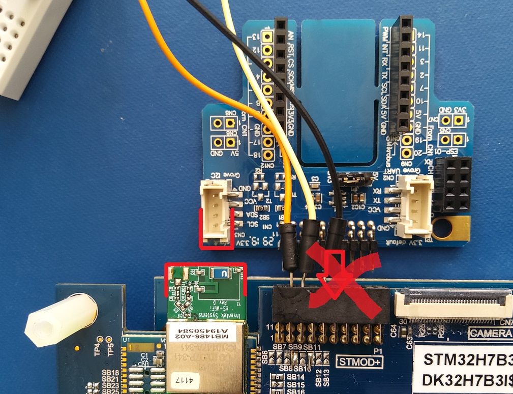
I'll desolder the i2c connector. But what a shame. Even with he connector off, the fan-out will interfere with the WiFi antenna because it's in the keep-out region.


Breaking Out the UART Signals


Back to business. I want to use the UART2 of the controller. And that's broken out to that STMod+ connector.

image


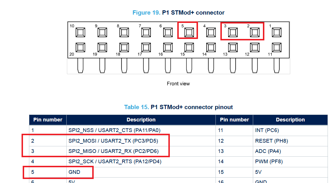
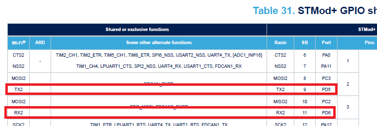
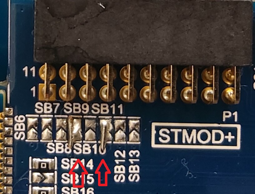
There are multiple options for the pins 2 and 3. To take care that they are connected to the controller UART2 pads, you connect 2 solder bridges:

SB9 for TX, SB11 for RX.


image


This is not hard. I used a little single wire chunk. The better way is to use a 0R resistor. You can also try to just bridge the pads with solder.

image


Adapting the Code to work with UART2

The start point is the project from STM32H7B3I - USB, freeRTOS ,Task Notifications and Interrupts .

You can download the CubeIDE project from there, or try to build from scratch as I did...


Maybe you want to disable the UART1 from the previous exercise if you want, but there's no need.
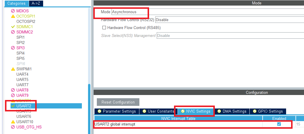
Let's enable UART2.

image

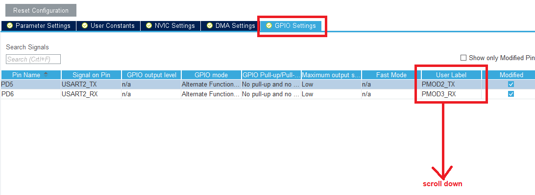
For documentation reasons, I gave the 2 pins a user name.

image


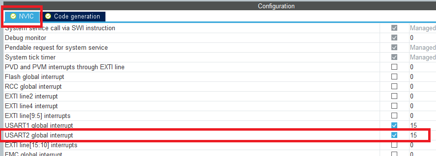
Adapt the interrupts in the NVIC properties:

image


And enable code generation (as we did in the previous post for UART1)
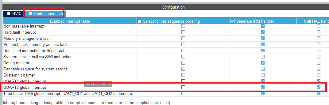
image


Generate the code.


Write the Code


This is exactly the same as in the previous blog, but for UART 2.

I used some compiler defines to make it easy for me to switch betwen UART1 (the USB port) and UART2:


I created a pointer hart that points to the UART handle of choice:


/* USER CODE BEGIN PTD */
#define USE_UART 2
/* USER CODE END PTD */

#if USE_UART == 1
UART_HandleTypeDef *huart = &huart1;
#endif

#if USE_UART == 2
UART_HandleTypeDef *huart = &huart2;
#endif


In the freeRTOS UART task, I adapted 1 line of code - where it was &huar1, it's now the huart pointer:


void TaskUARTListen(void *argument)
{
// ....
    HAL_UART_Receive_IT(huart, in, buffersize);


And in the IRQ handler for UART2, I pasted the same code as I did for UART1 in the previous post:


void USART2_IRQHandler(void)
{
  /* USER CODE BEGIN USART2_IRQn 0 */

  /* USER CODE END USART2_IRQn 0 */
  HAL_UART_IRQHandler(&huart2);
  /* USER CODE BEGIN USART2_IRQn 1 */
  BaseType_t xHigherPriorityTaskWoken = pdFALSE;
  configASSERT( xTaskToNotifyatUARTRx != NULL );
  vTaskNotifyGiveFromISR( xTaskToNotifyatUARTRx, &xHigherPriorityTaskWoken );
//  xTaskToNotifyatUARTRx = NULL;
  portYIELD_FROM_ISR( xHigherPriorityTaskWoken );

  /* USER CODE END USART2_IRQn 1 */
}


That's it, compile and test.


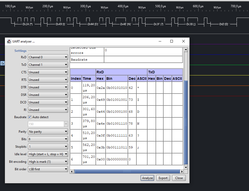
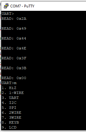
Oh, to test that also the Tx line works, I added these two lines at the start of the program, just before the RTOS scheduler is started:


  uint8_t str[] = "*IDN?;";
  HAL_UART_Transmit(huart, str, sizeof(str), 100);


Both Tx and Rx work. I've tested both directions.

I use a Bus Pirate to emulate the other side of the communication (it's an excellent protocol test tool), and a Papilio Pro FPGA as logic analyser:

imageimage


Related Posts
First Experience with CubeIDE
Create a TouchGFX Project with support for the Designer, CubeIDE and Debugger - Pt 1: Screen Works
Create a TouchGFX Project with support for the Designer, CubeIDE and Debugger - Pt 2: Touch Works
TouchGFX Simple Example: react on a button click
USB, freeRTOS ,Task Notifications and Interrupts
the Development Kit STMod+ Connector and Using UART2
TouchGFX Application Framework: Model, View, Presentation, Message Queue
TouchGFX Application Framework: A Mock GUI - Show Statuses, Switch Screens
TouchGFX Application Framework: MVP and the ModelListener
Write a CubeIDE MX application: Hardware Cryptography with DMA
  • Sign in to reply

Top Comments

  • jomoenginer
    jomoenginer over 5 years ago in reply to Jan Cumps +2
    Yeah, I matched the pin nums. As you pointed out on the Slack channel, the Arduino headers will not work. Wrong pitch. Also, that image from the STM page with the fanout board connected, I think that is…
  • Jan Cumps
    Jan Cumps over 5 years ago +1
    I removed the Grove connector: Even though I took care, one of the unconnected solder pads lifted (you can see it if you look closely under the 4 connected pads - the pad half disappearing under the WiFI…
  • DAB
    DAB over 5 years ago +1
    Great work around Jan. DAB
Parents
  • jomoenginer
    jomoenginer over 5 years ago

    On my board, the fanout board does plugin but is quite snug up against the WiFi module and not completely inserted into the header but all pins seem to be making contact. I suppose an extender would help like 2 of the 1x10 Arduino headers.


    The interesting thing is that the pic for the STM32H7B3i-DK with the Fanout board connected from the STM page shows it plugged into the finer pitch CN3 connector which the User's Guide lists as a Audio connector. I wonder how they tested that.

    • Cancel
    • Vote Up +1 Vote Down
    • Sign in to reply
    • More
    • Cancel
  • Jan Cumps
    Jan Cumps over 5 years ago in reply to jomoenginer

    jomoenginer  wrote:


    On my board, the fanout board does plugin but is quite snug up against the WiFi module and not completely inserted into the header but all pins seem to be making contact. I suppose an extender would help like 2 of the 1x10 Arduino headers.


    Are you sure you have it the right way up? Look at pin 1 and 11 on both printscreens ..

    • Cancel
    • Vote Up +1 Vote Down
    • Sign in to reply
    • More
    • Cancel
  • jomoenginer
    jomoenginer over 5 years ago in reply to Jan Cumps

    Yeah, I matched the pin nums.


    As you pointed out on the Slack channel, the Arduino headers will not work. Wrong pitch.


    Also, that image from the STM page with the fanout board connected, I think that is just a super imposed image that someone placed on the board since the scale of the fanout board does not match it's actual size.  It seems much smaller in the pic.

    • Cancel
    • Vote Up +2 Vote Down
    • Sign in to reply
    • More
    • Cancel
Comment
  • jomoenginer
    jomoenginer over 5 years ago in reply to Jan Cumps

    Yeah, I matched the pin nums.


    As you pointed out on the Slack channel, the Arduino headers will not work. Wrong pitch.


    Also, that image from the STM page with the fanout board connected, I think that is just a super imposed image that someone placed on the board since the scale of the fanout board does not match it's actual size.  It seems much smaller in the pic.

    • Cancel
    • Vote Up +2 Vote Down
    • Sign in to reply
    • More
    • Cancel
Children
No Data
element14 Community

element14 is the first online community specifically for engineers. Connect with your peers and get expert answers to your questions.

  • Members
  • Learn
  • Technologies
  • Challenges & Projects
  • Products
  • Store
  • About Us
  • Feedback & Support
  • FAQs
  • Terms of Use
  • Privacy Policy
  • Legal and Copyright Notices
  • Sitemap
  • Cookies

An Avnet Company © 2025 Premier Farnell Limited. All Rights Reserved.

Premier Farnell Ltd, registered in England and Wales (no 00876412), registered office: Farnell House, Forge Lane, Leeds LS12 2NE.

ICP 备案号 10220084.

Follow element14

  • X
  • Facebook
  • linkedin
  • YouTube