


|
Previous blogs:
FPGA: Making Waves
Introduction
In the last blog, I looked at computing a sinewave using a CORDIC method. It was implemented in a iterated bit-serial fashion to keep the hardware usage low, though it turned out to be more complex than I had anticipated because of some of the fiddly control necessary.
This time I'm going to add a passive analogue reconstruction filter to the output. At the same time, I'll have to do a bit of work on my phase accumulator. In the last blog, I just had it running from -pi/2 to +pi/2 to generate half of the sine, but now I need it to run continuously and generate the actual sinewave.
The Circuit
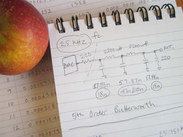
Here's the circuit for the filter I used:
In case you're interested, today's apple is a Cox's Orange Pippin. This one lived up to its name and was a nice orange and red colour.
For the filter, I chose a 5th-order Butterworth low-pass response and designed it by finding the normalised (to 1Hz and 1ohm) capacitor and inductor values in a book and then scaling them appropriately. [I actually worked it out somewhat backwards, because I only had a very limited range of chokes, so I looked for which inductor would give a fairly sensible resistor value for the cut-off frequency I wanted (25kHz) and then calculated the capacitors on the basis I could probably piece them together from parts that I had.]
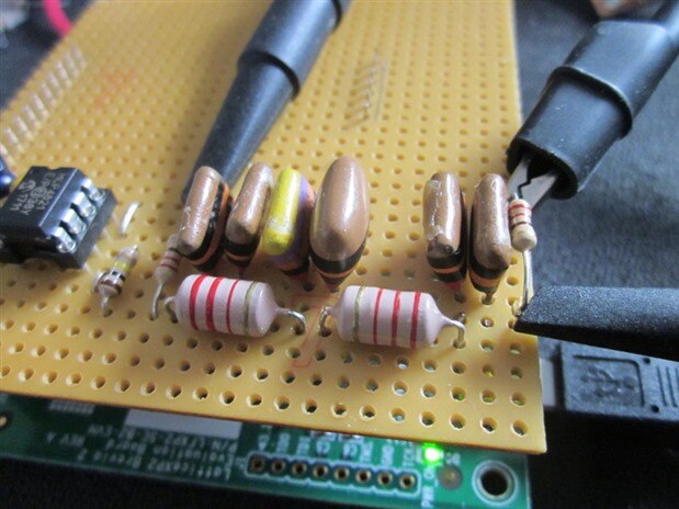
Here it is built on my prototyping board.
You can see that I've paralleled-up capacitors to get the value I wanted. Happily, I found some old 10nF parts that actually measured 9nF and which I could parallel to give 18nF.
Simulated Response
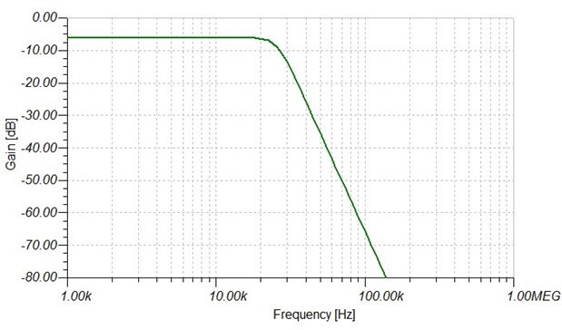
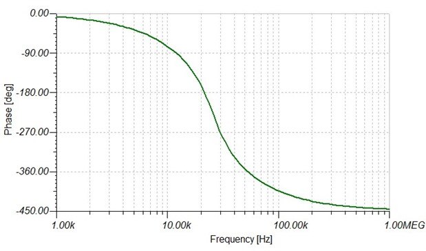
Here's what a simulator gives me for the frequency and phase responses for the component values I've chosen:
Phase Accumulator
I wasn't too sure what to do with the phase accumulator. Working with the interval -pi/2 to pi/2 is awkward, though I suppose there is an argument that, using radians, frequencies then work out neatly and directly. But in an FPGA, it seemed like it might be simpler to scale the input so that I could use binary modulo arithmetic, the modulo arithmetic giving me the wrap-around of the phase for free.
The CORDIC approach I'm using here operates with simple additions and subtractions to iterate to the required angle, so I don't need to scale the input phase from the binary range used by the accumulator to the radian range used by the CORDIC processor, instead I can bake the scale factor into the coefficients and save having the multiply. Effectively, the CORDIC is then doing the multiply for me.
The other thing I have to arrange is to achieve the symmetry to get the other half of the sine which would conflict with simply using modulo arithmetic where I'd just have one half repeating. After a bit of head scratching, I realised that I could operate the binary accumulator over the interval -2 to +2 and use an exclusive or of the top two bits to control whether to use the value directly or to invert the lower part of it. That seems to work, though I haven't convinced myself that it is strictly correct.
The VHDL
------------------------------------------------------------------
--    ***** waves_cordic_sine *****      --
--  15-bit CORDIC sine calculation in serial form (slow!)       --
-- coefficients now normalised for +1 to -1 range               --
-- rather than +pi/2 to -pi/2                                   --
-- to allow for binary modulo arithmetic on phase accumulator   --
------------------------------------------------------------------
-- JC 4th November 2019               --
------------------------------------------------------------------
-- Rev    Date         Comments         --
-- 01     04-Nov-2019            --
------------------------------------------------------------------
library ieee;
use ieee.std_logic_1164.all;
use ieee.std_logic_arith.all;
use ieee.std_logic_unsigned.all;
entity wave_cordic_con is port(
  clk_in:   in std_logic;        --- system clock in (50 MHz oscillator)
  --- DAC connections
  mcp4821_ncs: out std_logic;        --- DAC cs
  mcp4821_sck: out std_logic;        --- DAC sck
  mcp4821_sdi: out std_logic;        --- DAC sdi
  mcp4821_nldac: out std_logic;        --- DAC load
  --- misc control signals on evaluation board that it might be good to hold at fixed levels
  spi_cs:   out std_logic;        ---
  hold_n:   out std_logic;        ---
  sram_cen:  out std_logic;        ---
  sram_oen:  out std_logic;        ---
  sram_wen:  out std_logic;        ---
  uart_tx:  out std_logic);        ---

end wave_cordic_con;
architecture arch_wave_cordic of wave_cordic_con is
signal start_count: std_logic_vector (1 downto 0);
signal start_reset: std_logic;
signal spi_send, spi_send_plus_one, spi_ncs, spi_ncs_del: std_logic;
signal spi_output_sr_bit_count: std_logic_vector (5 downto 0);
signal spi_output_sr: std_logic_vector (15 downto 0);
signal interval_count: std_logic_vector (8 downto 0);
signal acc_count: std_logic_vector (7 downto 0);
signal cordic_reset,cordic_enable, cordic_dir: std_logic;
signal cordic_count: std_logic_vector (7 downto 0);
signal adder_out: std_logic_vector (31 downto 0);
signal add_sub_1_out, add_sub_2_out, add_sub_3_out: std_logic_vector (0 downto 0);
signal mux_select: std_logic_vector (3 downto 0);
signal mux_count: std_logic_vector (3 downto 0);
signal sine_tap_value, cos_tap_value: std_logic_vector (0 downto 0);
signal theta: std_logic_vector (15 downto 0);
signal phase_acc: std_logic_vector (31 downto 0);
signal phase_increment: std_logic_vector (31 downto 0);
signal sine_value: std_logic_vector (15 downto 0);
signal cos_value: std_logic_vector (15 downto 0);
signal angle_value: std_logic_vector (15 downto 0);
signal osc_reset: std_logic_vector (1 downto 0);
signal rom_out: std_logic_vector (0 downto 0);
signal carry_1_in, carry_2_in, carry_3_in: std_logic;
signal carry_1_out, carry_2_out, carry_3_out: std_logic;
signal sine_sign_extend, cos_sign_extend: std_logic;
signal sine_select: std_logic;
--- declare the adder/subractor and the table modules as components
component add_sub_module is
    port (
        DataA: in  std_logic_vector(0 downto 0);
        DataB: in  std_logic_vector(0 downto 0);
        Cin: in  std_logic;
        Add_Sub: in  std_logic;
        Result: out  std_logic_vector(0 downto 0);
        Cout: out  std_logic);
end component;
component rom_module is
    port (
        Address: in  std_logic_vector(7 downto 0);
        Q: out  std_logic_vector(0 downto 0));
end component;
component add_module is
    port (
        DataA: in  std_logic_vector(31 downto 0);
        DataB: in  std_logic_vector(31 downto 0);
        Result: out  std_logic_vector(31 downto 0));
end component;
begin
 wave_cordic_stuff: process (clk_in)
  begin
   if (clk_in'event and clk_in='1') then
    --- start reset
    if (start_count(1 downto 0) /= b"11") then
     start_count(1 downto 0) <= start_count(1 downto 0) + 1;
    end if;
    if (start_count(1 downto 0) = b"10") then
     start_reset <= '1';
    else
     start_reset <= '0';
    end if;
    --- interval_count counts at the clock rate (50MHz)
    --- counts down by 500, so spi_send occurs every 10us (100kHz)
    if (interval_count(8 downto 0) = b"000000000") then     --- if zero
     interval_count(8 downto 0) <= b"111110011";      --- preset to 499
     spi_send <= '1';
    else
     interval_count(8 downto 0) <= interval_count(8 downto 0) - 1; --- count down
     spi_send <= '0';
    end if;

    spi_send_plus_one <= spi_send;       --- spi_send delayed by one clock
    --- spi ncs goes low when triggered by spi_send, goes hi again when bitcount reaches 31

    if (spi_send = '1') then
     spi_ncs <= '0';
    elsif (spi_output_sr_bit_count(5 downto 0) = b"111111") then
     spi_ncs <= '1';
    end if;

    spi_ncs_del <= spi_ncs;
    --- cordic reset occurs at end of spi cs
    --- this starts the CORDIC calculation for the next sine
    if (spi_ncs = '1' and spi_ncs_del = '0') then
     cordic_reset <= '1';
    else
     cordic_reset <= '0';
    end if;
    --- cordic enable and cordic count
    --- there are 15 cycles of 16 bits, so count goes to 240
    --- low half of count is the bit, high part is the cycle

    if (cordic_reset = '1') then
     cordic_enable <= '1';
---    elsif (cordic_count(7 downto 0) = b"00001111") then
    elsif (cordic_count(7 downto 0) = b"11011111") then
     cordic_enable <= '0';
    end if;

    if (cordic_enable = '1') then
     cordic_count(7 downto 0) <= cordic_count(7 downto 0) + 1;
    else
     cordic_count(7 downto 0) <= b"00000000";
    end if;

    --- spi output bit count only counts when enable spi cs is low

    if (spi_ncs = '0') then
     spi_output_sr_bit_count(5 downto 0) <= spi_output_sr_bit_count(5 downto 0) + 1;
    else
     spi_output_sr_bit_count(5 downto 0) <= b"000000";
    end if;
    --- phase accumulator
    --- addition of increment done just before CORDIC calculation
    --- S1.30
    if (start_reset = '1') then
     phase_acc(31 downto 0) <= b"0_0_000000000000000000000000000000"; --- at start set to zero
    elsif(spi_send = '1') then
     phase_acc(31 downto 0) <= adder_out(31 downto 0);    --- store addition of increment to current phase
    end if;
    --- on next cycle after spi_send, theta is derived from the phase accumulator.
    --- values between -1 and +1 are unchanged, outside that, they fold in
    --- to get the symmetry on the waveform
    if(spi_send_plus_one = '1') then
     if((phase_acc(31) xor phase_acc(30)) = '0') then
      theta(15) <= phase_acc(31);
      theta(14 downto 0) <= phase_acc(30 downto 16);
     else
      theta(15) <= phase_acc(31);
      theta(14 downto 0) <= not phase_acc(30 downto 16);
     end if;
    end if;
    --- CORDIC algorithm
    --- Implemented as bit-serial arithmetic (this is my choice for minimal hardware - not inherent in method).
    --- Each variable gets rotated out of shift register, with single bit at a time being presented
    --- to a 1-bit adder/subtractor, and the result shifted back in the other end.
    --- Cos start value is prescaled to save having to compensate with a
    --- multiplication at the end.
    --- angle_value is preset to the required phase, the algorithm then aims for an angle value of zero.
    --- Which side of zero we are on is easy to test for as it just entails looking at the resulting
    --- angle_value sign bit and using that to control whether to add or subtract on the next iteration.
    if (cordic_reset = '1') then
     sine_value(15 downto 0) <= b"0_0_00000000000000";   --- sin starts at 0
     cos_value(15 downto 0) <= b"0_1_00110110111000";   --- cos = 1/An (An is gain for n iterations)
     angle_value(15 downto 0) <= theta(15 downto 0);
    elsif (cordic_enable = '1') then
     cos_value(14 downto 0) <= cos_value(15 downto 1);   --- rotate right through add/sub
     cos_value(15) <= add_sub_1_out(0);
     sine_value(14 downto 0) <= sine_value(15 downto 1);   --- rotate right through add/sub
     sine_value(15) <= add_sub_2_out(0);
     angle_value(14 downto 0) <= angle_value(15 downto 1);  --- rotate right through add/sub
     angle_value(15) <= add_sub_3_out(0);
    end if;
    if (cordic_reset = '1') then
     cos_sign_extend <= '0';
     sine_sign_extend <= '0';
     cordic_dir <= theta(15);  --- initial direction depends on sign of angle
     carry_1_in <= not theta(15); --- sense of initial carry depends on whether next cycle is add or subtract
     carry_2_in <= theta(15);
     carry_3_in <= not theta(15);
    elsif (cordic_count(3 downto 0) = b"1111") then --- at end of word
     cos_sign_extend <= add_sub_1_out(0); --- sign of result is stored for next cycle
     sine_sign_extend <= add_sub_2_out(0); --- ... for use by sign-extension
     cordic_dir <= add_sub_3_out(0);   --- sign of angle determines add/sub for next cycle
     carry_1_in <= not add_sub_3_out(0);  --- set to no carry or no borrow at start
     carry_2_in <= add_sub_3_out(0);
     carry_3_in <= not add_sub_3_out(0);
    else
     carry_1_in <= carry_1_out;  --- whilst rotating, carry is from the last bit-add or bit-subtract
     carry_2_in <= carry_2_out;
     carry_3_in <= carry_3_out;
    end if;
    if (cordic_reset = '1') then
     mux_count <= b"0000";  ---
    elsif (cordic_count(3 downto 0) = b"1111") then
     mux_count <= cordic_count(7 downto 4) + 1;  ---
    elsif (mux_count(3 downto 0) /= b"1111") then
     mux_count <= mux_count + 1;
    end if;

    if (cordic_reset = '1') then
     mux_select <= b"0000";  --- s/r start 'tap' for next cycle
    elsif (cordic_reset = '1' or cordic_count(3 downto 0) = b"1111") then
     mux_select <= cordic_count(7 downto 4) + 1;  --- s/r start 'tap' for next cycle
    elsif (mux_count(3 downto 0) = b"1111") then
     mux_select <= b"1111";      --- ...selects sign extend instead for rest
    end if;
    --- spi output shift register

    if (spi_send = '1') then             --- load...
     spi_output_sr(10 downto 0) <= sine_value(14 downto 4);    ---  use sine value
     spi_output_sr(11) <= not sine_value(15);       --- inverse of sign bit
     spi_output_sr(15 downto 12) <= b"0011";         ---   dac control bits
    elsif (spi_ncs = '0' and spi_output_sr_bit_count(1 downto 0) = b"11") then --- shift...
     spi_output_sr(15 downto 1) <= spi_output_sr(14 downto 0);    ---  the register contents
     spi_output_sr(0) <= '0';
    end if;
   end if;
   --- multiplexers to tap the sine and cos shift registers
   --- (as well as doing the shift, these deal with the sign-extend
   --- for 2's complement arithmetic)
   case mux_select(3 downto 0) is
    when b"0000" => sine_tap_value(0) <= sine_value(0);
    when b"0001" => sine_tap_value(0) <= sine_value(1);
    when b"0010" => sine_tap_value(0) <= sine_value(2);
    when b"0011" => sine_tap_value(0) <= sine_value(3);
    when b"0100" => sine_tap_value(0) <= sine_value(4);
    when b"0101" => sine_tap_value(0) <= sine_value(5);
    when b"0110" => sine_tap_value(0) <= sine_value(6);
    when b"0111" => sine_tap_value(0) <= sine_value(7);
    when b"1000" => sine_tap_value(0) <= sine_value(8);
    when b"1001" => sine_tap_value(0) <= sine_value(9);
    when b"1010" => sine_tap_value(0) <= sine_value(10);
    when b"1011" => sine_tap_value(0) <= sine_value(11);
    when b"1100" => sine_tap_value(0) <= sine_value(12);
    when b"1101" => sine_tap_value(0) <= sine_value(13);
    when b"1110" => sine_tap_value(0) <= sine_value(14);
    when b"1111" => sine_tap_value(0) <= sine_sign_extend;
    when others => sine_tap_value(0) <= sine_sign_extend;
   end case;
   case mux_select(3 downto 0) is
    when b"0000" => cos_tap_value(0) <= cos_value(0);
    when b"0001" => cos_tap_value(0) <= cos_value(1);
    when b"0010" => cos_tap_value(0) <= cos_value(2);
    when b"0011" => cos_tap_value(0) <= cos_value(3);
    when b"0100" => cos_tap_value(0) <= cos_value(4);
    when b"0101" => cos_tap_value(0) <= cos_value(5);
    when b"0110" => cos_tap_value(0) <= cos_value(6);
    when b"0111" => cos_tap_value(0) <= cos_value(7);
    when b"1000" => cos_tap_value(0) <= cos_value(8);
    when b"1001" => cos_tap_value(0) <= cos_value(9);
    when b"1010" => cos_tap_value(0) <= cos_value(10);
    when b"1011" => cos_tap_value(0) <= cos_value(11);
    when b"1100" => cos_tap_value(0) <= cos_value(12);
    when b"1101" => cos_tap_value(0) <= cos_value(13);
    when b"1110" => cos_tap_value(0) <= cos_value(14);
    when b"1111" => cos_tap_value(0) <= cos_sign_extend;
    when others => cos_tap_value(0) <= cos_sign_extend;
   end case;
   --- phase increment for testing
   phase_increment(31 downto 0) <= b"0_00_01100110011001100110011001100"; ---
   --- wiring the DAC I/O pins

   mcp4821_ncs <= spi_ncs;
   mcp4821_sck <= spi_output_sr_bit_count(1);
   mcp4821_sdi <= spi_output_sr(15);
   mcp4821_nldac <= '0';

   --- hold these device control pins at a fixed level to stop them flapping around
   spi_cs <= '1';
   hold_n <= '1';
   sram_cen <= '1';
   sram_oen <= '1';
   sram_wen <= '1';
   uart_tx <= '1';
  end process wave_cordic_stuff;

  --- instantiate the adder-subtractors, adder, and the ROM table holding the inverse tangent values

  add_sub_1: add_sub_module  --- cosine
   port map(
    DataA => cos_value(0 downto 0),
    DataB => sine_tap_value(0 downto 0),
    Cin => carry_1_in,
    Add_Sub => cordic_dir,
    Result => add_sub_1_out(0 downto 0),
    Cout => carry_1_out);

  add_sub_2: add_sub_module  --- sine
   port map(
    DataA => sine_value(0 downto 0),
    DataB => cos_tap_value(0 downto 0),
    Cin => carry_2_in,
    Add_Sub => not cordic_dir,
    Result => add_sub_2_out(0 downto 0),
    Cout => carry_2_out);
  add_sub_3: add_sub_module  ---angle
   port map(
    DataA => angle_value(0 downto 0),
    DataB => rom_out(0 downto 0),
    Cin => carry_3_in,
    Add_Sub => cordic_dir,
    Result => add_sub_3_out(0 downto 0),
    Cout => carry_3_out);

  rom_module1: rom_module   --- inverse-tangent table (bit serial, 256 bits, lsb first)
   port map(
    Address => cordic_count(7 downto 0),
    Q => rom_out(0 downto 0));
  add_1: add_module  --- phase accumulator calculation
   port map(
    DataA => phase_acc(31 downto 0),
    DataB => phase_increment(31 downto 0),
    Result => adder_out(31 downto 0));
end arch_wave_cordic;
This is the ROM table holding the inverse tangent values. It's a 256x1 ROM and the first bit out is the lsb one.
1
0
1
0
0
0
1
1
0
0
0
0
0
1
0
0
0
0
0
1
1
0
1
0
1
1
0
0
1
0
0
0
1
0
0
1
1
1
0
0
0
1
0
1
0
0
0
0
0
0
0
0
1
1
0
0
1
0
1
0
0
0
0
0
1
1
0
1
1
0
0
1
0
1
0
0
0
0
0
0
0
1
1
1
0
0
1
0
1
0
0
0
0
0
0
0
1
1
1
0
0
1
0
1
0
0
0
0
0
0
0
0
1
1
0
0
1
0
1
0
0
0
0
0
0
0
0
0
0
1
0
1
0
1
0
0
0
0
0
0
0
0
0
0
1
0
1
0
1
0
0
0
0
0
0
0
0
0
0
0
0
1
0
1
0
0
0
0
0
0
0
0
0
0
0
0
1
0
1
0
0
0
0
0
0
0
0
0
0
0
0
0
1
1
0
0
0
0
0
0
0
0
0
0
0
0
0
0
1
0
0
0
0
0
0
0
0
0
0
0
0
0
0
0
1
0
0
0
0
0
0
0
0
0
0
0
0
0
0
0
1
0
0
0
0
0
0
0
0
0
0
0
0
0
0
0
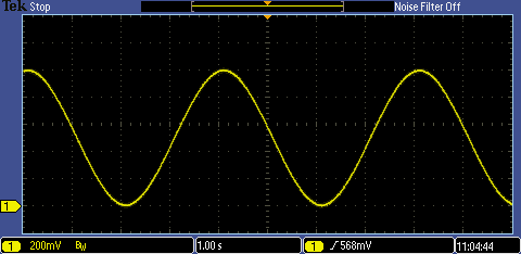
Testing
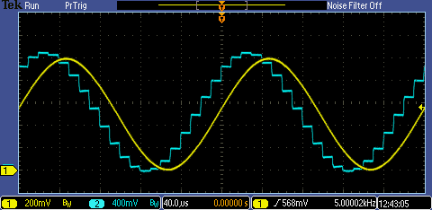
Here's how it looks on the oscilloscope. The blue trace is the output of the DAC, the yellow the filtered waveform. It was supposed to be 10kHz - I forgot about the extra factor of two that I had built in.
The amplitude is diminished slightly over the gain of x0.5 we'd expect from the equal-value resistors at each end of the filter. That's probably the sinc roll-off from the first-order hold response of the DAC which I haven't tried to compensate for, either in the design of the analogue filter or by filtering digitally with the inverse response in the FPGA. I'll add it to the list for future blogs.
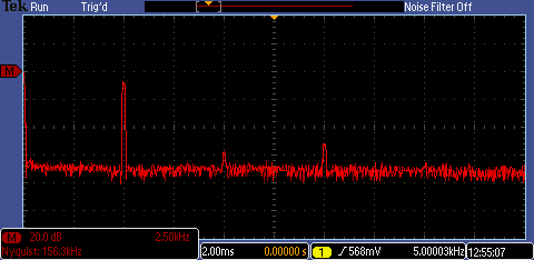
Out of curiosity, I tried the filtered sine with the 'scope's FFT. That shows a fair bit of 3rd harmonic and some 2nd, so it might be that the way I'm folding the accumulator values isn't quite right.
Update 9th November
I've been looking at the phase accumulator and I did get it wrong. To get the symmetry, I should have complemented and added one rather than just complemented. It didn't make much difference in practice, though (because of the large, 32-bit phase accumulator). With my 5kHz waveform, a difference of one over half the cycle is next to nothing and doesn't notice at all in the end result. But, correcting that showed up a more subtle problem.
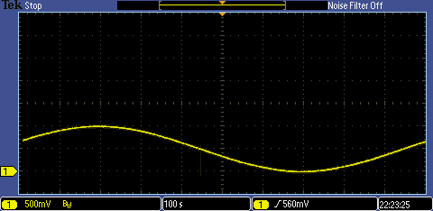
I thought I'd have a look at generating a really slow waveform. I'd already done some calculations for a 2Hz sinewave, so I put in the phase increment and this was the result:
Hmm, got that wrong! My calculations had been for the fast cordic variant, with a sample rate of 50Msps, and not the 100ksps I'm using with the SPI DAC, so the end result was this sine with period of over 16 minutes. I let it run for a whole cycle so that you could see the trace. It does show at least one advantage of a digitally-generated waveform: that result would be extremely hard to achieve with an analogue oscillator.
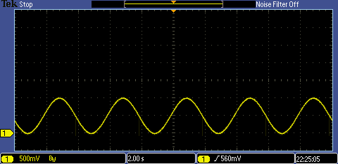
What caught my attention was what appears to be a glitch. Well, it looks like a glitch, but if I increase the size of the phase increment and generate a 0.25Hz waveform, we can see that it occurs in the same place every cycle.
My tests for whether to leave the phase alone, or do the complement and add one, needed an additional test so that they get the very negative-most value right (it needs to be treated as a special case, unfortunately).
I now have this for the 0.25Hz waveform
That's quite mesmerising to watch, a bit like looking at a pendulum swinging back and forth as it gets drawn on the righthand edge of the oscilloscope screen.
There's been next to no change of the spectrum, so it doesn't look like the distortion is coming from the phase calculations.
Here's the reworked code, in case you're interested in looking at it. No warranty. No guarantee. No fitness for any purpose, and all that kind of thing.
----------------------------------------------------------------------
--              ***** waves_cordic_sine *****                       --
-- 15-bit CORDIC sine calculation in serial form (slow!)            --
-- coefficients now normalised for +1 to -1 range                --
-- rather than +pi/2 to -pi/2                                    --
-- to allow for binary modulo arithmetic on phase accumulator       --
----------------------------------------------------------------------
-- JC 4th November 2019                                             --
----------------------------------------------------------------------
-- Rev    Date         Comments                                     --
-- 01     04-Nov-2019                                               --
-- 02     09-Nov-2019 Reworked derivation of theta from phase_acc   --
----------------------------------------------------------------------
library ieee;
use ieee.std_logic_1164.all;
use ieee.std_logic_arith.all;
use ieee.std_logic_unsigned.all;
entity wave_cordic_con is port(
  clk_in:   in std_logic;        --- system clock in (50 MHz oscillator)
  --- DAC connections
  mcp4821_ncs: out std_logic;        --- DAC cs
  mcp4821_sck: out std_logic;        --- DAC sck
  mcp4821_sdi: out std_logic;        --- DAC sdi
  mcp4821_nldac: out std_logic;        --- DAC load
  --- misc control signals on evaluation board that it might be good to hold at fixed levels
  spi_cs:   out std_logic;        ---
  hold_n:   out std_logic;        ---
  sram_cen:  out std_logic;        ---
  sram_oen:  out std_logic;        ---
  sram_wen:  out std_logic;        ---
  uart_tx:  out std_logic);        ---

end wave_cordic_con;
architecture arch_wave_cordic of wave_cordic_con is
signal start_count: std_logic_vector (1 downto 0);
signal start_reset: std_logic;
signal spi_send, spi_send_plus_one, spi_ncs, spi_ncs_del: std_logic;
signal spi_output_sr_bit_count: std_logic_vector (5 downto 0);
signal spi_output_sr: std_logic_vector (15 downto 0);
signal interval_count: std_logic_vector (8 downto 0);
signal acc_count: std_logic_vector (7 downto 0);
signal cordic_reset,cordic_enable, cordic_dir: std_logic;
signal cordic_count: std_logic_vector (7 downto 0);
signal adder_out: std_logic_vector (31 downto 0);
signal add_sub_1_out, add_sub_2_out, add_sub_3_out: std_logic_vector (0 downto 0);
signal mux_select: std_logic_vector (3 downto 0);
signal mux_count: std_logic_vector (3 downto 0);
signal sine_tap_value, cos_tap_value: std_logic_vector (0 downto 0);
signal theta: std_logic_vector (15 downto 0);
signal phase_acc: std_logic_vector (31 downto 0);
signal phase_increment: std_logic_vector (31 downto 0);
signal sine_value: std_logic_vector (15 downto 0);
signal cos_value: std_logic_vector (15 downto 0);
signal angle_value: std_logic_vector (15 downto 0);
signal osc_reset: std_logic_vector (1 downto 0);
signal rom_out: std_logic_vector (0 downto 0);
signal carry_1_in, carry_2_in, carry_3_in: std_logic;
signal carry_1_out, carry_2_out, carry_3_out: std_logic;
signal sine_sign_extend, cos_sign_extend: std_logic;
signal sine_select: std_logic;
--- declare the adder/subractor and the table modules as components
component add_sub_module is
    port (
        DataA: in  std_logic_vector(0 downto 0);
        DataB: in  std_logic_vector(0 downto 0);
        Cin: in  std_logic;
        Add_Sub: in  std_logic;
        Result: out  std_logic_vector(0 downto 0);
        Cout: out  std_logic);
end component;
component rom_module is
    port (
        Address: in  std_logic_vector(7 downto 0);
        Q: out  std_logic_vector(0 downto 0));
end component;
component add_module is
    port (
        DataA: in  std_logic_vector(31 downto 0);
        DataB: in  std_logic_vector(31 downto 0);
        Result: out  std_logic_vector(31 downto 0));
end component;
begin
 wave_cordic_stuff: process (clk_in)
  begin
   if (clk_in'event and clk_in='1') then
    --- start reset
    if (start_count(1 downto 0) /= b"11") then
     start_count(1 downto 0) <= start_count(1 downto 0) + 1;
    end if;
    if (start_count(1 downto 0) = b"10") then
     start_reset <= '1';
    else
     start_reset <= '0';
    end if;
    --- interval_count counts at the clock rate (50MHz)
    --- counts down by 500, so spi_send occurs every 10us (100kHz)
    if (interval_count(8 downto 0) = b"000000000") then     --- if zero
     interval_count(8 downto 0) <= b"111110011";      --- preset to 499
     spi_send <= '1';
    else
     interval_count(8 downto 0) <= interval_count(8 downto 0) - 1; --- count down
     spi_send <= '0';
    end if;

    spi_send_plus_one <= spi_send;       --- spi_send delayed by one clock
    --- spi ncs goes low when triggered by spi_send, goes hi again when bitcount reaches 31

    if (spi_send = '1') then
     spi_ncs <= '0';
    elsif (spi_output_sr_bit_count(5 downto 0) = b"111111") then
     spi_ncs <= '1';
    end if;

    spi_ncs_del <= spi_ncs;
    --- cordic reset occurs at end of spi cs
    --- this starts the CORDIC calculation for the next sine
    if (spi_ncs = '1' and spi_ncs_del = '0') then
     cordic_reset <= '1';
    else
     cordic_reset <= '0';
    end if;
    --- cordic enable and cordic count
    --- there are 15 cycles of 16 bits, so count goes to 240
    --- low half of count is the bit, high part is the cycle

    if (cordic_reset = '1') then
     cordic_enable <= '1';
---    elsif (cordic_count(7 downto 0) = b"00001111") then
    elsif (cordic_count(7 downto 0) = b"11011111") then
     cordic_enable <= '0';
    end if;

    if (cordic_enable = '1') then
     cordic_count(7 downto 0) <= cordic_count(7 downto 0) + 1;
    else
     cordic_count(7 downto 0) <= b"00000000";
    end if;

    --- spi output bit count only counts when enable spi cs is low

    if (spi_ncs = '0') then
     spi_output_sr_bit_count(5 downto 0) <= spi_output_sr_bit_count(5 downto 0) + 1;
    else
     spi_output_sr_bit_count(5 downto 0) <= b"000000";
    end if;
    --- phase accumulator
    --- addition of increment done just before CORDIC calculation
    --- S1.30
    if (start_reset = '1') then
     phase_acc(31 downto 0) <= b"0_0_000000000000000000000000000000"; --- at start set to zero
    elsif(spi_send = '1') then
     phase_acc(31 downto 0) <= adder_out(31 downto 0);    --- store addition of increment to current phase
    end if;
    --- on next cycle after spi_send, theta is derived from the phase accumulator.
    --- values between -1 and +1 are unchanged, outside that, they fold in
    --- to get the symmetry on the waveform
    if(spi_send_plus_one = '1') then
     if(phase_acc(31 downto 16) = b"1000000000000000") then
      theta(15) <= not phase_acc(31);
     else
      theta(15) <= phase_acc(31);
     end if;

     if((phase_acc(31) xor phase_acc(30)) = '0') then
      theta(14 downto 0) <= phase_acc(30 downto 16);
     else
      theta(14 downto 0) <= (not phase_acc(30 downto 16)) + 1;
     end if;
    end if;

    --- CORDIC algorithm
    --- Implemented as bit-serial arithmetic (this is my choice for minimal hardware - not inherent in method).
    --- Each variable gets rotated out of shift register, with single bit at a time being presented
    --- to a 1-bit adder/subtractor, and the result shifted back in the other end.
    --- Cos start value is prescaled to save having to compensate with a
    --- multiplication at the end.
    --- angle_value is preset to the required phase, the algorithm then aims for an angle value of zero.
    --- Which side of zero we are on is easy to test for as it just entails looking at the resulting
    --- angle_value sign bit and using that to control whether to add or subtract on the next iteration.
    if (cordic_reset = '1') then
     sine_value(15 downto 0) <= b"0_0_00000000000000";   --- sin starts at 0
     cos_value(15 downto 0) <= b"0_1_00110110111000";   --- cos = 1/An (An is gain for n iterations)
---     cos_value(15 downto 0) <= b"0_0_10011011011100";   --- cos = 1/An (An is gain for n iterations)
     angle_value(15 downto 0) <= theta(15 downto 0);
    elsif (cordic_enable = '1') then
     cos_value(14 downto 0) <= cos_value(15 downto 1);   --- rotate right through add/sub
     cos_value(15) <= add_sub_1_out(0);
     sine_value(14 downto 0) <= sine_value(15 downto 1);   --- rotate right through add/sub
     sine_value(15) <= add_sub_2_out(0);
     angle_value(14 downto 0) <= angle_value(15 downto 1);  --- rotate right through add/sub
     angle_value(15) <= add_sub_3_out(0);
    end if;
    if (cordic_reset = '1') then
     cos_sign_extend <= '0';
     sine_sign_extend <= '0';
     cordic_dir <= theta(15);  --- initial direction depends on sign of angle
     carry_1_in <= not theta(15); --- sense of initial carry depends on whether next cycle is add or subtract
     carry_2_in <= theta(15);
     carry_3_in <= not theta(15);
    elsif (cordic_count(3 downto 0) = b"1111") then --- at end of word
     cos_sign_extend <= add_sub_1_out(0); --- sign of result is stored for next cycle
     sine_sign_extend <= add_sub_2_out(0); --- ... for use by sign-extension
     cordic_dir <= add_sub_3_out(0);   --- sign of angle determines add/sub for next cycle
     carry_1_in <= not add_sub_3_out(0);  --- set to no carry or no borrow at start
     carry_2_in <= add_sub_3_out(0);
     carry_3_in <= not add_sub_3_out(0);
    else
     carry_1_in <= carry_1_out;  --- whilst rotating, carry is from the last bit-add or bit-subtract
     carry_2_in <= carry_2_out;
     carry_3_in <= carry_3_out;
    end if;
    if (cordic_reset = '1') then
     mux_count <= b"0000";  ---
    elsif (cordic_count(3 downto 0) = b"1111") then
     mux_count <= cordic_count(7 downto 4) + 1;  ---
    elsif (mux_count(3 downto 0) /= b"1111") then
     mux_count <= mux_count + 1;
    end if;

    if (cordic_reset = '1') then
     mux_select <= b"0000";  --- s/r start 'tap' for next cycle
    elsif (cordic_reset = '1' or cordic_count(3 downto 0) = b"1111") then
     mux_select <= cordic_count(7 downto 4) + 1;  --- s/r start 'tap' for next cycle
    elsif (mux_count(3 downto 0) = b"1111") then
     mux_select <= b"1111";      --- ...selects sign extend instead for rest
    end if;
    --- spi output shift register

    if (spi_send = '1') then             --- load...
     spi_output_sr(10 downto 0) <= sine_value(14 downto 4);    ---  use sine value
     spi_output_sr(11) <= not sine_value(15);       --- inverse of sign bit
     spi_output_sr(15 downto 12) <= b"0011";         ---   dac control bits
    elsif (spi_ncs = '0' and spi_output_sr_bit_count(1 downto 0) = b"11") then --- shift...
     spi_output_sr(15 downto 1) <= spi_output_sr(14 downto 0);    ---  the register contents
     spi_output_sr(0) <= '0';
    end if;
   end if;
   --- multiplexers to tap the sine and cos shift registers
   --- (as well as doing the shift, these deal with the sign-extend
   --- for 2's complement arithmetic)
   case mux_select(3 downto 0) is
    when b"0000" => sine_tap_value(0) <= sine_value(0);
    when b"0001" => sine_tap_value(0) <= sine_value(1);
    when b"0010" => sine_tap_value(0) <= sine_value(2);
    when b"0011" => sine_tap_value(0) <= sine_value(3);
    when b"0100" => sine_tap_value(0) <= sine_value(4);
    when b"0101" => sine_tap_value(0) <= sine_value(5);
    when b"0110" => sine_tap_value(0) <= sine_value(6);
    when b"0111" => sine_tap_value(0) <= sine_value(7);
    when b"1000" => sine_tap_value(0) <= sine_value(8);
    when b"1001" => sine_tap_value(0) <= sine_value(9);
    when b"1010" => sine_tap_value(0) <= sine_value(10);
    when b"1011" => sine_tap_value(0) <= sine_value(11);
    when b"1100" => sine_tap_value(0) <= sine_value(12);
    when b"1101" => sine_tap_value(0) <= sine_value(13);
    when b"1110" => sine_tap_value(0) <= sine_value(14);
    when b"1111" => sine_tap_value(0) <= sine_sign_extend;
    when others => sine_tap_value(0) <= sine_sign_extend;
   end case;
   case mux_select(3 downto 0) is
    when b"0000" => cos_tap_value(0) <= cos_value(0);
    when b"0001" => cos_tap_value(0) <= cos_value(1);
    when b"0010" => cos_tap_value(0) <= cos_value(2);
    when b"0011" => cos_tap_value(0) <= cos_value(3);
    when b"0100" => cos_tap_value(0) <= cos_value(4);
    when b"0101" => cos_tap_value(0) <= cos_value(5);
    when b"0110" => cos_tap_value(0) <= cos_value(6);
    when b"0111" => cos_tap_value(0) <= cos_value(7);
    when b"1000" => cos_tap_value(0) <= cos_value(8);
    when b"1001" => cos_tap_value(0) <= cos_value(9);
    when b"1010" => cos_tap_value(0) <= cos_value(10);
    when b"1011" => cos_tap_value(0) <= cos_value(11);
    when b"1100" => cos_tap_value(0) <= cos_value(12);
    when b"1101" => cos_tap_value(0) <= cos_value(13);
    when b"1110" => cos_tap_value(0) <= cos_value(14);
    when b"1111" => cos_tap_value(0) <= cos_sign_extend;
    when others => cos_tap_value(0) <= cos_sign_extend;
   end case;
   --- phase increment for testing
---   phase_increment(31 downto 0) <= b"0_00_01100110011001100110011001100"; --- 5kHz
   phase_increment(31 downto 0) <= b"0_00_00000000000000010100111110001"; --- 0.25Hz
   --- wiring the DAC I/O pins

   mcp4821_ncs <= spi_ncs;
   mcp4821_sck <= spi_output_sr_bit_count(1);
   mcp4821_sdi <= spi_output_sr(15);
   mcp4821_nldac <= '0';

   --- hold these device control pins at a fixed level to stop them flapping around
   spi_cs <= '1';
   hold_n <= '1';
   sram_cen <= '1';
   sram_oen <= '1';
   sram_wen <= '1';
   uart_tx <= '1';
  end process wave_cordic_stuff;

  --- instantiate the adder-subtractors, adder, and the ROM table holding the inverse tangent values

  add_sub_1: add_sub_module  --- cosine
   port map(
    DataA => cos_value(0 downto 0),
    DataB => sine_tap_value(0 downto 0),
    Cin => carry_1_in,
    Add_Sub => cordic_dir,
    Result => add_sub_1_out(0 downto 0),
    Cout => carry_1_out);

  add_sub_2: add_sub_module  --- sine
   port map(
    DataA => sine_value(0 downto 0),
    DataB => cos_tap_value(0 downto 0),
    Cin => carry_2_in,
    Add_Sub => not cordic_dir,
    Result => add_sub_2_out(0 downto 0),
    Cout => carry_2_out);
  add_sub_3: add_sub_module  ---angle
   port map(
    DataA => angle_value(0 downto 0),
    DataB => rom_out(0 downto 0),
    Cin => carry_3_in,
    Add_Sub => cordic_dir,
    Result => add_sub_3_out(0 downto 0),
    Cout => carry_3_out);

  rom_module1: rom_module   --- inverse-tangent table (bit serial, 256 bits, lsb first)
   port map(
    Address => cordic_count(7 downto 0),
    Q => rom_out(0 downto 0));
  add_1: add_module  --- phase accumulator calculation
   port map(
    DataA => phase_acc(31 downto 0),
    DataB => phase_increment(31 downto 0),
    Result => adder_out(31 downto 0));
end arch_wave_cordic;
(Sorry the formatting is a bit of a mess. I'm copying from the Diamond editor window, but obviously tabs and whatnot get lost or end up with other default values.)
phase_acc is the logic vector that accumulates the phase. The most significant part (considered as sign, one whole bit, and the rest as fraction - so an interval of -2 to +2) gets mangled (for the symmetry) into theta which is the phase given to the CORDIC routine. Theta is then over the interval -1 to +1, represented as a two's complement, fractional binary number.
As far as the CORDIC routines are concerned, they're still working over the interval -pi/2 to +pi/2 radians (-90 to +90 degrees) because I've scaled the inverse tangent values appropriately to compensate for the smaller range [I can do that because the angle operation is linear].
Conclusion
The big problem I'm finding with all this is that there are too many interesting topics to explore. If you're working, you naturally keep a tight focus on the spec and where you're off to, but here I'm rushing off in all directions and trying to do too many things at once. I can't quite decide what's next. Possibly fast CORDIC, though I'm tempted to look at either random sequences or computation of logs/exponentials.
[1] http://www.latticesemi.com/en/Products/DevelopmentBoardsAndKits/LatticeXP2Brevia2DevelopmentKit.aspx |
Top Comments