Table of Contents
- Introduction
- Getting Started
- Build and Wiring
- Programming with Vivado Design Suite
- Adding the PIR Motion Sensor
- Experimenting with Automatic Sliding Door
- Summary
**********************************************************************************************************************
It's time to build the new Mini Elevator Arty S7, I'll start by reusing an old scanner, especially the stepper motor. Finally we will build the prototype with recyclable wood and wire the prototype.
Hacking an Old Scanner
First, I disassembled the scanner from an old printer. I show you this device in the image below.
Now, I took advantage of the entire mechanism, cut its, and adapted it to a wooden box that I built from recycled wood.
The wooden box has the following dimensions: 20 cm (width) x 20 cm (depth) x 45 cm (height). In the image below you can see the scanner mechanism adapted to a the box (back view).
The front view of the mini elevator is shown in the figure below. I assembled this prototype with screws in its corners, then added white glue and silicone. The elevator cabinet is made of thick cardboard to reduce weight and give it strength, and it has next dimensions: 17 cm (width) x 8 cm (depth) x 14 cm (height).. In all this I spent two days because the prototype had to be painted.
Bipolar Stepper Motor
To rotate a bipolar stepper motor, pulses are applied in sequence to the windings, the sequence of these pulses, are applied externally with an electronic controller. Said controllers are designed in such a way that the motor can be kept in a fixed position and also so that it can be rotated in both directions.

There are three characteristics that are common in stepper motors:
- Voltage: Stepper motors have a working electrical voltage. This value is printed on its case or is at least specified on its datasheet.
- Electric resistance: This resistance will determine the current that the motor will consume and its value affects the torque curve of the motor and its maximum operating speed.
- Degrees per step: This factor defines the number of degrees the axis will rotate for each full step.
Here is a quick guide for Stepper Motor Wire Color And Coil Pairs.
However, color codes are not always respected by manufacturers. So a test allowed me to find that my stepper motor works at 5 volts. I also found by means of an ohmmeter the two coils and the order of the pins as follows:
- pin 1 - gray
- pin 2 - yellow
- pin 3 - brown
- pin 4 - red
These motors have several windings that, to produce the advance of a step, must be fed in a suitable sequence. By reversing the order of this sequence, the motor turns in the opposite direction. The next table shows the sequence to generate the CW (Clockwise) and CCW (Counterclockwise) movements of a bipolar motor.
Wiring
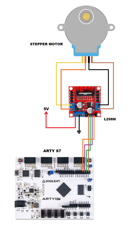
Now I show you the electrical diagram of the circuit that I assembled below.

Once our device is wired, we are ready for the programming of the Arty S7 board. We will see this matter in the next chapter.

Top Comments
-

robogary
-
Cancel
-
Vote Up
+1
Vote Down
-
-
Sign in to reply
-
More
-
Cancel
Comment-

robogary
-
Cancel
-
Vote Up
+1
Vote Down
-
-
Sign in to reply
-
More
-
Cancel
Children