element14 Community
element14 Community
    Register Log In
  • Site
  • Search
  • Log In Register
  • Community Hub
    Community Hub
    • What's New on element14
    • Feedback and Support
    • Benefits of Membership
    • Personal Blogs
    • Members Area
    • Achievement Levels
  • Learn
    Learn
    • Ask an Expert
    • eBooks
    • element14 presents
    • Learning Center
    • Tech Spotlight
    • STEM Academy
    • Webinars, Training and Events
    • Learning Groups
  • Technologies
    Technologies
    • 3D Printing
    • FPGA
    • Industrial Automation
    • Internet of Things
    • Power & Energy
    • Sensors
    • Technology Groups
  • Challenges & Projects
    Challenges & Projects
    • Design Challenges
    • element14 presents Projects
    • Project14
    • Arduino Projects
    • Raspberry Pi Projects
    • Project Groups
  • Products
    Products
    • Arduino
    • Avnet Boards Community
    • Dev Tools
    • Manufacturers
    • Multicomp Pro
    • Product Groups
    • Raspberry Pi
    • RoadTests & Reviews
  • Store
    Store
    • Visit Your Store
    • Choose another store...
      • Europe
      •  Austria (German)
      •  Belgium (Dutch, French)
      •  Bulgaria (Bulgarian)
      •  Czech Republic (Czech)
      •  Denmark (Danish)
      •  Estonia (Estonian)
      •  Finland (Finnish)
      •  France (French)
      •  Germany (German)
      •  Hungary (Hungarian)
      •  Ireland
      •  Israel
      •  Italy (Italian)
      •  Latvia (Latvian)
      •  
      •  Lithuania (Lithuanian)
      •  Netherlands (Dutch)
      •  Norway (Norwegian)
      •  Poland (Polish)
      •  Portugal (Portuguese)
      •  Romania (Romanian)
      •  Russia (Russian)
      •  Slovakia (Slovak)
      •  Slovenia (Slovenian)
      •  Spain (Spanish)
      •  Sweden (Swedish)
      •  Switzerland(German, French)
      •  Turkey (Turkish)
      •  United Kingdom
      • Asia Pacific
      •  Australia
      •  China
      •  Hong Kong
      •  India
      •  Korea (Korean)
      •  Malaysia
      •  New Zealand
      •  Philippines
      •  Singapore
      •  Taiwan
      •  Thailand (Thai)
      • Americas
      •  Brazil (Portuguese)
      •  Canada
      •  Mexico (Spanish)
      •  United States
      Can't find the country/region you're looking for? Visit our export site or find a local distributor.
  • Translate
  • Profile
  • Settings
FPGA
  • Technologies
  • More
FPGA
Blog XuLA2 FPGA - Up the Clock
  • Blog
  • Forum
  • Documents
  • Quiz
  • Events
  • Polls
  • Files
  • Members
  • Mentions
  • Sub-Groups
  • Tags
  • More
  • Cancel
  • New
Join FPGA to participate - click to join for free!
  • Share
  • More
  • Cancel
Group Actions
  • Group RSS
  • More
  • Cancel
Engagement
  • Author Author: Jan Cumps
  • Date Created: 4 Feb 2017 1:56 PM Date Created
  • Views 887 views
  • Likes 6 likes
  • Comments 2 comments
  • spartan_6
  • xilinx
  • fpga
  • xula2
  • vhdl
  • jcxula2
Related
Recommended

XuLA2 FPGA - Up the Clock

Jan Cumps
Jan Cumps
4 Feb 2017

The XuLA2 standard runs on a 12 MHz clock. That's plenty for many things, but not enough for some designs.

image

In my PWM with DeadBand  project, for instance, the effective signal frequency that the module outputs is halved for each bit of precision of the duty cycle register.

If you want to have 256 steps between 0 and 100% duty cycle, you need 8-bit precision and your maximum PWM output frequency is 47 kHz. When you need higher PWM frequency with the same duty cycle granularity, you can use a Digital Clock Manager to generate a (much!) faster clock signal for the PWM module.


I need a minimum 1 MHz output for the GaN half-bridge that I'm driving (an LMG5200). The deadband should be a in the range of 8 - 10 ns.

Let's assume that we allow for 2 ns steps (we can then set a deadband of 10 ns by skipping 5 ticks.

2ns means that our input frequency has to be 500 MHz. We can't do that - its beyond the capabilities of the Digital Clock Manager of the Spartan-6.

4ns is doable but a stretch. It'll require an up-sample to 250 MHz.


Only 12 MHz! Now what

That's the title of the Xess VHDL Tutorial chapter that covers this concept. Look there for the explanation.

I'll focus on a practical application.


library UNISIM;
use UNISIM.VComponents.all;
-- ...
architecture Behavioral of Rotary_Pwm is
-- ...
  signal clk_fast     : std_logic;
begin

   DCM_SP_inst : DCM_SP
   generic map (
      CLKFX_DIVIDE => 1,                     -- Divide value on CLKFX outputs - D - (1-32)
      CLKFX_MULTIPLY => 22                    -- Multiply value on CLKFX outputs - M - (2-32)
   )
   port map (
      CLKFX => clk_fast,    -- 1-bit output: Digital Frequency Synthesizer output (DFS)
      CLKIN => clk_i,       -- 1-bit input: Clock input
      RST => '0'            -- 1-bit input: Active high reset input
   );

  u0 : PwmDeadBand
    port map (
      clk_i => clk_fast,
  duty_i => accumulator_s,
  band_i => 64,
      pwmA_o => pwmA_o,
      pwmB_o => pwmB_o
      );
-- ...


The DCM_SP_inst is an instance of the Spartan-specific DCM_SP primitive. It's not a standard VHDL construct.

At this point, our design becomes device dependent. You can't just port it to another FPGA.


I've used the following design decisions:

To get the 4ns step rate the minimum frequency is 1/4ns = 250 MHz.

Our output frequency is going to be that frequency divided by 256, so we're just under our   MHz output goal.

We'll have to up it to at least 256 MHz.

With a 12 MHz clock as input, we'll need to multiply that clock with 22 and get 264 MHz.

Each step will have a period of 3.8 ns - close enough to the 4 ns we're aiming for.


We only have to pass that fast clock to the PWM module.

There's no reason to route it to the rotary encoder, it can keep running on the 12 MHz clacker.


image

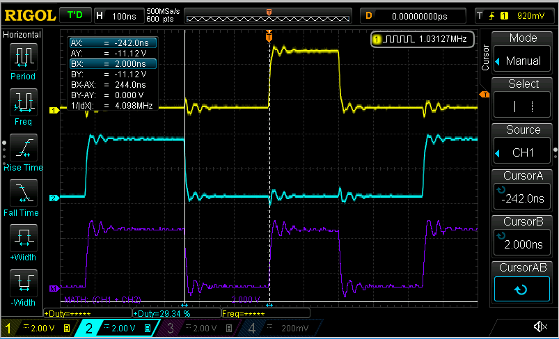
photo: Bart Simpson looks over a wall


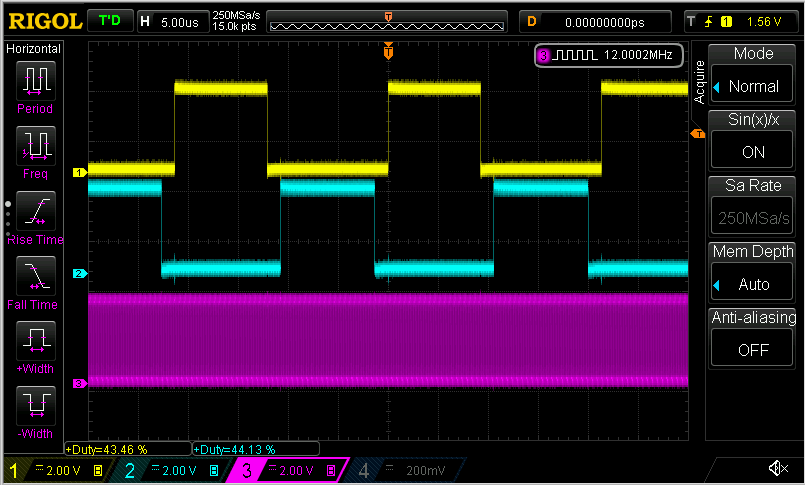
In the capture above, I've set a deadband of 64 clock ticks (to have something measurable on the scope).

The signal frequency is 1.03127 MHz (theoretical 12 MHz * 22 / 256 = 1.031250 MHz)

The time between the cursors is 244 ns for 64 dead band ticks. So the measured granularity of our deadband is 244ns / 64 = 3.8125 ns.


Here's a capture with 8 clock ticks.

image


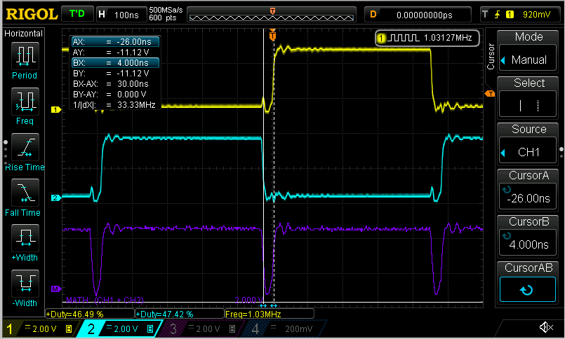
My GaN board will run with 2 or 3 ticks - I'd have to use different probe technique to show that.

Good captures in the neighbourhood of 8 ns (that's the deadband that I'll try to achieve) are hard on a 50 MHz scope


XuLA2 FPGA - First Impressions of the Development Tools
XuLA2 FPGA - SD Card Read and Write
XuLA2 FPGA - Rotary Encoder and VHDL
XuLA2 FPGA - PWM with Dead Band in VHDL
XuLA2 FPGA - Up the Clock
XuLA2 FPGA - Utility to Generate Pin Assignments
XuLA2 FPGA - Test the VGA StickIt! Module: Image Preparation
  • Sign in to reply

Top Comments

  • clem57
    clem57 over 8 years ago +1
    So the FPGA is capable, but not your scope, Nice project , That dead band is quite small!
  • Jan Cumps
    Jan Cumps over 8 years ago in reply to clem57

    C-3PO (Clem) wrote:


    ....

    That dead band is quite small!

    Yes, the GaN chip that I use switches at a high frequency, so the passive components can be small. To get a decent duty cycle the deadband (and propagation time consistency) has to be small too (and the device has to be able to stabilise in that short dead time).

    There's a nice "discrete component" way to generate the deadband. If you add that in front of the GaN chip you don't need the capability to generate it on the microcontroller or the fpga.

    You still need a PWM module that can achieve decent duty cycle resolution at 1 MHz though, but 8-10 ns isn't a strict requirement anymore then.

    • Cancel
    • Vote Up 0 Vote Down
    • Sign in to reply
    • More
    • Cancel
  • clem57
    clem57 over 8 years ago

    So the FPGA is capable, but not your scope, Nice projectimage, That dead band is quite small!image

    • Cancel
    • Vote Up +1 Vote Down
    • Sign in to reply
    • More
    • Cancel
element14 Community

element14 is the first online community specifically for engineers. Connect with your peers and get expert answers to your questions.

  • Members
  • Learn
  • Technologies
  • Challenges & Projects
  • Products
  • Store
  • About Us
  • Feedback & Support
  • FAQs
  • Terms of Use
  • Privacy Policy
  • Legal and Copyright Notices
  • Sitemap
  • Cookies

An Avnet Company © 2025 Premier Farnell Limited. All Rights Reserved.

Premier Farnell Ltd, registered in England and Wales (no 00876412), registered office: Farnell House, Forge Lane, Leeds LS12 2NE.

ICP 备案号 10220084.

Follow element14

  • X
  • Facebook
  • linkedin
  • YouTube