|
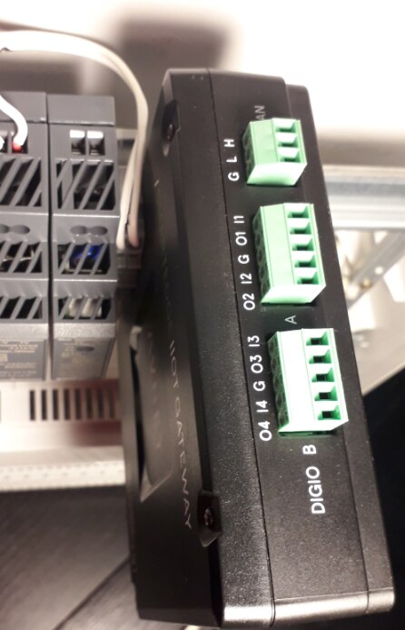
The SmartEdge IIOT GatewaySmartEdge IIOT Gateway is a Raspberry Pi 3 Compute based industrial Linux box. It runs Raspbian with some additions. There's a set of industrial hardware extensions. In this blog I review the isolated industrial I/O. |
GPIO Hardware
The SmartEdge IIOT Gateway (from now on: gateway) has two banks of isolated I/O - named DIGIO A and B.
All signals are isolated from the Raspberry part via optocouplers.
Each bank has 2 inputs and outputs that share a common ground*.
The input is high impedance and drives an optocoupler's input. The coupler's output is connected to a Raspberry GPIO pin.
The output is an open collector transistor, driven from a Raspberry GPIO pin via an optocoupler.
Bank A and B are isolated from each other.
Isolation is up to 2 kV.
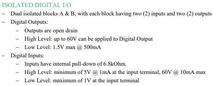
image: I/O specifications from the datasheet
The schematic shows the first input and output of bank A. Note that output is on the left, input on the right, and the external connector is shown in the middle.
The User Guide shows the full setup for both banks.
image: output and input of Bank A, I/O 1
While the Raspberry GPIO pins are I/O, the DIGIO pins are dedicated input or output.
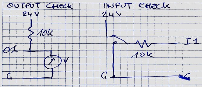
Here's an example test circuit for both input and output side.
image: simple output (left) and input test circuit
GPIO Firmware
Raspberry Pi users will be happy to see that the pins can be used just like the 3.3 V I/O pins.
They are supported by Linux character devices. You control and check their status by reading and writing to Linux files**.
This table shows the mapping between the DIGIO pins and the corresponding Linux devices.
| DIGIO | Linux device | Direction |
|---|---|---|
| A I1 | 200 | input |
| A O1 | 201 | output |
| A I2 | 202 | input |
| A O2 | 203 | output |
| B I1 | 204 | input |
| B O1 | 205 | output |
| B I2 | 206 | input |
| B O2 | 207 | output |
In this blog, I'm talking to the pins from Linux. There are plenty examples that show how to talk to Raspberry I/O from your favourite programming language.
Before you can use a pin, you have to export it.
# enable DIGIO A I1 and O1
echo 200 >/sys/class/gpio/export
echo 201 >/sys/class/gpio/export
The output pins have to be configured as outputs.
# make O1 an output pin
sudo echo out > /sys/class/gpio/gpio201/direction
You can drive an output by executing:
#switch O1
sudo echo 1 > /sys/class/gpio/gpio201/value
sudo echo 0 > /sys/class/gpio/gpio201/value
Checking an input pin's status is done like this:
#read I1
cat /sys/class/gpio/gpio201/value
As you can see, all is very similar to talking to the common Pi pins. But your lines can be up to 60 V.
When you want to use the typical Raspberry Pi GPIO pins, they are available too. The traditional Pi header is accessible inside the box.
* it's not really a ground but a shared reference point.
** they are indeed character devices. The Linux facing interface to set direction and work with the statuses seem to be files, e.g.: /sys/class/gpio/gpio201/value. In the background, there's a driver that translates that into hardware signals to the Broadcom chip.


Top Comments
-

Jan Cumps
-
Cancel
-
Vote Up
0
Vote Down
-
-
Sign in to reply
-
More
-
Cancel
Comment-

Jan Cumps
-
Cancel
-
Vote Up
0
Vote Down
-
-
Sign in to reply
-
More
-
Cancel
Children