element14 Community
element14 Community
    Register Log In
  • Site
  • Search
  • Log In Register
  • About Us
  • Community Hub
    Community Hub
    • What's New on element14
    • Feedback and Support
    • Benefits of Membership
    • Personal Blogs
    • Members Area
    • Achievement Levels
  • Learn
    Learn
    • Ask an Expert
    • eBooks
    • element14 presents
    • Learning Center
    • Tech Spotlight
    • STEM Academy
    • Webinars, Training and Events
    • Learning Groups
  • Technologies
    Technologies
    • 3D Printing
    • FPGA
    • Industrial Automation
    • Internet of Things
    • Power & Energy
    • Sensors
    • Technology Groups
  • Challenges & Projects
    Challenges & Projects
    • Design Challenges
    • element14 presents Projects
    • Project14
    • Arduino Projects
    • Raspberry Pi Projects
    • Project Groups
  • Products
    Products
    • Arduino
    • Avnet Boards Community
    • Dev Tools
    • Manufacturers
    • Multicomp Pro
    • Product Groups
    • Raspberry Pi
    • RoadTests & Reviews
  • Store
    Store
    • Visit Your Store
    • Choose another store...
      • Europe
      •  Austria (German)
      •  Belgium (Dutch, French)
      •  Bulgaria (Bulgarian)
      •  Czech Republic (Czech)
      •  Denmark (Danish)
      •  Estonia (Estonian)
      •  Finland (Finnish)
      •  France (French)
      •  Germany (German)
      •  Hungary (Hungarian)
      •  Ireland
      •  Israel
      •  Italy (Italian)
      •  Latvia (Latvian)
      •  
      •  Lithuania (Lithuanian)
      •  Netherlands (Dutch)
      •  Norway (Norwegian)
      •  Poland (Polish)
      •  Portugal (Portuguese)
      •  Romania (Romanian)
      •  Russia (Russian)
      •  Slovakia (Slovak)
      •  Slovenia (Slovenian)
      •  Spain (Spanish)
      •  Sweden (Swedish)
      •  Switzerland(German, French)
      •  Turkey (Turkish)
      •  United Kingdom
      • Asia Pacific
      •  Australia
      •  China
      •  Hong Kong
      •  India
      •  Korea (Korean)
      •  Malaysia
      •  New Zealand
      •  Philippines
      •  Singapore
      •  Taiwan
      •  Thailand (Thai)
      • Americas
      •  Brazil (Portuguese)
      •  Canada
      •  Mexico (Spanish)
      •  United States
      Can't find the country/region you're looking for? Visit our export site or find a local distributor.
  • Translate
  • Profile
  • Settings
1 Meter of Pi
  • Challenges & Projects
  • Design Challenges
  • 1 Meter of Pi
  • More
  • Cancel
1 Meter of Pi
Blog Gr0G - 09 - The control board
  • Blog
  • Forum
  • Documents
  • Polls
  • Files
  • Events
  • Mentions
  • Sub-Groups
  • Tags
  • More
  • Cancel
  • New
  • Share
  • More
  • Cancel
Group Actions
  • Group RSS
  • More
  • Cancel
Engagement
  • Author Author: amgalbu
  • Date Created: 12 Nov 2020 7:34 PM Date Created
  • Views 1448 views
  • Likes 3 likes
  • Comments 10 comments
  • 1meterofpi
  • gr0g
  • 1meter of pi
Related
Recommended

Gr0G - 09 - The control board

amgalbu
amgalbu
12 Nov 2020

Here is a list of the posts in this challenge

Gr0G - 01 - Introduction

Gr0G - 02 - Why aeroponics?

Gr0G - 03 - High-pressure system design

Gr0G - 04 - Mechanical design

Gr0G - 05 - Electrical design

Gr0G - 06 - Building the box

Gr0G - 07 - Playing with the Gertbot

Gr0G - 08 - Installing LEDs

Gr0G - 09 - The control board

Gr0G - 10 - Software design

Gr0G - 11 - Building the box (2)

Gr0G - 12 - Building the high-pressure system

Gr0G - 13 - Building the high-pressure system (2)

Gr0G - 14 - Piping

Gr0G - 15 - Improvements

Gr0G - 16 - Remote UI

Gr0G - 17 - Remote UI (2)

Gr0G - 18 - Conclusions


Source code available at https://github.com/ambrogio-galbusera/gr0g, https://github.com/ambrogio-galbusera/gr0g-ble-android and https://github.com/ambrogio-galbusera/gr0g-ble


Let's now start to build the control board. This is the electrical circuit we are going to build (it's a bit difficult to read, but the original Fritzing file is attached)

image

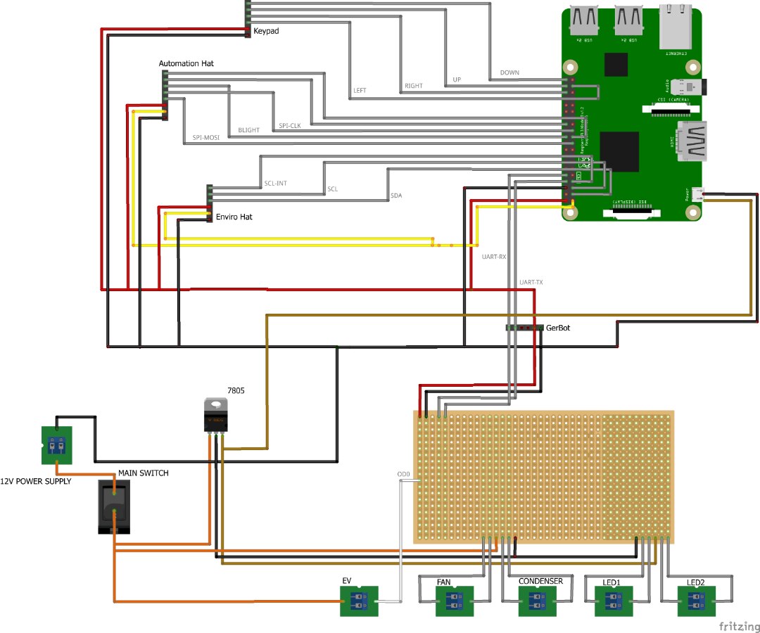
Some notes about this diagram

  • The control board takes a 12V dc power supply. It converts the 12V dc to 5V dc through a 7805. Since the output of a 7805 is not very "clean" (it has ripple and spikes that may cause damages to the Raspberry Pi and the other boards), I choose to connect the 7805 output to the USB connector of the Raspberry Pi. The USB connector has a Zener to eliminate spikes and some circuitry to level the ripple. Then the 5V and 3.3V to power up external boards is taken from the 40-pin header connector
  • Raspberry Pi absorbs a lot of current (up to 2A), so the 7805 is going to get very hot
  • The Keypad connector uses four GPIOs to read the status of keys to allow the user to navigate through the screens shown on the display of the PiMoroni Automation Hat. I could have connected the keypad to the PiMoroni Automation Hat inputs, but
    • PiMoroni Automation Hat has just three inputs (I need four inputs)
    • The library provided to control the PiMoroni Automation Hat tries to access the I2C bus as soon as you initialize the library itself, but I am going to use the sensors on the Enviro Hat
    • The PiMoroni Automation Hat inputs are connected directly to the Raspberry Pi GPIO pins

        For all these reasons, it's not so bad to connect keypad directly to the Raspberry Pi

  • The Automation Hat connector takes the SPI signals plus a GPIO (to control display backlight) and power supply (both 3.3V and 5V). The SPI bus is required to control the PiMoroni Automation Hat display. This display will be mounted on one of the vertical panels of the Gr0G box to show astronauts information about the status of the box
  • The Enviro Hat connector takes the I2C signals and power supply (both 3.3V and 5V). The I2C is required to access hat's sensors. The hat will be mounted on a bracket. The display on the EnviroHat will not be used
  • The Gertbot board requires an UART to be commanded and controlled. The power section will be connected to the 12V dc (for fan, condenser, and solenoid valve) and 5V (for LEDs)


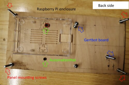
The Raspberry Pi, the Gertbot board, the PiMoroni Automation Hat will be mounted on a plywood board


imageimage

The boards have been then put in place. First, the Raspberry Pi

image

Then, the PiMoroni Hacker board with the connectors for the external boards

image

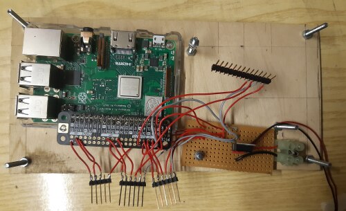
Finally, the Gertbot board

image

Then, the PiMoroni Automation Hat board has been installed on the front side of the plywood panel

image


UPDATE:

PWM output can not handle the current required by both the dehumidifier (fans + Peltier cell) and cooler. So I disconnected the Peltier cell from the PWM output pins and now I am going to switch on and off the cell itself by means of opendrain output 1. Since opendrain output are rated for 5A maximum (and the Peltier cell draws 6A) I used the opendrain output to drive a relay, and the relay NO pin will then be connected to the Peltier cell. The new diagram in shown in picture

image

  • Sign in to reply

Top Comments

  • balearicdynamics
    balearicdynamics over 4 years ago in reply to amgalbu +2
    Just FYI, if the board of Pimoroni is a real HAT – I mean, following the Pi HAT specifications – it should be identified by an EEPROM encoded in a specific way accessed by the I2C 0. This is just to make…
  • amgalbu
    amgalbu over 4 years ago in reply to balearicdynamics +2
    Yes Enrico I think it's possible to use two display by using two GPIOs as CSes for the two displays I didn't investigate this option but I think it's not too difficult but for sure this does not make possible…
  • dules
    dules over 4 years ago in reply to balearicdynamics +2
    You can check my solution for this problem here: Aquaponics Box: #2 - Hacking the HATs (both HATs from the challenger kit on single RPi)
Parents
  • skruglewicz
    skruglewicz over 4 years ago

    Hi amgalbu


    Nice design. Especially interested on how you are utilizing the hacker board. I couldn’t figure out how to implement it. Do you know if you can stack the hats? using the hacker?

    I was going to use two raspberry pi ‘s. Then I have to share my logic over the network. That would make the logic more complex.

    I’m new to all the circuit stuff. and I’m learning a real lot in this challenge  and having fun doing it. . It’s an excellent learning tool...

    I appreciate everyone helping me.

    Steve K

    • Cancel
    • Vote Up 0 Vote Down
    • Sign in to reply
    • More
    • Cancel
  • amgalbu
    amgalbu over 4 years ago in reply to skruglewicz

    Hello skruglewicz

    As far as I understand (I am not certain because pimoroni do not share the schematics of their products) you can not stack the hats.

    Looks like they use the same gpio as spi chip select signal so you can not drive two displays separately. This is why I used the pimoroni hacker board to wire just the signals I need. I really appreciated the labels etched on the hacker board: they are really helpful when you are soldering the wires. But I would have included the 40 pins female header inthe package...


    Cheers

    Ambrogio

    • Cancel
    • Vote Up +1 Vote Down
    • Sign in to reply
    • More
    • Cancel
  • skruglewicz
    skruglewicz over 4 years ago in reply to balearicdynamics

    good to know balearicdynamics

    • Cancel
    • Vote Up +1 Vote Down
    • Sign in to reply
    • More
    • Cancel
  • balearicdynamics
    balearicdynamics over 4 years ago in reply to amgalbu

    BTW, Ambrogio, as far as I know, the Pi has two SPI but a couple of displays I think can't be shared together depending on other details of the Pi architecture. At least not in a simple way. Instead, I think that one or more secondary Oled displays controlled by I2C are a feasible option.


    Enrico

    • Cancel
    • Vote Up +1 Vote Down
    • Sign in to reply
    • More
    • Cancel
  • amgalbu
    amgalbu over 4 years ago in reply to balearicdynamics

    Yes Enrico I think it's possible to use two display by using two GPIOs as CSes for the two displays

    I didn't investigate this option but I think it's not too difficult but for sure this does not make possible to stack Pimoroni hats

    • Cancel
    • Vote Up +2 Vote Down
    • Sign in to reply
    • More
    • Cancel
  • dules
    dules over 4 years ago in reply to balearicdynamics

    You can check my solution for this problem here:

    Aquaponics Box: #2 - Hacking the HATs (both HATs from the challenger kit on single RPi)

    • Cancel
    • Vote Up +2 Vote Down
    • Sign in to reply
    • More
    • Cancel
  • amgalbu
    amgalbu over 4 years ago in reply to dules

    Thank you dules

    I read your post and you did a great job!

    I expected it was possible but I didn't make further investigations because I just don't need the display on the Enviro Hat but, yes, your work can be of great help to all the challengers

    • Cancel
    • Vote Up +2 Vote Down
    • Sign in to reply
    • More
    • Cancel
Comment
  • amgalbu
    amgalbu over 4 years ago in reply to dules

    Thank you dules

    I read your post and you did a great job!

    I expected it was possible but I didn't make further investigations because I just don't need the display on the Enviro Hat but, yes, your work can be of great help to all the challengers

    • Cancel
    • Vote Up +2 Vote Down
    • Sign in to reply
    • More
    • Cancel
Children
No Data
element14 Community

element14 is the first online community specifically for engineers. Connect with your peers and get expert answers to your questions.

  • Members
  • Learn
  • Technologies
  • Challenges & Projects
  • Products
  • Store
  • About Us
  • Feedback & Support
  • FAQs
  • Terms of Use
  • Privacy Policy
  • Legal and Copyright Notices
  • Sitemap
  • Cookies

An Avnet Company © 2025 Premier Farnell Limited. All Rights Reserved.

Premier Farnell Ltd, registered in England and Wales (no 00876412), registered office: Farnell House, Forge Lane, Leeds LS12 2NE.

ICP 备案号 10220084.

Follow element14

  • X
  • Facebook
  • linkedin
  • YouTube