


Hi there! Following the previous post and the issues I found with the TFT and the RF24, I´m happy to share that I managed to solve it. Rather than solving it, I have had to apply the workaround briefly introduced earlier this week: add a master node to control the RF while delegating the rest of the functions to the slave one. Let´s go into the details after the project status.
Previous Posts
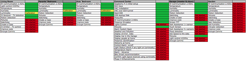
Project Status
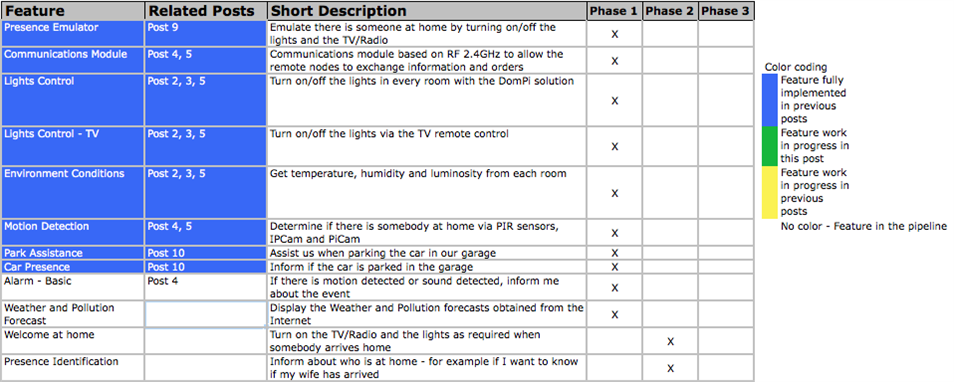
Architecture
Due to some incompatibilities of my TFT LCD with the SPI protocol - very probably it is not releasing the bus when the device is not addressed by the chip -, the RF24 board was not working properly. Both devices, the screen and the RF, are key components of the Garage node and hence, I could not sacrifice any. I have not found any potential solution rather than the work around to separate the TFT and the RF24, connecting them to two different Arduinos and interconnecting the Arduinos with I2C:
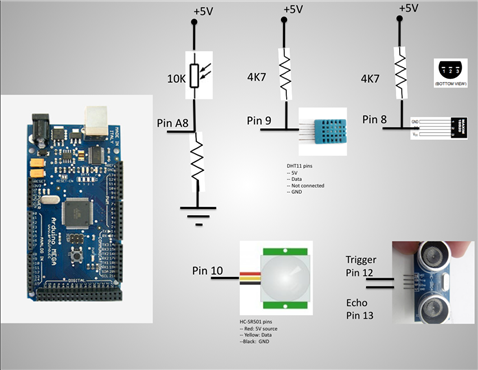
- Arduino Mega, Slave node: temperature, humidity, luminosity, movement, distance measurement, TFT display and I2C slave node
- Arduino Nano, Master node: 2.4Ghz radio frequency communications and I2C master node
| Slave node - sensor blocks | Garage node: master + slave + TFT + RF24 |
 |  |
I2C Implementation
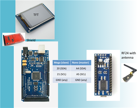
To enable the I2C comms between both Arduinos, the first step is to make sure that the Nano has the pins A4 and A5 soldered on it. You can see some notes on soldering the headers in PiIoT - DomPi 05: Ready for use Living Room and parents and kids´ bedrooms and the valid comments from ravi_butani about avoiding soldering on the breadboard. As a quick note, the A4 and A5 on the Nano are on the upper part, separated from the rest of the pins.
I2C implementation in the master
To add an I2C communication is fairly easy. From the HW perspective the only requirement is to connect the Nano pins A4 (SDA) and A5 (SCL) to the Mega pins 20 (SDA), 21 (SCL) respectively. Additionally and as a must in these architectures, you need to connect the GND of both Arduinos together, so that both share a common ground. You should not connect the 5V source together if you have two power supplies, one for each board. The reason is that they very probably will provide different voltage (f.e. 5.05V and 5.19V) and you would be short-circuiting them, which is bad and can destroy the power supplies...
From the SW perspective, I am using the Wire library from Arduino. This library includes nice examples (the Master writer and the Master reader) that have helped me to understand the protocol and leverage it in my Arduino sketches. Re the bit-rate, the I2C speed is not that high and can be increased by 4 by tweaking the Wire.h library. For the DomPi, the original speed is more than sufficient as both Arduinos will be just sharing few bytes per second the most. In any case, more information on increasing the bit rate in the I2C can be found here.
The protocol I have created is fairly simple. Via the "write_I2C_cmd" function below, the Master can ask the slave to send:
- all of the data: temperature, humidity, luminosity, motion and the distances of the three ultrasonic sensors. So far I am just using 1 sensor that I will install on the rear wall of the garage. However, implementing 3 will allow me grow easily - as a future development, I will install two more ultrasonic sensors to measure the distance with the walls on the left and on the right.
- confirm if the car is present. This request in return makes the slave to send all of the data as above, but for the distances, it calls another function (finetune) that calculates the distance more precisely by spending more time. This should not be required, but thought of really avoiding false positives.
After the master it has sent one of the above commands with the "write_I2C_cmd" function, it awaits the message from the slave with the function "requestI2C_data", see code below.
You can find later the whole code, but let me add here the I2C related code:
// Initialize I2C - in the loop function
Wire.begin();
...

void write_I2C_cmd(uint8_t cmd_slave, uint8_t info_slave) {
    Wire.beginTransmission(id_I2Cslave);    // transmit to device #8
    Wire.write(cmd_slave);                  // sends cmd byte
    Wire.write(info_slave);                 // sends info byte
    Wire.endTransmission();                 // stop transmitting
}

void requestI2C_data() {
  if (debug) Serial.println("Requesting I2C data...");
  Wire.requestFrom(8, 11);    //Request from I2C node 8 the data: 11 bytes
  if (debug) Serial.println("I2C after requestFrom...");
  uint8_t rxBytes=0;          //We count the number of bytes received, to ensure data is ok
  uint8_t buffer_rx[11];

  while (Wire.available()) {
    if (rxBytes<11) buffer_rx[rxBytes] = Wire.read();
    rxBytes++;
  }
  if (rxBytes!=11) {
    if (debug) {
      Serial.print("Error in I2C data transmission. Received bytes: ");
      Serial.println(rxBytes);
    }
  } else {
    t = 0;                    //reset global variable for the temperature
    t= (buffer_rx[0]<<8);     //First 2 bytes are for the temperature. First byte received is the most significant one, moving it to the highest 8 bits
    t += buffer_rx[1];       //Second byte: low byte of the temperature. No need to divde by 100, we wil just resend it via RF
    h = buffer_rx[2];
    l = buffer_rx[3];
    motionPIR = buffer_rx[4];
    dist_sensor1 = 0;         //reset global variable for the distance sensor 1 - same as with temperature
    dist_sensor1 = (buffer_rx[5]<<8);
    dist_sensor1 += buffer_rx[6];
    dist_sensor2=0;
    dist_sensor3=0;
    if (debug) {
      send_data_serial();
      uint8_t i;
      for (i=0;i<11;i++) {
        Serial.print(buffer_rx[i]);
        Serial.print("-");
      }
      Serial.println("");
    }
  }
}
I2C implementation in the slave
From the HW perspective, it is straightforward as well, and I used the pins 20 and 21 in the Mega as per above. From the SW perspective, the "protocol" I created waits for the Master to confirm which data it is expecting (if just the normal data or the data with the more accurate distance). This is done by the line and function Wire.onReceive(receive_I2C_data). Then the slave waits to be asked by the master when to send the data by the line and function Wire.onRequest(send_I2C_sensors_data)
  //Starting I2C communication with the Arduino master - in the loop function
  Wire.begin(id_I2Cslave);                          // join i2c bus with address #8
  Wire.onRequest(send_I2C_sensors_data);  // register I2C event, allows Master to request information - 11 bytes
  Wire.onReceive(receive_I2C_data);       // 2 bytes
...

void send_I2C_sensors_data() {
  // If we enter here, the I2C master has requested data to be sent.
  // Sends data to the Master. Master expects 11 bytes
  uint8_t buffer_tx[11]; //The wire.write function sends data per bytes
      //The function will send an array of data as follows:
      //    2xbytes for the int16_t of the temperature
      //    1xbyte for the humidity
      //    1xbyte for the light
      //    1xbyte for the motion
      //    2xbytes for the uint16_t of sensor distance 1
      //    2xbytes for the uint16_t of sensor distance 2
      //    2xbytes for the uint16_t of sensor distance 3

  tempo_watchdog.reiniciar_t0();    //Reinitialize the watchdog timer, since we have received an I2C message

  float t1 = t*100;             //multiplies by 100 to get rid of float and transmit only uint16
  int16_t t_tx = (int16_t) t1;
  uint16_t dist_cm_1_tx = 0;    //Initialize the variable, ensuring all bits are set to 0

  if (get_iscar) {
    //if get_iscar -> the master requested previously to send get_iscar data
    //the distance to tx will be the _iscar one
    get_iscar = false;
    dist_cm_1_tx = dist_cm_iscar;
  } else dist_cm_1_tx = dist_cm_1;

  buffer_tx[0] = t_tx >> 8;             //first byte of temperature uint16_t
  buffer_tx[1] = t_tx & 0xFF;           //second byte
  buffer_tx[2] = h;                     //humidity
  buffer_tx[3] = l;                     //luminosity
  buffer_tx[4] = is_motionPIR;          //motion
  buffer_tx[5] = dist_cm_1_tx >>8;      //first byte of distance sensor 1
  buffer_tx[6] = dist_cm_1_tx & 0xFF;   //second byte of distance sensor 1
  buffer_tx[7] = 0;                     //first byte of distance sensor 2
  buffer_tx[8] = 0;                     //second byte of distance sensor 2
  buffer_tx[9] = 0;                     //first byte of distance sensor 3
  buffer_tx[10] = 0;                    //second byte of distance sensor 3

  Wire.write(buffer_tx, 11); // respond with message with sensors data
  if (debug) {
    send_data_serial();
    uint8_t i;
    for (i=0;i<11;i++) {
      Serial.print(buffer_tx[i]);
    }
    Serial.println("");
  }
}


void receive_I2C_data(int rxBytes){
  //If we enter here is because the master has sent I2C message
  tempo_watchdog.reiniciar_t0();   //message received, it means there is communication
                                   // with the master, reinitiates the watchdog timer
  //We only expect 2 bytes: cmd and info
  if (rxBytes==2){
    cmd = Wire.read();
    info = Wire.read();
    if (debug) {
      Serial.print("Received I2C: cmd = ");
      Serial.print(cmd); Serial.print(" info = "); Serial.println(info);
    }
  } else {
    Serial.println("Unknown message received from I2C...");
    cmd = NO_ACTION;
    info = NO_ACTION;
  }
  switch (cmd) {
    case MODIFICAR_T_SLEEP: //Note translation: modificar = modify
      interval = info * 1000;
      //send ACK to I2C??
      break;
    case FORCE_SEND_MSG:
      force_send_msg = true;
      //send ACK to I2C??
      break;
    case GET_ISCAR_GARAGE:
      force_send_msg = true;
      get_iscar = true;
      //send ACK to I2C??
      dist_cm_iscar = getDistance_finetune(); //If asked to check if car is in garage,
                                      //we call the finetune function for better accuracy
      break;
    default:
      //Do nothing
      break;
  }
}
The protocol is quite simple and allows future growth if I need to implement more commands to the slave node. A mistake I made is mixing least significant byte with the most significant byte... The point is that when the slave was sending the 11 bytes, the master interpreted them in the reverse order, so the information shared was just wrong... I lost some hours to figure the error (checking sensors, debugging, print-outs, etc).
RF24 Module
To implement the RF24 I have just followed the same steps as in my post 4. Despite being straightforward, I did two mistakes. The first one is that I connecrted the base module of the RF24 to a 3.3V source instead of the 5V. It took me more than an hour to figure it out... The second one is that I prepared the sketch to test the RF by removing some previous code and hehe by mistake I removed the command to actually send any data... more time lost...
Regarding the radio range, I´m just in the limit and I plan to replace the current modules by new RF24 modules with an antenna. I have started to test it and looks better. So I will keep testing it and then just probably replace them.
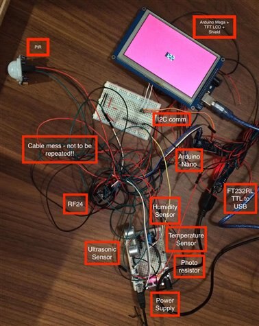
Summary of the Garage Node
In the end, the garage node has become a bit more complex than expected, but at least working. As you can see from the pictures below, the last minute changes have transformed two arduinos and some sensors into a mess of cables prone for errors and disconnections... I promise to arrange them much better! Will do it when I try to put them into a plastic box (like those you can by in the supermarkets to store your food) - as discussed in a forum discussion, I have not found any better enclosure for this node... 

Yet another issue that I have found was with the Serial.print and the Mega. In one of the lines I wanted to inform via the serial port of a warning like this "Bla, bla bla !!!". I also made some changes to the code and it stopped compiling. It did not compile regardless my efforts to change the additional code and so until I found in google that the Mega goes into monitoring status when the uploader sends a string with the "!!!" and the upload never takes place... more time lost...
You can find the Arduino codes for the master and slave parts of the Garage node below.
Arduino Master
#include <RF24Network.h>
#include <RF24.h>
#include <SPI.h>
#include <Wire.h>
#include <Defs_y_Clases.h>

/*
 * Code for the Slave node at the garage
 * It includes:
 *  RF 2.4Ghz communication with the master RF node
 *  I2C communications with the Arduino Slave
 *
*/

const bool debug = true;  //If true, enables debug dump via Serial port

// Radio with CE & CSN connected to pins 9 & 10
RF24 radio(9, 10);
RF24Network network(radio);

// Constants that identify this node and the node to send data to - RFwise
const uint16_t this_node = 5;
const uint16_t parent_node = 0;

//Constant for the id of the slave node on the I2C
const int id_I2Cslave = 8;

// Time between updates to the node (in ms)
unsigned long interval = 60000;  // every x/1000 sec
// The below objects are type Temporizador (timer). They replace the need of using the delay()
// This allows the script to run and do other tasks while waiting for the time to pass
Temporizador tempo_tx(interval, true);          //timer for the RF transmisions, every 60s it will force sending an update to the master node
Temporizador tempo_tx_maxdelay(900000, false);  //Maximum delay Id allow without having sent a message to the master node, 15 mins
Temporizador tempo_watchdog(3600000, false);    //Watchdog, if no update in 1h, activates watchdog

// Variables for the sensors
uint8_t h, l, motionPIR; //humidity and luminosity
int16_t t;   //temperature
uint16_t dist_sensor1=0, dist_sensor2=0, dist_sensor3=0;  //distance for ultrasound sensors 1,2,3

bool force_send_msg = false;  //Forces the transmission of the RF 2.4Ghz message to the node
bool get_iscar=false;

struct message_3 { // Structure of our message to send
  int16_t temperature;  //Temperature is sent as int16: I multiply by 100 the float value of the sensor and send it
                        //this way I avoid transmitting floats over RF
  uint8_t humidity;
  uint8_t light;
  uint8_t motion;
  uint16_t distance_sensor1;  //variable for the ultrasound sensor 1
  uint16_t distance_sensor2;  //variable for the ultrasound sensor 2
  uint16_t distance_sensor3;  //variable for the ultrasound sensor 3
};
message_3 message_tx;

struct message_action { // Structure of our message to receive
  unsigned char cmd;
  unsigned char info;
};
message_action message_rx;

RF24NetworkHeader header(parent_node); // The network header initialized for this node


void setup(void)
{
  if (debug) Serial.begin(9600);

  // Initialize all radio related modules
  SPI.begin();
  radio.begin();
  delay(50);
  radio.setPALevel(RF24_PA_HIGH);  //This can lead to issues as per https://arduino-info.wikispaces.com/Nrf24L01-2.4GHz-HowTo
                                  //use this radio.setPALevel(RF24_PA_LOW); if there are issues
  delay(50);
  radio.setChannel(108);          //Set channel over the WIFI channels
  delay(50);
  radio.setDataRate(RF24_250KBPS); //Decrease speed and improve range. Other values: RF24_1MBPS y RF24_2MBPS
  delay(50);
  network.begin(90, this_node);

  // Initialize I2C
  Wire.begin();

  if (debug) {
    Serial.print("Starting Master Node Garage. Node number: "); Serial.println(this_node);
  }
}

void loop() {
  // Update network data
  network.update();

  //Receive RF Data
  while (network.available()) {
    receive_data();
  }

  if (tempo_tx_maxdelay.is_Time()) {
    //If we enter here, means that tmax has already elapsed and we are to force data transmission
    force_send_msg = true;
  }

  if (get_iscar){
    //the RF main module requested to get_iscar
    get_iscar = false;
    force_send_msg = true;
    uint8_t cmd_slave = GET_ISCAR_GARAGE;         //Tell slave to get ISCAR, implies fine tune in the ultrasound
    uint8_t info_slave = 0;
    write_I2C_cmd(cmd_slave, info_slave); //We write into the I2C slave the cmd to get iscar
    delay(500);                           //We just requested get_iscar, allowing some time for the slave to respond
  }
  //Get and send the sensor data. This is done only if the timer is over or we force RF data
  if (tempo_tx.is_Time() || force_send_msg) {
    requestI2C_data();
    send_sensors_data();
    force_send_msg = false;
  }

  //force_send_msg = true;  //For testing purposes I can force the data to be sent
  //if (debug) Serial.println("Forcing send message every loop for tests.");
  delay(1000);  //Send data every 1000ms, maximum period, typically it will take longer
  check_watchdog();
}

void receive_data(){
  RF24NetworkHeader header;
  message_action message_rx;
  network.peek(header);
  if (header.type == '2') {
    tempo_watchdog.reiniciar_t0();   //message received, it means there is communication
                                     // with the master, reinitiates the watchdog timer
    network.read(header, &message_rx, sizeof(message_rx));
    if (debug) {
      Serial.print("Data received from node ");
      Serial.println(header.from_node);
    }
    // Check value and turn the LED on or off
    unsigned char cmd = message_rx.cmd;
    unsigned char info = message_rx.info;
    if (debug) {
      Serial.print("Command: "); Serial.println(cmd);
    }
    switch (cmd) {
      case MODIFICAR_T_SLEEP: //Note translation: modificar = modify
        interval = message_rx.info * 1000;
        send_cmd_per_RF(ACK, cmd);
        break;
      case FORCE_SEND_MSG:
        force_send_msg = true;
        send_cmd_per_RF(ACK, cmd);
        break;
      case GET_ISCAR_GARAGE:
        force_send_msg = true;
        get_iscar = true;
        send_cmd_per_RF(ACK, cmd);
        break;
      default:
        //Do nothing
        break;
    }

  } else {
    // This is not a type we recognize
    network.read(header, &message_rx, sizeof(message_rx));
    if (debug) Serial.print("Unknown message received from node ");
    if (debug) Serial.println(header.from_node);
  }
}

void write_I2C_cmd(uint8_t cmd_slave, uint8_t info_slave) {
    Wire.beginTransmission(id_I2Cslave);    // transmit to device #8
    Wire.write(cmd_slave);                  // sends cmd byte
    Wire.write(info_slave);                 // sends info byte
    Wire.endTransmission();                 // stop transmitting
}

void send_sensors_data(){
  header.type = '3'; // Header 3 for this node type of info
  // Only send values if any of them are different enough from the last time we sent:
  //  0.5 degree temp difference, 1% humdity or light difference, or different motion state

  if (abs(t - message_tx.temperature) > 30 || //sends data if there are significant changes in the sensors measurements
    abs(h - message_tx.humidity) > 1.0 ||
    abs(l - message_tx.light) > 5.0 ||
    force_send_msg) {   //Note: PIR change already covered in loop
      //set distance variables

      // Construct the message we'll send
      message_tx = (message_3){ t, h, l, motionPIR, dist_sensor1, dist_sensor2, dist_sensor3 };
      // Writing the message to the network means sending it
      if (network.write(header, &message_tx, sizeof(message_tx))) {
        //The RF transmission was successful
        tempo_tx.reiniciar_t0();            //Reinitialize the timers
        tempo_watchdog.reiniciar_t0();      //reinitiates the watchdog timer
        tempo_tx_maxdelay.reiniciar_t0();   //Reinitialize the timer for maxdelay
        if (debug) Serial.print("Message sent RF with data\n");
      } else {
        if (debug) Serial.print("Could not send message RF with data\n");
      }

      if (debug) {
        Serial.print("Temp_tx: "); Serial.print((message_tx.temperature)); Serial.print(" Temp_detected: "); Serial.println((t));
        Serial.print("Hum_tx: "); Serial.print(message_tx.humidity); Serial.print(" Hum_detected: "); Serial.println((h));
        Serial.print("Luminosity: "); Serial.print(message_tx.light); Serial.print(" Motion PIR: "); Serial.print(message_tx.motion);
        Serial.print(" Distance 1: "); Serial.println(message_tx.distance_sensor1);
      }
    }
}


void send_cmd_per_RF(unsigned char cmd, unsigned char info) {
  //Sends via RF the command and info
  //This is the way to update the master of the light status, ACK, etc
  header.type = '2';
  message_action message_x_RF;
  message_x_RF = (message_action){ cmd, info };

  // Writing the message to the network means sending it
  if (network.write(header, &message_x_RF, sizeof(message_x_RF))) {
    if (debug) Serial.print("Message sent RF\n");
    //There is communication with the master -> reinitiate the watchdog timer
    tempo_watchdog.reiniciar_t0();   //reinitiates the watchdog timer
  } else {
    if (debug) Serial.print("Could not send message RF\n");
  }

}

void check_watchdog() {
  //Controls the watchdog. Checks that there has been some communication with the
  //central node in the last 1h, either receiving a message from the center
  //or sending a message successfully to the center
  if (tempo_watchdog.is_Time()) {
    //At this point in time, this does nothing special, just print error via Serial
    //Improvement: to deactivate the automation and force lights to off, etc
    if (debug) Serial.println("Alarm! Watchdog timer. No successfull communication with the center");
    tempo_tx_maxdelay.reiniciar_t0();
  }
}

void requestI2C_data() {
  if (debug) Serial.println("Requesting I2C data...");
  Wire.requestFrom(8, 11);    //Request from I2C node 8 the data: 11 bytes
  if (debug) Serial.println("I2C after requestFrom...");
  uint8_t rxBytes=0;          //We count the number of bytes received, to ensure data is ok
  uint8_t buffer_rx[11];

  while (Wire.available()) {
    if (rxBytes<11) buffer_rx[rxBytes] = Wire.read();
    rxBytes++;
  }
  if (rxBytes!=11) {
    if (debug) {
      Serial.print("Error in I2C data transmission. Received bytes: ");
      Serial.println(rxBytes);
    }
  } else {
    t = 0;                    //reset global variable for the temperature
    t= (buffer_rx[0]<<8);     //First 2 bytes are for the temperature. First byte received is the most significant one, moving it to the highest 8 bits
    t += buffer_rx[1];       //Second byte: low byte of the temperature. No need to divde by 100, we wil just resend it via RF
    h = buffer_rx[2];
    l = buffer_rx[3];
    motionPIR = buffer_rx[4];
    dist_sensor1 = 0;         //reset global variable for the distance sensor 1 - same as with temperature
    dist_sensor1 = (buffer_rx[5]<<8);
    dist_sensor1 += buffer_rx[6];
    dist_sensor2=0;
    dist_sensor3=0;
    if (debug) {
      send_data_serial();
      uint8_t i;
      for (i=0;i<11;i++) {
        Serial.print(buffer_rx[i]);
        Serial.print("-");
      }
      Serial.println("");
    }
  }
}

void send_data_serial() {
  if (debug) {
    Serial.print("Temp_detected: "); Serial.println((t));
    Serial.print("Hum_detected: "); Serial.println((h));
    Serial.print("Luminosity: "); Serial.println(l);
    Serial.print("Motion PIR: "); Serial.println(motionPIR);
    Serial.print("Distance 1: "); Serial.println(dist_sensor1);
    Serial.print("Received I2C packet from slave: ");
  }
}
Arduino Slave
#include <Wire.h>
#include <OneWire.h>
#include <DallasTemperature.h>
#include <DHT.h>
#include <UTFT.h>
//#include <UTouch.h>
//#include <UTFT_Buttons.h>
#include <NewPing.h>
#include <Defs_y_Clases.h>

/*
 * Code for the Slave Node at the garage
 * It includes:
 *  Temperature sensor
 *  Humidity sensor
 *  Luminosity sensor
 *      -----   Removed due to SPI incompatibility ----- RF card at 2.4GHz
 *  PIR motion detector
 *  TFT Screen 5 inches
 *  I2C communications with Arduino master
 *
 */

const bool debug = false;  //If true, enables debug dump via Serial port
// One wire pin - Temperature sensor
#define ONE_WIRE_BUS 8

// The DHT humidity sensor pin
#define DHTPIN 9
#define DHTTYPE DHT11

#define PIR_PIN_GARAGE  10
#define TRIGGER_PIN     12  // Arduino pin tied to trigger pin on the ultrasonic sensor.
#define ECHO_PIN        13  // Arduino pin tied to echo pin on the ultrasonic sensor.
#define MAX_DISTANCE    500 // Maximum distance we want to ping for (in centimeters). Maximum sensor distance is rated at 400-500cm.
#define COLOR_VERDE     VGA_LIME
#define COLOR_ROJO      VGA_RED
#define COLOR_AMARILLO  VGA_YELLOW
#define COLOR_AMBAR     255,127,0
#define COLOR_AZUL      VGA_BLUE

// Initialize display
UTFT myGLCD(TFT01_50,38,39,40,41);          //For the 5 inch screen //UTFT    myGLCD(TFT01_24_8,19,18,17,16);   //For the 2.4 inches

// Initialize touchscreen
//UTouch  myTouch( 15, 8, 14, 9, 8);
// Initialize Buttons
//UTFT_Buttons  myButtons(&myGLCD, &myTouch);

// Declare which fonts we will be using
extern uint8_t SevenSegNumFont[];
//extern uint8_t BigFont[];
//extern uint8_t SmallFont[];

NewPing sonar(TRIGGER_PIN, ECHO_PIN, MAX_DISTANCE); // NewPing setup of pins and maximum distance.
Temporizador tempo_ultrasonido(50, false);  //Allows at min 50ms before restarting the ultrasound sensor
Temporizador tempo_motion(120000, false);   //If no movement in 120s, it turns off the LCD screen
uint16_t dist_cm_1=0, prev_dist_cm_1, v=0;
uint16_t dist_cm_iscar=0;
unsigned long prev_t=0;
int Xpos, Ypos;                             //LCD position to display the distance in the display
bool is_actDisplay = false;                 //States if we need to update the display. Variable gets reset
                                            //if there was movement in the last 120s
bool prev_PIR_status = false;               //Stores previous status of the PIR, for debug purposes only

//Humidity sensor DHT object
DHT dht(DHTPIN, DHTTYPE);

// Setup a oneWire instance to communicate with any OneWire devices
OneWire oneWire(ONE_WIRE_BUS);
DallasTemperature sensors(&oneWire); // Pass our oneWire reference to Dallas Temperature.
//NOTE: in line below I need to modify the address if I use a different temp sensor
DeviceAddress insideThermometer = {0x28, 0xFF, 0xAB, 0x9D, 0x54, 0x15, 0x03, 0x63};
//Temp address of the sensor: 28FFAB9D54150363

// Photocell variable
byte photocellPin = A8;

uint8_t cmd=0, info=0;    //Variables to store I2C message sent by the Master

// Timers
unsigned long interval = 60000;  // rep milisecs to activate the itmers with
// The below objects are type Temporizador (timer). They replace the need of using the delay()
// This allows the script to run and do other tasks while waiting for the time to pass
Temporizador tempo_tx(interval, true);          //timer for the sensors reading, every 60s it will force reading
Temporizador tempo_watchdog(3600000, false);    //Watchdog, if no update in 1h, activates watchdog

// Variables for the sensors
float h, t; //humidity and temperature
int l; //luminosity
bool is_motionPIR = false;    //Stores current status of the PIR motion sensor
bool is_motionPIR_prev=false; //Stores prev status of the PIR motion sensor,
                              //if different than current, then forces to send a message:new movement detected
bool force_send_msg = false;  //Forces the transmission of the RF 2.4Ghz message to the node
bool get_iscar = false;       //Not yet fully implemented

//Constant for the id of this slave node on the I2C
const int id_I2Cslave = 8;

void setup(void)
{
  if (debug) Serial.begin(9600);

  //Starting I2C communication with the Arduino master
  Wire.begin(id_I2Cslave);                          // join i2c bus with address #8
  Wire.onRequest(send_I2C_sensors_data);  // register I2C event, allows Master to request information - 11 bytes
  Wire.onReceive(receive_I2C_data);       // 2 bytes

  // Initialize the DHT library
  dht.begin();

  //Initialize pins
  pinMode(TRIGGER_PIN, OUTPUT);     //Ultrasound sensor
  pinMode(ECHO_PIN, INPUT);         //Ultrasound sensor
  pinMode(PIR_PIN_GARAGE, INPUT);   //PIR sensor

  // Initial setup LCD
  myGLCD.InitLCD();
  myGLCD.setFont(SevenSegNumFont);
  //myTouch.InitTouch();
  //myTouch.setPrecision(PREC_MEDIUM);
  //myGLCD.setFont(SmallFont);
  //myGLCD.setBackColor(0, 0, 255);
  //myGLCD.setBackColor(COLOR_AZUL);
  //myButtons.setTextFont(BigFont);
  //myButtons.setTextFont(SmallFont);
  Xpos = myGLCD.getDisplayXSize()/2 - 50;
  Ypos = myGLCD.getDisplayYSize()/2 - 16;

  //Get oneWire devices on bus
  sensors.begin();
  sensors.setResolution(insideThermometer, 12);

  //Initial distance of the ultrasound
  dist_cm_1 = getDistance_finetune();
  v = getSpeed(dist_cm_1);      //Not yet fully implemented

  delay(1000);                  //Allows some sensor to set up: PIR, DHT, etc
  myGLCD.fillScr(COLOR_AZUL);

  if (debug) {
    Serial.println("Starting Garage Node TFT Screen 5 inches, slave node.");
    Serial.print("Ultrasound Echo pin: "); Serial.println(ECHO_PIN);
    Serial.print("Ultrasound Trigger pin: "); Serial.println(TRIGGER_PIN);
    Serial.print("PIR Sensor pin: "); Serial.println(PIR_PIN_GARAGE);
    Serial.print("Dallas Temperature sensor: "); Serial.println(ONE_WIRE_BUS);
    Serial.print("DHT humidity sensor: "); Serial.println(DHTPIN);
  }
}

void loop() {
  if (change_inPIRsensor()){
    //If there is change in PIR, forces sensors reading
    force_send_msg = true;
  }
  //Check if it is time to read sensors data
  if (tempo_tx.is_Time() || force_send_msg) {
    force_send_msg = false;
    read_sensors_data();
  }

  reportDistance(); //if appropriate, reports the Distance from ultrasound to the TFT screen
  check_watchdog();

  if (debug) send_data_serial();
}

void receive_I2C_data(int rxBytes){
  //If we enter here is because the master has sent I2C message
  tempo_watchdog.reiniciar_t0();   //message received, it means there is communication
                                   // with the master, reinitiates the watchdog timer
  //We only expect 2 bytes: cmd and info
  if (rxBytes==2){
    cmd = Wire.read();
    info = Wire.read();
    if (debug) {
      Serial.print("Received I2C: cmd = ");
      Serial.print(cmd); Serial.print(" info = "); Serial.println(info);
    }
  } else {
    Serial.println("Unknown message received from I2C...");
    cmd = NO_ACTION;
    info = NO_ACTION;
  }
  switch (cmd) {
    case MODIFICAR_T_SLEEP: //Note translation: modificar = modify
      interval = info * 1000;
      //send ACK to I2C??
      break;
    case FORCE_SEND_MSG:
      force_send_msg = true;
      //send ACK to I2C??
      break;
    case GET_ISCAR_GARAGE:
      force_send_msg = true;
      get_iscar = true;
      //send ACK to I2C??
      dist_cm_iscar = getDistance_finetune(); //If asked to check if car is in garage,
                                      //we call the finetune function for better accuracy
      break;
    default:
      //Do nothing
      break;
  }
}

void read_sensors_data() {
  sensors.requestTemperatures();
  h = dht.readHumidity();
  t = sensors.getTempC(insideThermometer);
  //Sensor for PIR is read separately. No need to re-read it here
  //Sensor for distance (ultrasound) is read separately. No need to re-read it here
  // Read photocell and constrains data within a range and then maps it to range 0% - 100%
  l = analogRead(photocellPin);
  l = constrain(l, 70, 850);
  l = map(l, 70, 850, 100, 0);
}

void reportDistance() {
  //If there was movement or the display is active, it gets the distance and reports it via TFT screen
  //Once there is no movement detected, waits 2 mins and turns off screen if no movement
  bool motion_detected = is_motion();
  if (motion_detected || is_actDisplay) {
    //if movement or is_actDisplay, we update the TFT display
    dist_cm_1 = getDistance();
    //v = getSpeed(dist_cm_1);
    displayDistance(dist_cm_1, true);
    //displaySpeed(v);
    if (motion_detected) {
      tempo_motion.reiniciar_t0();   //it reinitialize the timer only if there was movement
      is_actDisplay = true;
    }
  }
  if (tempo_motion.is_Time()){
    //If 2 mins have gone without PIR movement, we turn off the display
    is_actDisplay = false;
    displayDistance(0, false);
  }
}

bool is_motion() {
  //returns value of the PIR sensor, which directly implies or not movement
  bool b = (digitalRead(PIR_PIN_GARAGE)==HIGH);
  if (debug) {
    //For debug purposes, we notify of changes on the PIR status
    if (b && !prev_PIR_status) {
      //Motion detected and there was no motion before,
      //hence inform via Serial and update variable
      Serial.println("PIR: Motion started");
      prev_PIR_status = true;
    } else if (!b && prev_PIR_status) {
      //There is no motion detected and there was motion before,
      //we inform not it stopped and update variable
      Serial.println("PIR: Motion stopped");
      prev_PIR_status = false;
    }
  }
  if (debug) {
    Serial.print("PIR Motion status:");
    Serial.print(b); delay(500);
  }
  return b;
}

bool change_inPIRsensor() {
  //True if there is a change in the PIR sensor: LOW to HIGH or HIGH to LOW
  bool b;
  is_motionPIR = (digitalRead(PIR_PIN_GARAGE)==HIGH);  //updates current state of the PIR
  b = (is_motionPIR!=is_motionPIR_prev);            //if current != previous state -> change
  is_motionPIR_prev = is_motionPIR;
  return b;
}

unsigned int getDistance_finetune() {
  //we called, gets the ultrasound distnace, but tries to get more accurate measurements
  //this function is mainly uses for the feature: is the car in the garage
  //for this feature we dont need much speed but yes high accuracy to avoid false positives
  unsigned int meassure[7]={0,0,0,0,0,0,0};         //Variable to contain array of distances
  unsigned int max_val=0, min_val=MAX_DISTANCE * 2; //Variables to store max and min values
  unsigned int val=0;                               //Value to return
  int i;
  //We will make the 7 measurements, and then remove the max and min values and perform an average
  for (i=0;i<7;i++) {
    meassure[i] = getDistance();
    val += meassure[i];                               //We add all of the meassurements
    if (max_val < meassure[i]) max_val = meassure[i]; //store max value
    if (min_val > meassure[i]) min_val = meassure[i]; //store min value
  }
  //To remove the max and min, we just substract them from the sum
  val = val - max_val - min_val;
  //Now we just take the average by dividing by 5
  val = val / 5;
  if (debug) {
    Serial.print("Valor medio de Val para fine tune: ");
    Serial.println(val);
  }
  return val;
}

unsigned int getDistance() {
  //gets the ultrasound distance, it will obtain a median of the measuremnts
  //this function is mainly used for park assistance: we dont want to delay too much
  //the display refresh, hence not much finetuning in the value
  while (!tempo_ultrasonido.is_Time() ) {
    //Allow 50ms before next ultrasound check, to ensure no false echos come in
  }
  //unsigned int uS = sonar.ping(); // Send ping, get ping time in microseconds (uS).
  unsigned int uS = sonar.ping_median(); // Send ping, get ping time in microseconds (uS).
  return (sonar.convert_cm(uS)); // Convert ping time to distance and print result (0 = outside set distance range, no ping echo)
}

void displayDistance(uint16_t dist_cm_1a, bool showDist){
  //display distance in screen, if showDist=false clears screen
  if (showDist) {
    if (debug) Serial.print("Dist: ");
    if (debug) Serial.print(dist_cm_1a);
    if (debug) Serial.println (" cm");
    //myGLCD.lcdOn();
    if (dist_cm_1a > 200) myGLCD.fillScr(COLOR_VERDE);
    else if (dist_cm_1a > 20) myGLCD.fillScr(COLOR_AMARILLO);
    else myGLCD.fillScr(COLOR_ROJO);
    String s = String(dist_cm_1a);
    if (dist_cm_1a < 100) s = "0"+s;  //If 2 digits, adds 0s to the left
    if (dist_cm_1a <  10) s = "0"+s;
    myGLCD.print(s, Xpos, Ypos);  //If 1 digit, adds 0 to the left
  } else {
    //we just clear screen and turn it off
    myGLCD.clrScr();
    if (debug) Serial.println ("No activity. Screen to off");
    //myGLCD.lcdOff();
  }
}

unsigned int getSpeed(unsigned int dist_cm_1a){
  unsigned int v1=0;

  unsigned long t1 = (micros() - prev_t)/1000;  //Calculo incremento de t
  unsigned long dist = abs(dist_cm_1a - prev_dist_cm_1)*1000; //Calculo incremento de distancia
  v1 = (unsigned int) dist/t1;
  prev_dist_cm_1 = dist_cm_1a; //reinicio distancia inicial
  prev_t = micros(); //reinicio t0
  return v1;
}

void displaySpeed(unsigned int v1) {
  if (debug) Serial.print("Velo: ");
  if (debug) Serial.print(v1);
  if (debug) Serial.println (" cm/s");
}

void check_watchdog() {
  //Controls the watchdog. Checks that there has been some communication with the
  //central node in the last 1h, either receiving a message from the center
  //or sending a message successfully to the center
  if (tempo_watchdog.is_Time()) {
    //To be implemented
    //At this point in time, this does nothing special, just print error via Serial
    //Improvement: to ensure lights to off, etc
    if (debug) Serial.println("Alarm! Watchdog timer. No successfull communication with the center");
  }
}

void send_data_serial() {
  if (debug) {
    Serial.print("Temp_detected: "); Serial.println((t));
    Serial.print("Hum_detected: "); Serial.println((h));
    Serial.print("Luminosity: "); Serial.println(l);
    Serial.print("Motion PIR: "); Serial.println(is_motionPIR);
    Serial.print("Distance 1: "); Serial.println(dist_cm_1);
    Serial.print("Sending I2C to master: ");
  }
}

void send_I2C_sensors_data() {
  // If we enter here, the I2C master has requested data to be sent.
  // Sends data to the Master. Master expects 11 bytes
  uint8_t buffer_tx[11]; //The wire.write function sends data per bytes
      //The function will send an array of data as follows:
      //    2xbytes for the int16_t of the temperature
      //    1xbyte for the humidity
      //    1xbyte for the light
      //    1xbyte for the motion
      //    2xbytes for the uint16_t of sensor distance 1
      //    2xbytes for the uint16_t of sensor distance 2
      //    2xbytes for the uint16_t of sensor distance 3

  tempo_watchdog.reiniciar_t0();    //Reinitialize the watchdog timer, since we have received an I2C message

  float t1 = t*100;             //multiplies by 100 to get rid of float and transmit only uint16
  int16_t t_tx = (int16_t) t1;
  uint16_t dist_cm_1_tx = 0;    //Initialize the variable, ensuring all bits are set to 0

  if (get_iscar) {
    //if get_iscar -> the master requested previously to send get_iscar data
    //the distance to tx will be the _iscar one
    get_iscar = false;
    dist_cm_1_tx = dist_cm_iscar;
  } else dist_cm_1_tx = dist_cm_1;

  buffer_tx[0] = t_tx >> 8;             //first byte of temperature uint16_t
  buffer_tx[1] = t_tx & 0xFF;           //second byte
  buffer_tx[2] = h;                     //humidity
  buffer_tx[3] = l;                     //luminosity
  buffer_tx[4] = is_motionPIR;          //motion
  buffer_tx[5] = dist_cm_1_tx >>8;      //first byte of distance sensor 1
  buffer_tx[6] = dist_cm_1_tx & 0xFF;   //second byte of distance sensor 1
  buffer_tx[7] = 0;                     //first byte of distance sensor 2
  buffer_tx[8] = 0;                     //second byte of distance sensor 2
  buffer_tx[9] = 0;                     //first byte of distance sensor 3
  buffer_tx[10] = 0;                    //second byte of distance sensor 3

  Wire.write(buffer_tx, 11); // respond with message with sensors data
  if (debug) {
    send_data_serial();
    uint8_t i;
    for (i=0;i<11;i++) {
      Serial.print(buffer_tx[i]);
    }
    Serial.println("");
  }
}
Nodes´ Dashboard
Top Comments
-

clem57
-
Cancel
-
Vote Up
+1
Vote Down
-
-
Sign in to reply
-
More
-
Cancel
-

mg.sergio
in reply to clem57
-
Cancel
-
Vote Up
0
Vote Down
-
-
Sign in to reply
-
More
-
Cancel
Comment-

mg.sergio
in reply to clem57
-
Cancel
-
Vote Up
0
Vote Down
-
-
Sign in to reply
-
More
-
Cancel
Children