Congratulations to robogary for Spooky Mailbox Skullies: Dusk to Dawn & dual PIR ->555 , Enables the Spook! You are the grand prize winner and you win a $200 shopping cart.
Congratulations to dougw for Jumbo Blue 555, rsjawale24 for How to use 555 timer IC for sensor interfacing , and wolfgangfriedrich for Ludicrous 555! You are the first place winners and a $100 shopping cart.
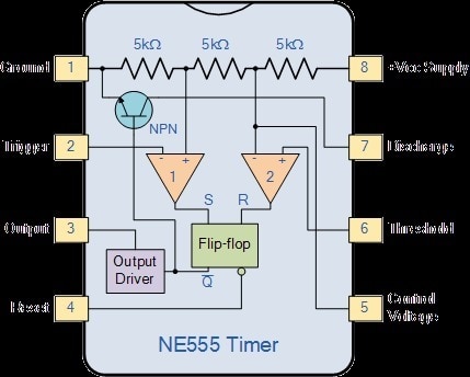
Like Arduino, 555 Timers are something people just love so in honor of the 50th anniversary of the release of the first 555 Timer, we are launched a 555 Timer Madness contest. The challenge was to do something special or unusual using 555 timers. The 555 timer is very versatile and it can be used in a variety of circuits and in unusual circuits such as a Schmidt triggers, abstable gadgets, long period timers, LED flashers and alarms, signal injectors, egg timers, continuity timers, morse code timers, beeping prank devices, security trip alarms, music synthesizers, traffic light control systems, and more.
The winning projects speak from themselves, but we got a lot really great blogs and projects related to 555 Timers. This contest was a highlight of the year for Project14 program. It was also really great to see so many new people posting multiple blogs on 555 Timers on the community. We would like to give a shout out to the following members and their first projects on the community. flyingbeanfor NE555: Ring counter, Color Chase, copper wires; AE7HD for 555 timer Remote Capacitance Sensor - fluid level, body detector, touch sensor, Dual TLC555 Capacitance Meter 0.1pF Resolution, Pulse Reverse Electroplating/Electroetching Using 555 Timers, and Class D Amplifier TLC555 Timer Based PWM Audio Amp; JWx for Lead battery regenerator using 555 and Dawn detector with hysteresis using 555; and davy with Electronic Mosquito Repellent Circuit. We want to encourage you to participate in more contests so if you message me tariq.ahmad with an address to send it to I will send you some free swag from the element14 community!
Special thanks to our community judges: DAB , baldengineer, and genebren!
Without further ado here are your winners...
Grand Prize Winner:
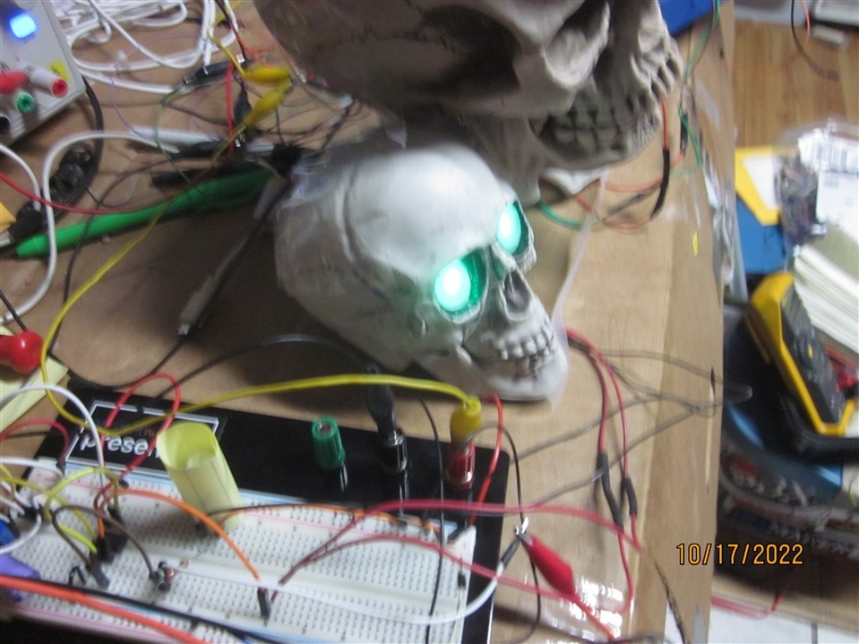
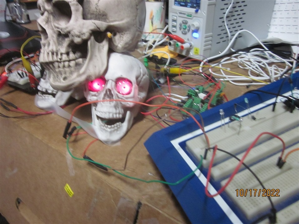
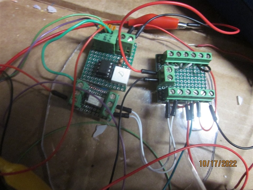
Spooky Mailbox Skullies: Dusk to Dawn & dual PIR ->555 , Enables the Spook by robogary
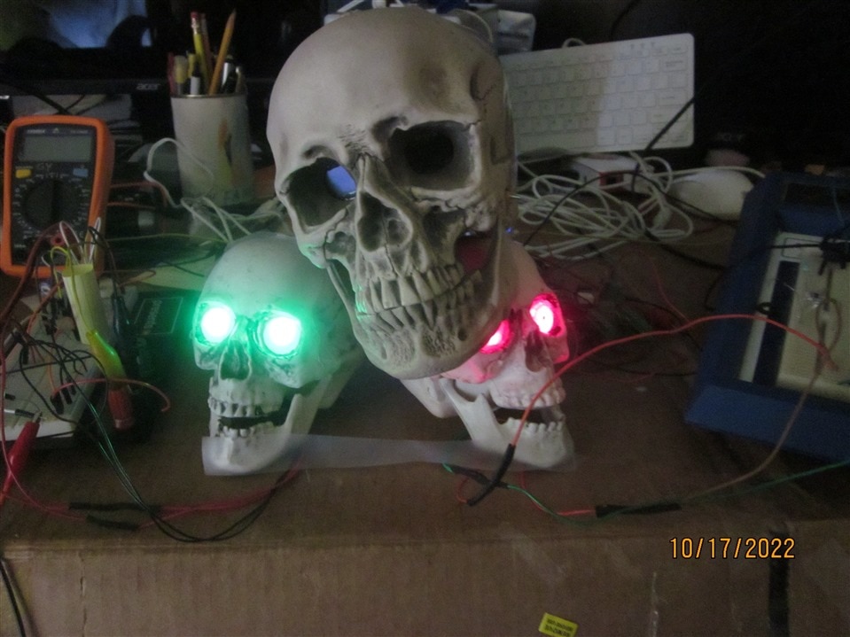
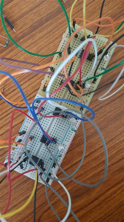
What do you get with a photo resistor, qty 3 555 timer ICs, qty 2 SR-HC505 PIRs, and 3 of your favorite skully friends? A SPOOKY SCARE AT THE MAILBOX awaits your neighbors and postman. Whats unique? Each PIR output is wired direct to a 555 timer IC RESET input.
| {gallery}My Gallery Title |
|---|
|
|
|
|
|
|
|
|
First Place Winners:
Jumbo Blue 555 by dougw
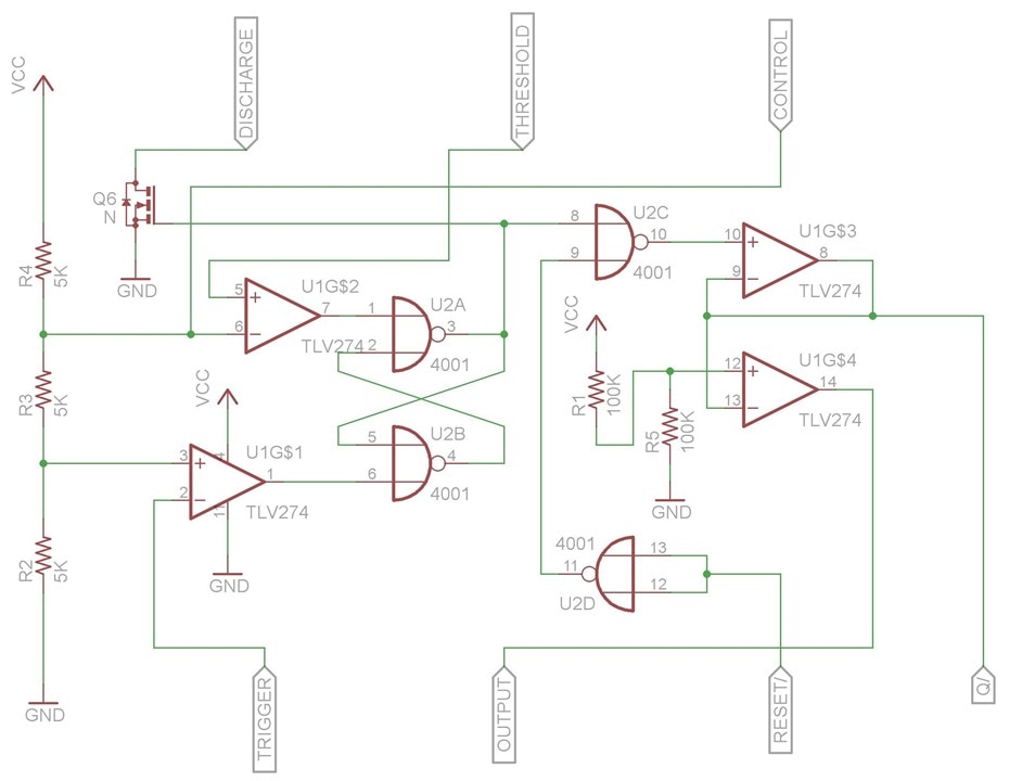
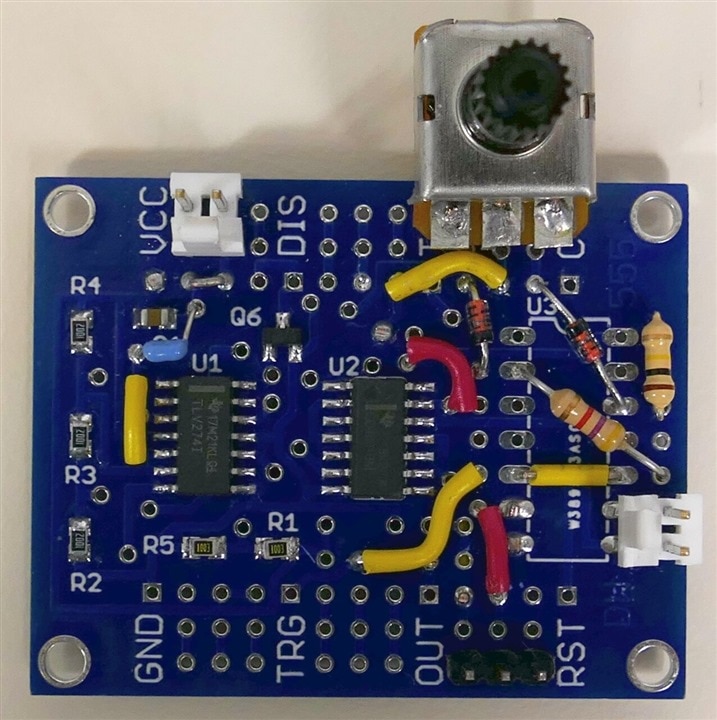
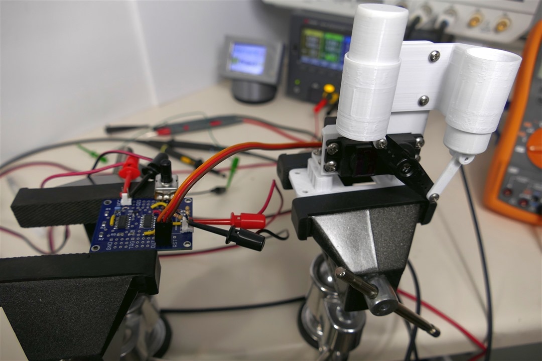
This project started with designing a discrete bipolar transistor design that directly implements the internal circuitry of a classic NE555. After capturing the schematic dougw noticed other people had already built such projects, so he redesigned the circuit to implement the CMOS variant of 555 using MOSFETS. He ended up with 26 MOSFETS in the circuit and it looked like the output stage would have some shoot-through, so he decided to try and implement a close functional equivalent of what a 555 circuit does. This ended up needing just 2 chips ( a quad op-amp chip and a quad NOR gate chip) plus one FET. Since he was designing it onto a PCB, he figured he would provide some breadboard space to add the typical components found around 555 circuit applications. This would allow 555 circuits to be explored all the way from internal functional activity to complete circuit modules like oscillators. The circuit boards are blue, so this project is called the Jumbo Blue 555.
| {gallery}My Gallery Title |
|---|
|
|
|
|
|
|
|
|
How to use 555 timer IC for sensor interfacing by rsjawale24
-
How to use 555 timer IC for sensor interfacing: Converting the sensor output to frequency
-
How to use 555 timer IC for sensor interfacing: Part-2 Wireless transmission
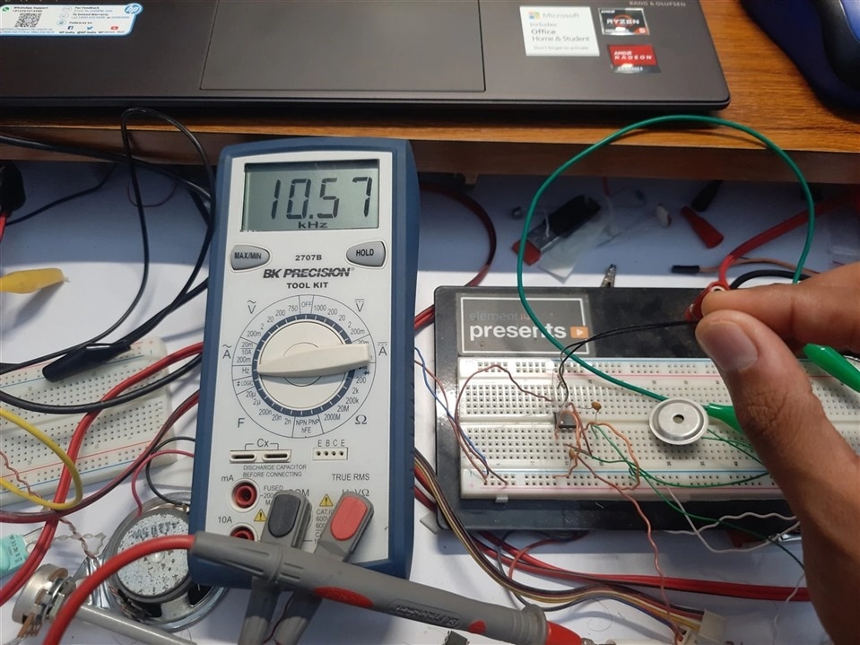
While experimenting with the thermistors, rsjawale24 wanted to transmit the thermistor's temperature reading (change is resistance) over a long distance using some wireless technology. However, since the thermistor circuits use a voltage divider to read the DC voltage change due to the change in its resistance with respect to the temperature, this DC output cannot be transmitted wirelessly. One option to tackle this was to use a microcontroller and an ADC, where one would sample the voltage using the ADC, convert it into a digital value and then transmit it using BLE, RF, Wi-Fi, etc. However, this method is quite expensive, resource hungry and power consuming. Just to transmit a simple DC voltage value, we need huge resources like MCU and ADC. He wanted something simple and analog in nature. Something wouldn’t consume much power and something that uses basic electronics principles.
So, he had an idea in his mind. What if somehow, he could convert the thermistor response into a time varying waveform? Because for wireless transmission all you need is a time varying signal that can be modulated using a carrier be it analog modulation or digital modulation, we always need the data to be transmitted in a time varying form.
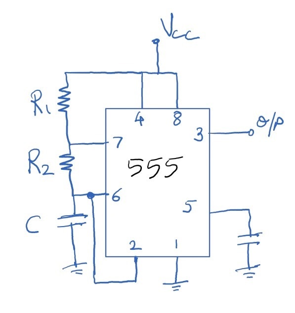
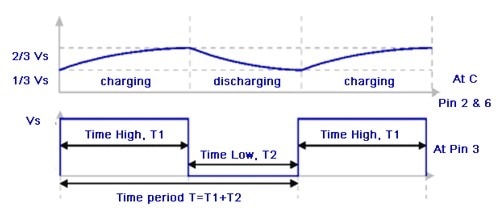
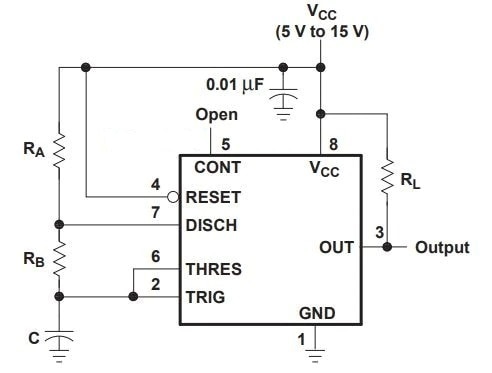
Hence, there was a need to somehow convert this DC voltage into a time varying voltage waveform. One solution to this is use an opamp based voltage to frequency converter. Another method is to use a 555 timer IC in astable mode and replace one of the resistors with a thermistor or any other sensor that produces change in resistance in response to stimulus.
| {gallery}My Gallery Title |
|---|
|
|
|
|
 |
|
|
Ludicrous 555 by wolfgangfriedrich
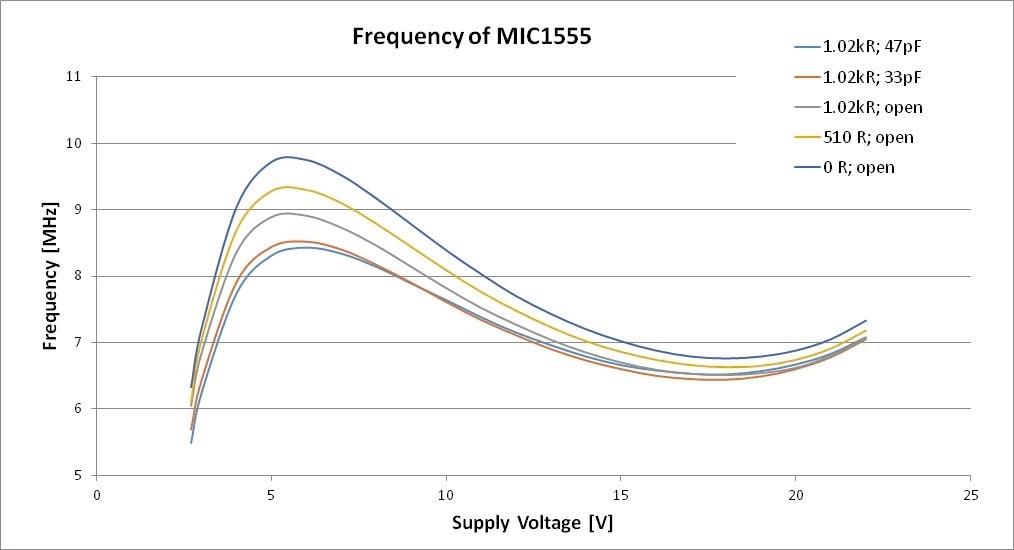
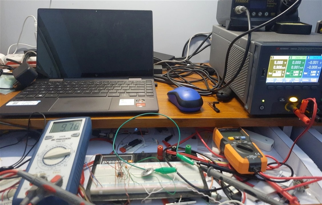
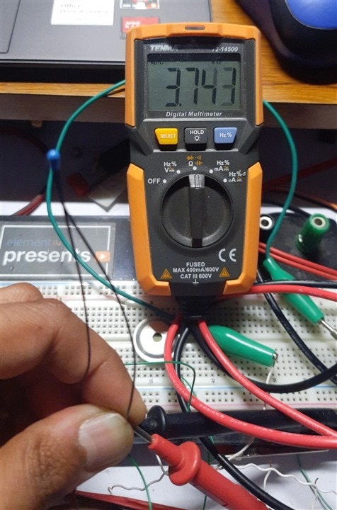
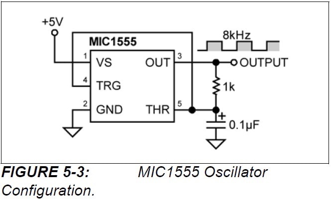
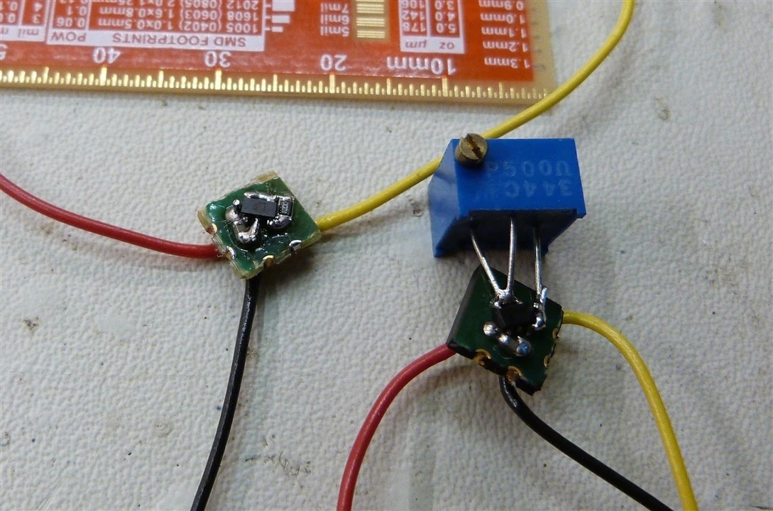
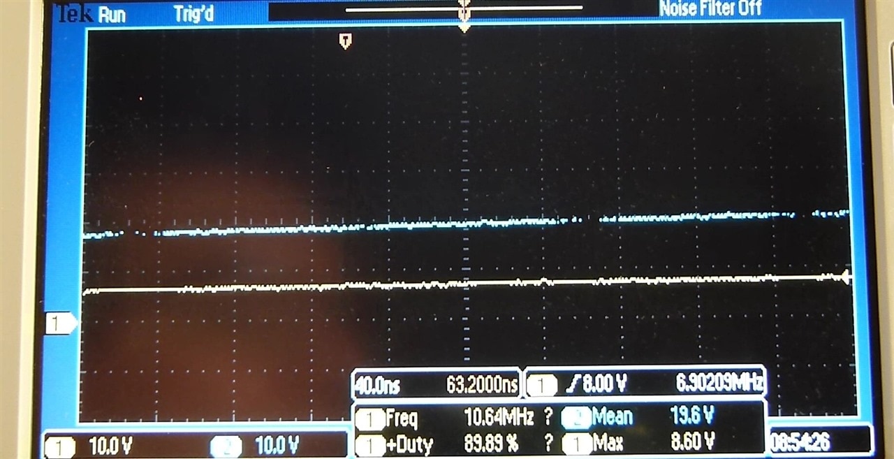
The humble 555 timer started its life as a bipolar IC. Technology progressed and CMOS type 555 timer chips are available now. The fastest one he could find is the Microchip “IttyBitty” MIC1555. His quest was to find out how fast it can really go. The MIC1555 can be used in astable oscillator configuration and the datasheet specifies a maximum frequency of 5 MHz with a 1 KOhm resistor and 47 pF capacitor.
He built up the circuit on a tiny breadboard to minimize those pesky parasitic capacitances. With 1 KOhm and 47 pF he did a voltage sweep in the recommended operation range from 2.7 V to 18 V and beyond the the absolute maximum rating of 22 V. Turns out he already got 8.43 MHz at 6 V as a maximum frequency. Successively reducing the resistor and capacitor values to 0 Ohm and open circuit instead of a capacitor increased the frequency further to 9.75 MHz at about 6V. Interesting side note, that the frequency reaches a minimum at the specified max operation frequency of 18 V and increases again when going higher than that inside the absolute maximum range. He also recorded the current draw and duty cycle for all test setups. No surprises there, the current increases with the voltage and the duty cycle decreases.
| {gallery}My Gallery Title |
|---|
|
|
|
|
 |
|
|
Honorable Mention:
The following projects received votes from our judges:
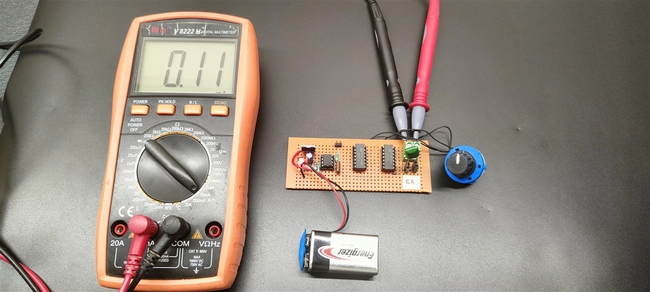
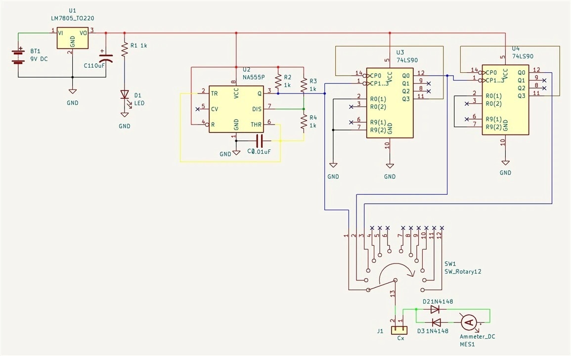
Capacitance Meter Using 555 and Decade counter by vinayyn
| {gallery}My Gallery Title |
|---|
|
|
|
|
|
|
|
|
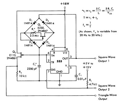
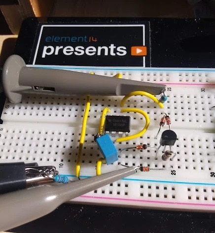
Walter June’s 555 Triangle Waveform Oscillator by scottiebabe
| {gallery}My Gallery Title |
|---|
|
|
|
|
|
|

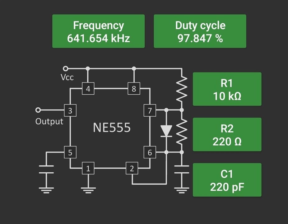
ADC using 555 timer by Sundeep AJ
| {gallery}My Gallery Title |
|---|
|
|
|
|
 |
|
|


Top Comments