


Limitations for my Roadtest
The RX65N MCU operates at a voltage from 2.7V to 3.6V. The 12-bit ADC analog input pins voltage is AVss <= Vpin <= AVcc. AVss and AVcc do not need to be tied to Vcc. On the Envision board, VCC = AVcc = 3.3V; Vss =AVss = 0V. There are two 12-bit conversion units: 0 and 1; thus, AVSS0; AVCC0; AVSS1; AVCC1. The Arduino pins are tied across both groups.
Therefore, voltage on the Analog pins must lie between 0V and 3.3V. I was going to connect this to my PSU, but its Vout for analog conversion is set to 0V to 5V: I could do this with a voltage divider I guess but it’s just going to affect the results. Instead, I will do it via a breadboard: I have an INA260 IC that I can plug in to read Voltage and Current (via I2C) plus a thermistor for temperature readings. I can simulate other temperature readings with potentiometers. The Arduino pins provide for both a 5V and 3.3V output which can be used to drive the test circuit, along with an external PSU to drive a range of voltages and currents through the INA260. So, although not quite what I wanted to do, the principle is exactly the same.
Summary of ADC on the RX65N
The MCU provides a 12-bit ADC capability, across 2 units. Unit 0, for high-speed conversion, has 8 channels and Unit 1, for middle-speed conversion, has 21 channels plus a temperature sensor (for the CPU) output and internal reference voltage. It uses successive approximation to produce the result. It can operate in:
- Single scan mode: input channels are converted in ascending order: 0-7; 0-20.
- Continuous scan mode: input channels are continuously converted in ascending order: 0.7; 0-20
- Group scan mode: the 8/21 channels are divided into two or three groups - A & B; A, B & C - and converted in ascending order in each group
Group scan mode is interesting. Priority scanning can be assigned to group scan mode and a higher priority interrupts a lower priority: Group A > Group B > Group C. This would allow you to assign what you consider a more important conversion to be made, overriding others. For example, if I was using ADC conversion for Voltage and Current (rather than I2C) then I could prioritise this to be higher than the ADC for temperature conversions on the basis that a PSU user is likely to be more interested in V and A than degrees C. Similarly, I could prioritise the temperature reading of the Linear Regulators higher than the temperature readings of the Bridge Rectifier on the basis that the former will run hotter, and thus be more likely to reach operational limits first. To make this all work of course, priority triggers cannot ALWAYS override the lower priority triggers otherwise they’d never be read: care and consideration to the triggers must be given.
Types of triggers for the ADC are:
- Software trigger
- Synchronous trigger: triggers by timers built into the MCU
- Asynchronous trigger: triggers by external triggers tied to a pin for each Unit (thus, two asynchronous triggers, one for each unit)
Conversion speed depends on the resolution mode configured, and assuming the AD conversion clock is running at 60MHz:
- 12-bit: 0.48uS per channel
- 10-bit: 0.45uS per channel
- 8-bit: 0.42uS per channel
There are other features, but these are the main ones.
There is a FIT module for the ADC with an application note describing how to configure and use it. There is a demo available for a number of MCUs/boards, but not the RX65N or Envision board. However, the ADC functionality for the RX65N is shared with the RX64M and RX71m so the demos should be adaptable from the RSK board they are designed for. And indeed they are, with minimal change.
I have set up a demo project to get this working using the Arduino headers I’ve soldered onto the board and a potentiometer to adjust the voltage. Here’s a sketch of the circuit:
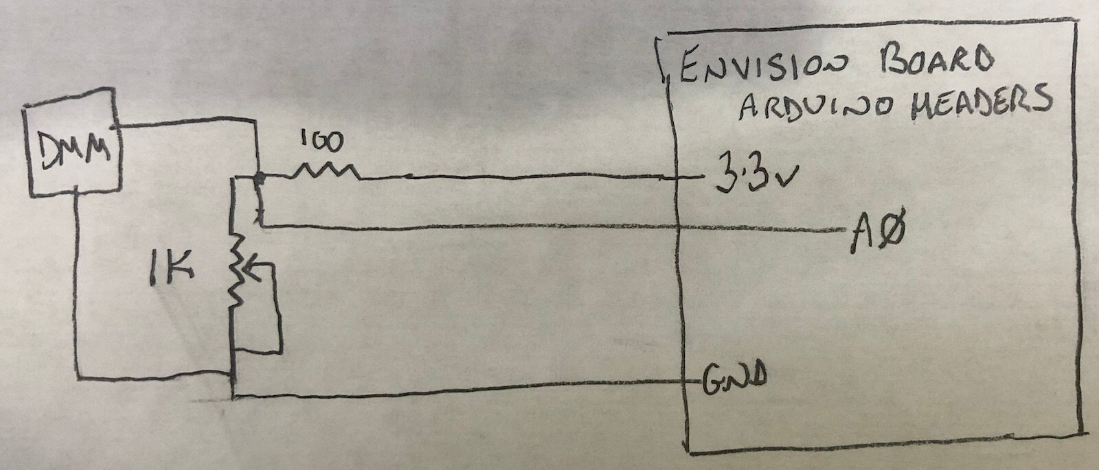
And here’s a (TBH, not very interesting) video of it running. I’m using a multi-turn pot and haven’t gone down to zero otherwise I’d completely lose you all! In retrospect, I should have increased the font size, but I think you'll get the idea.
As you can see, it’s very accurate - between 0 and 5mV different between the conversion and DMM reading. It remained this accurate throughout the full range of the pot.
The code is set up to trigger a reading on a timer, with the actual display of value/reading made through a callback. I’m taking 10 readings before displaying anything: this slows it down to make it easier to see but also improves the accuracy as the ADC is storing and averaging results. The flashing “*” is just an indicator of the timer unit triggering (it’s actually toggling every 10 triggers). I’ve zipped the project and attached it below.
Summary Thoughts
This was simple to get from a demo to an alternate working project for the Envision board. I’m impressed with the accuracy as well. Apart from that, there’s not much more to say in terms of the demo itself. The ADC functionality looks to be rich although I doubt I’ll use all the features for this road test.
Further Entries
I will update this entry to provide links to further instalments as I create them:
Part Three: Development Software
Part Four A: Smart Configuration
Part Four C: Segger emWin Introduction
Part Four D: Removal of the LCD
Part Four E: Analog to Digital Conversion (this post)
Part Five: Static Setup of the GUI
Part Six: Getting the Display Working
Part Seven: USB/Serial Interface
Also, worth reading Jan Crump's road test as he's taking a more technical approach.