element14 Community
element14 Community
    Register Log In
  • Site
  • Search
  • Log In Register
  • Members
    Members
    • Achievement Levels
    • Benefits of Membership
    • Feedback and Support
    • Members Area
    • Personal Blogs
    • What's New on element14
  • Learn
    Learn
    • eBooks
    • Learning Center
    • Learning Groups
    • STEM Academy
    • Webinars, Training and Events
  • Technologies
    Technologies
    • 3D Printing
    • Experts & Guidance
    • FPGA
    • Industrial Automation
    • Internet of Things
    • Power & Energy
    • Sensors
    • Technology Groups
  • Challenges & Projects
    Challenges & Projects
    • Arduino Projects
    • Design Challenges
    • element14 presents
    • Project14
    • Project Groups
    • Raspberry Pi Projects
  • Products
    Products
    • Arduino
    • Avnet Boards Community
    • Dev Tools
    • Manufacturers
    • Product Groups
    • Raspberry Pi
    • RoadTests & Reviews
  • Store
    Store
    • Visit Your Store
    • Or choose another store...
      • Europe
      •  Austria (German)
      •  Belgium (Dutch, French)
      •  Bulgaria (Bulgarian)
      •  Czech Republic (Czech)
      •  Denmark (Danish)
      •  Estonia (Estonian)
      •  Finland (Finnish)
      •  France (French)
      •  Germany (German)
      •  Hungary (Hungarian)
      •  Ireland
      •  Israel
      •  Italy (Italian)
      •  Latvia (Latvian)
      •  
      •  Lithuania (Lithuanian)
      •  Netherlands (Dutch)
      •  Norway (Norwegian)
      •  Poland (Polish)
      •  Portugal (Portuguese)
      •  Romania (Romanian)
      •  Russia (Russian)
      •  Slovakia (Slovak)
      •  Slovenia (Slovenian)
      •  Spain (Spanish)
      •  Sweden (Swedish)
      •  Switzerland(German, French)
      •  Turkey (Turkish)
      •  United Kingdom
      • Asia Pacific
      •  Australia
      •  China
      •  Hong Kong
      •  India
      •  Korea (Korean)
      •  Malaysia
      •  New Zealand
      •  Philippines
      •  Singapore
      •  Taiwan
      •  Thailand (Thai)
      • Americas
      •  Brazil (Portuguese)
      •  Canada
      •  Mexico (Spanish)
      •  United States
      Can't find the country/region you're looking for? Visit our export site or find a local distributor.
  • Translate
  • Profile
Embedded and Microcontrollers
  • Technologies
  • More
Embedded and Microcontrollers
Blog Renesas RX65 Envision Kit - part 9: UART
  • Blog
  • Forum
  • Documents
  • Polls
  • Files
  • Members
  • Mentions
  • Sub-Groups
  • Tags
  • More
  • Cancel
  • New
Embedded and Microcontrollers requires membership for participation - click to join
Blog Post Actions
  • Subscribe by email
  • More
  • Cancel
  • Share
  • Subscribe by email
  • More
  • Cancel
Group Actions
  • Group RSS
  • More
  • Cancel
Engagement
  • Author Author: Jan Cumps
  • Date Created: 8 Dec 2019 1:17 AM Date Created
  • Views 1926 views
  • Likes 5 likes
  • Comments 7 comments
  • rx65n
  • usb
  • rt
  • renesas
  • sci
  • uart
  • road_test
  • ftdi
Related
Recommended

Renesas RX65 Envision Kit - part 9: UART

Jan Cumps
Jan Cumps
8 Dec 2019

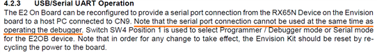
Preface: It seems that it's not possible to use the debug USB port as debugger and serial port at the same time.

image


I'm evaluating the Renesas RX65N MCU EV Kit.

In this post: Serial communication - UART - SCI.

image


The RX family has 12 serial peripherals. Luxury. And the RX65N supports all of them.


* CH#  110 111 113 130 210 230 231 23T 24T 24U 63N 631 64M 71M 65N

* ---  --- --- --- --- --- --- --- --- --- --- --- --- --- --- ---

* CH0          X  X  X  X  X              X*  X  X  X  X

* CH1  X  X  X  X  X  X  X  X  X  X  X  X  X  X  X

* CH2          X                              X  X  X  X  X

* CH3                                          X  X  X  X  X

* CH4                                          X  X  X  X  X

* CH5  X  X  X  X  X  X  X  X  X  X  X  X  X  X  X

* CH6          X  X  X  X  X      X  X  X  X  X  X  X

* CH7                                          X  X  X  X  X

* CH8          X  X  X  X  X          X  X  X          X

* CH9          X  X  X  X  X          X  X  X          X

* CH10                                          X  X          X

* CH11                                      X  X  X          X

* CH12  X  X  X  X  X  X  X              X  X  X  X  X


These blocks can be used as SCI/UARTs, I2C or SPI devices.

On the Envision board, SCI channel 5 is connected to the debug USB port.

Channel 9 is broken out to the PMOD connector. Other ones are availabe from different locations on the board too.

In this example I'm using SCI channel 9. That allows me to keep using the debug USB for debugging.

A logic level to USB converter is required. There are (FTDI) cables that can do that (or a Bus Pirate). I'm using the debug section of a TI LaunchPad.


image


image


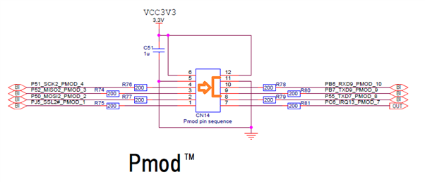
PMOD pin 10 is RX, pin 9 TX and pin 11 GND. With these 3 pins you can make a connection to your logic -> USB converter.


Renesas' RX65 example


The SCI application note for SCI comes with an example for a different RX65N board. That board has SCI2 linked to the USB and runs a 24 MHz crystal clock.

In our case, SCI2 is linked o USB and the crystal is a 12 MHz one.

Because we're using channel 9 and a different clock, there are some changes to be made:


in r_config/r_bsp_config.h, change the crystal frequency from 24 MHz to 12 MHz:


/* Input clock frequency in Hz (XTAL or EXTAL). */
#define BSP_CFG_XTAL_HZ                 (12000000)


Then, in r_config/r_sci_rx_config.h, enable serial channel 9:


#define SCI_CFG_CH9_INCLUDED    (1)


In the main() function, adapt the init code to use channel 9:


    my_sci_err = R_SCI_Open(SCI_CH9, SCI_MODE_ASYNC, &my_sci_config, my_sci_callback, &g_my_sci_handle);


Also change the LED flash functionality in the SCI interrupt handler.

The LED toggles whenever you send a character to the SCI.

Our board has user LED2 linked to Port 7 pin 0:


In r_bsp/board/rskrx65n_2mb/rskrx65n_2mb.h, alter the definitions of LED 2:


/* LEDs */
// ...
#define LED2                PORT7.PODR.BIT.B0
// ...
#define LED2_PDR            PORT7.PDR.BIT.B0


In the SCI callback, also change to LED2:


    if (args->event == SCI_EVT_RX_CHAR)
    {
        /* From RXI interrupt; received character data is in args->byte */
        LED2 = ~LED2;         // Toggle LED to demonstrate callback execution.
    nop();
    }


Then, change the pin assignment function to use channel 9:


static void sci_rx65N_2M_init_ports(void)
{
    R_BSP_RegisterProtectDisable(BSP_REG_PROTECT_MPC); // Use BSP function to unlock the MPC register.

    // jc 20191207:
    // TXD9 PB7 78
    // RXD9 PB6 79

    /* Initialize channel 9 TXD and RXD pins */
    PORTB.PODR.BIT.B7 = 0;      // Set PB7(78) signal state low (power-up default)
    MPC.PB7PFS.BYTE = 0x0A;     // Assign PB7(78) to TXD2 function
    MPC.PB6PFS.BYTE = 0x0A;     // Assign PB6(79)) to RXD2 function

    R_BSP_RegisterProtectEnable(BSP_REG_PROTECT_MPC); // Re-lock the MPC register.

    PORTB.PDR.BIT.B7 = 1;       // Set PB7(78) direction to output (for use as TXD)
    PORTB.PDR.BIT.B6 = 0;       // Set PB6(79) direction to input (for use as RXD)
    PORTB.PMR.BIT.B7 = 1;       // Set PB7(78) mode to peripheral operation
    PORTB.PMR.BIT.B6 = 1;       // Set PB6(79) mode to peripheral operation

    return;
}


Test


To test the example, you have to connect your USB -> logic level translator to the PMOD connector.

Use the below table as guideline.


PMOD pinRX65N Function
PMOD 9SCI 9 TX
PMOD10SCI 9 RX
PMOD 11GND


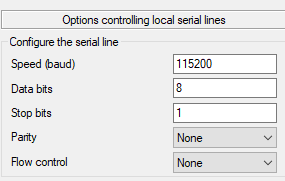
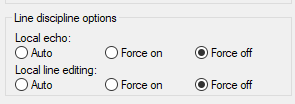
Then use a serial terminal program to connect to that translator, speed 115200, no parity, 1 stop:

image


Set the traffic for no cho. The firmware will echo when needed:


image

Connect, Then start the program.

You need to type "any key" (use enter) to start the communication.

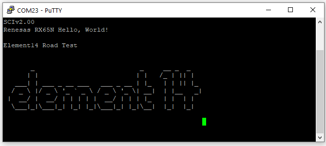
First, the terminal will show the SCI FIT module version:

image


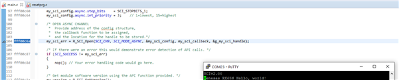
After that, each character you type in the terminal will be echo'd by the device.

If the LED2 does not flash when you type a character in your terminal, swap the RX and TX connections and try again.


The e2 studio project is attached.


Related blog
part 1: Create an Empty Project
part 2a: Blinky with GCC Toolchain
part 2b: Blinky with Timer and Interrupt
part 3: Port an example from Renesas toolchain to GCC
part 4a: Low Power - Sleep
part 4b: Low Power - Software Standby
4c todo: power mode 3
4d todo: power mode 4
part 5: DAC
part 6: Software SHA
part 7: Blinky with FreeRTOS
part 8: DMA
part 9: UART
part 10: Reserve LCD Frame Buffer in Expansion RAM with GCC
part 11: port emWIN to GCC and run an LCD Widget
Renesas RX65N MCU EV Kit - Review
Andrew Johnson's blog series
Renesas Envision Kit RPBRX65N Roadtest
Attachments:
sci_demo_rskrx65n_2m.zip
  • Sign in to reply

Top Comments

  • Jan Cumps
    Jan Cumps over 3 years ago +2
    Here's a capture of the TX signal when it sends the version string in the begin.
  • olympus317
    olympus317 over 1 year ago in reply to Jan Cumps

    Hi, i'm trying to get serial communication to work along with HMI, so far i made a simple GUI and tried to send data from a button, but didn't work, so i tried to replicate your LED indicator but from my generated code and folders, there is no rskrx65n_2mb folder, where else can i find the declaration for LED2?

    ps. using smart configurator i've opened the port 7 pin 0 as you say (and works with your code) but the description is SDCLK, is this ok? 

    • Cancel
    • Vote Up 0 Vote Down
    • Sign in to reply
    • More
    • Cancel
  • olympus317
    olympus317 over 1 year ago in reply to Jan Cumps

    thanks! :D

    • Cancel
    • Vote Up 0 Vote Down
    • Sign in to reply
    • More
    • Cancel
  • Jan Cumps
    Jan Cumps over 1 year ago in reply to olympus317

    I used emWin for the HMI on my kit - with Renesas' examples. No serial communication.

    • Cancel
    • Vote Up 0 Vote Down
    • Sign in to reply
    • More
    • Cancel
  • Jan Cumps
    Jan Cumps over 1 year ago in reply to olympus317

    Serial communication is fairly standard. You should be able to talk back and forth if you configure an UART on both with the same settings, and connect ground to ground, and both RXes to the other sides TXes.
    I have only used this Renesas controller here. What you see in the blog is what I know.

    • Cancel
    • Vote Up 0 Vote Down
    • Sign in to reply
    • More
    • Cancel
  • olympus317
    olympus317 over 1 year ago in reply to olympus317

    with that example, how could i upload an HMI?

    • Cancel
    • Vote Up 0 Vote Down
    • Sign in to reply
    • More
    • Cancel
>
element14 Community

element14 is the first online community specifically for engineers. Connect with your peers and get expert answers to your questions.

  • Members
  • Learn
  • Technologies
  • Challenges & Projects
  • Products
  • Store
  • About Us
  • Feedback & Support
  • FAQs
  • Terms of Use
  • Privacy Policy
  • Legal and Copyright Notices
  • Sitemap
  • Cookies

An Avnet Company © 2023 Premier Farnell Limited. All Rights Reserved.

Premier Farnell Ltd, registered in England and Wales (no 00876412), registered office: Farnell House, Forge Lane, Leeds LS12 2NE.

ICP 备案号 10220084.

Follow element14

  • X
  • Facebook
  • linkedin
  • YouTube