


Introduction
In this episode, we will see how in practice I have set up the 7of9 MDK (the Mannequin Development Kit) and how I have used it to create the first beta upgrade of the project. It involved hardware and software changes and new implementations and I should thank the user's participation commenting the previous posts, as well as suggestions and questions that helped me to depict the right scenario.
In particular, I should thank at dubbie for insisting on the eye features that pushed me in making it as much better as possible. Sometimes, – I suppose it happens not to me only – I will find excuses to avoid adding further complexities to the projects. Also when these are so impacting that can change the game at all; are just the comments that give a new impulse to complete or refine a detail. Thanks to the suggestion of shabaz too about the light around the eye approach. He was right, the idea of the LEDs was already in my mind but seeing it in an example this saved me more time to experiment; as a matter of fact, I had not considered the power of the hot glue as a light diffuser and I was thinking on how to 3D print a sort of diffuser while the easier solution he suggested was perfect.
The MDK in Practice
Let me spend only a few words on the development kit. I have just re-created the electronic part of the architecture on the bench; this resulted useful for the creation of the new components and making software upgrades as the original oper lives at Art-a-Tronica exhibition, but not only. It was just spending time seeing how the parts I have already done were working that I have focused the steps ahead, keeping coherence with the project and trying and testing the best solution.
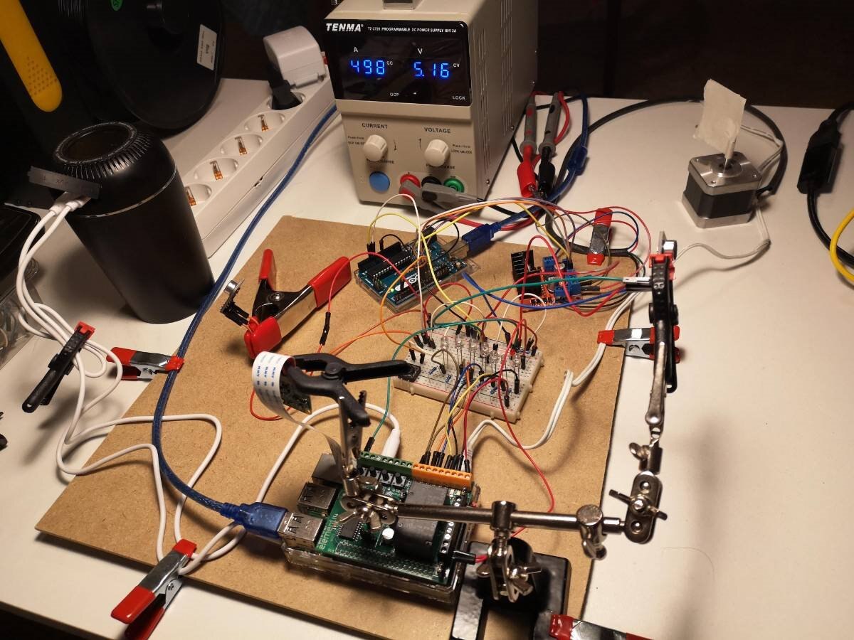
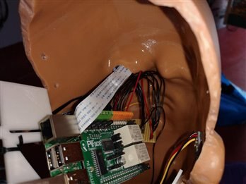
As shown in the above image, all the parts of the project are already connected: The raspberry PI with the camera and the PiFace Digital 2 board, the Arduino, the two left and right microphones, the motor controller and the stepper motor and the audio out. To emulate the motor end-stop switch I have used just a temporary switch button. Connection testing is done using a small breadboard.
An Example of MDK use: Streaming the Pi Camera
One of the uses of the Raspberry PI camera should be streaming some live moments. To reach the right solution I had to test several different ways for both the cases of online and LAN streaming. Without a development platform to make tests installing and removing different programs finding the simplest, replicable and reliable solution was an incredibly time-consuming task. I don't go in depth with too many details as experiments are at a very early stage. The material and procedure are not so simple and it will be the main topic of one of the next posts.
The Eye Light: I Have the Problem but Also the Solution
Despite the incompatibility problem of the NeoPixel library with the Stepper library as discussed in Episode 6, Seein the solution I have adopted now I am almost sure that in this particular context the NeoPixel ring was not the right choice.
The first approach was to use three other pins of the Arduino and a shift register. I have also developed in past a Multiple Shift-Out Registers for Arduno, including the board and PCB.
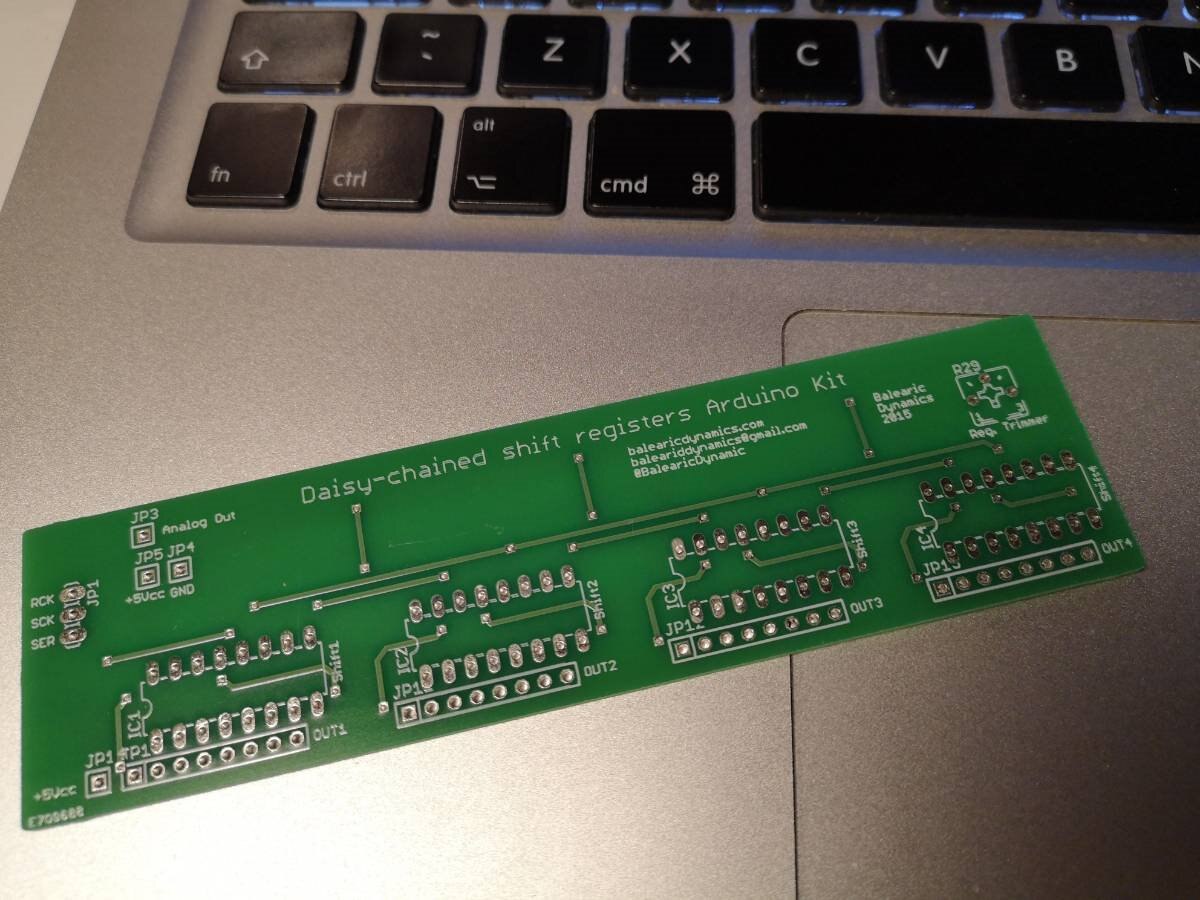
Some of them are already here around and I have plenty (some hundred) of shift registers, so why not? The naswer is simple: because as much a solution is simple, as much it is elegant. I am not a fanatic of the hardware redundancy and if I can reach the same result with less stuff, the solution is better. And everything was under my eyes from the starting of the project. The PiFace Digital 2 board has eight open-collector pins while I use only one (pin zero) connected to the relay for the internal Burning light. So, also thanks to the particular shape of the Eye implant, 7 LEDs are more than sufficient (I should admit that it will be impossible to place more than seven LEDs without using SMD components).
Hardware
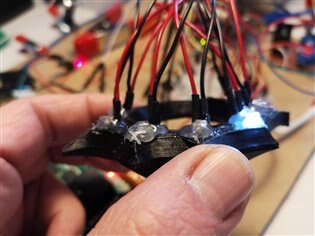
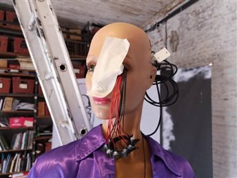
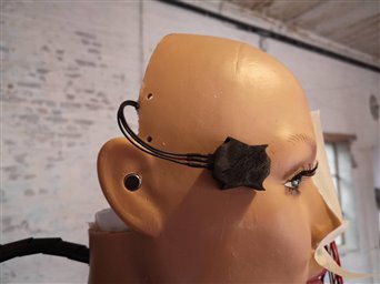
The seven LEDs have been hot-glued to the seven curved vertices of the eye implant: the 3.5 mm LEDs fits perfectly. To get the better effect – also considering the multicolored environment of the character – I have used clear white high-intensity LEDs and a 68 Ohm limiting resistors (calculated values for the LEDs).
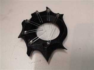
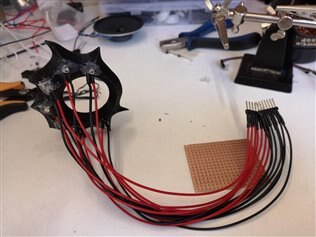
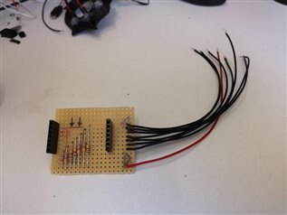
As mentioned in a previous post, all the electronics and wiring has been conceived to be relatively easy to modify and upgrade, repair, etc. Also, in this case, the wires of the eye LEDs have been set to connect internally to a small PCB with the pull-up resistors; all the positive wires (red) are collected to a single cable to be connected to the PiFace Digital 2 +5V while the seven ground wires (black) are connected to the remaining seven open collector pins of the PiFace Digital 2.
As shown in the short video below, the bench test worked well and the light motion effect shown is expected.
Software
Without forgetting the limitation of writing only Python3 scripts, due to the PiFace Digital 2 issue, also for the eye lights, I kept the logic of independent commands that will be connected together by the interaction and the internal logic based on some timing sequences and other events that will occur inside or nearby to 7 of 9. In detail, I have modified the firelights.py script powering on the internal fire light lamp, scheduled on the cron activity register every five minutes. To make the things interesting I have added several sequences of the lights that are executed by this scheduled command, while the firelight is on.
Every function creates a different light pattern (not necessarily rotating) and in this version is executed in sequence; as there are seven LEDs I have also added the function fibonacci that light the LEDs in the sequence 0 (= all Off), 1, 1, 2, 3, 5  shown below. As usual, the updated software is available on the GitHub repository under the Raspberry folder.
# Executes the Fibonacci sequence up to 5
# on the 7 LEDs (0, 1, 1, 2, 3, 5}
# Note that the first pause is for 0 of the sequence
def fibonacci():
    pause = 0.025 # ms delay between every light sequence

    # 0
    time.sleep(pause)

    # 1
    pfio.digital_write(7, 1)
    time.sleep(pause)
    pfio.digital_write(7, 0)
    time.sleep(pause)

    # 1
    pfio.digital_write(7, 1)
    time.sleep(pause)
    pfio.digital_write(7, 0)
    time.sleep(pause)

    # 2
    pfio.digital_write(6, 1)
    time.sleep(pause)
    pfio.digital_write(6, 0)
    time.sleep(pause)

    # 3
    pfio.digital_write(5, 1)
    time.sleep(pause)
    pfio.digital_write(5, 0)
    time.sleep(pause)

    # 5
    pfio.digital_write(3, 1)
    time.sleep(pause)
    pfio.digital_write(3, 0)
    time.sleep(pause)
The scriptlet below, instead, shows the sequence of the calls, scheduled every five minutes.
# -------------------------- Main process
fireLight(True)
clearLeds()
fibonacci()
clearLeds()
# Loops on the seven LEDs
for j in list(range(ledRotations)):
    rotateLeds(1)

clearLeds()

for j in list(range(ledRotations)):
    rotateLeds(-1)

clearLeds()
fibonacci()
clearLeds()

# Calculate the random number or double rotations
randRange = randint(ledMinRotations, ledMaxRotations)

for j in list(range(randRange)):
    rotateLeds(1)
    rotateLeds(-1)

clearLeds()
fireLight(False)

# -------------------------- END
Following the logic of the project, it has a sense that the eye lights events sequence is executed autonomously from all the other tasks and interactions. As a mater of fact, it represents the connection with the colony every Borg do periodically.
Arming 7 of 9
Another light feature added to the head is a laser, the light arm of every Borg. I plan to use several sensors together to the laser next weeks so I decided to buy a set of sensors all-together. I got a 37 sensors package from Elegoo and I should admit that it was a very good selection. Excluding a push button (maybe 36 was a bad number?) all the other components were very useful.
Hardware
I designed a small case to host the Laser following the same style of the eye design and 3D printed two shells to include the small sensor.
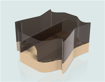
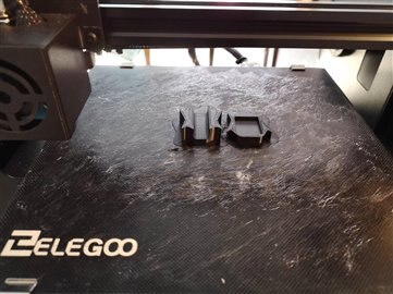
The images below show the assembling sequence and testing of the device.
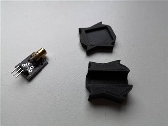
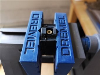
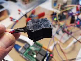
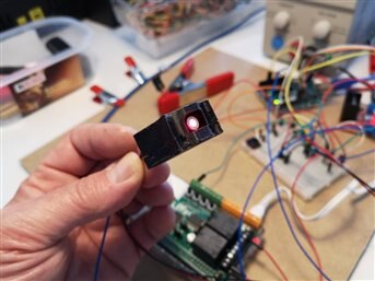
The laser sensor is controlled by Arduino through a PWM pin so it is possible to vary the intensity of the emission. The small collimation lens can focus a 10 square cm at a distance of about 10 meters.
Software
I have added the laser control functions to the main Arduino loop mixed together with the motor rotation. As the PWM digital write does not impact with the hardware interrupts manage by the stepper Arduino library it works fine.
laser.h header file defines parameters and the laser control structure
/**
  Laser status structure.
*/
typedef struct LaserStatus {
  int value;          ///< current laser value
  boolean isOn;       ///< Laser status on/off
};

#define LASER_ON 1      ///< Laser is powered on
#define LASER_OFF 0    ///< Laser if powered off
#define LASER_DEFAULT 16   ///< Default laser value
#define LASER_FIRE 255     ///< Laser fire value (also when burst
#define LASER_FIRE_DURATION 1000    ///< Laser fire shot duration (ms)
#define LASER_OFF_BEFORE_FIRE 50    ///< Delay after powering out the laser before firing
#define LASER_BURST_DURATION 50     ///< Duration of a single burst
#define LASER_BURST_PAUSE 25     ///< Duration of a single burst
#define LASER_BURST_LENGHT 3       ///< Number of bursts
#define LASER_LONG_BURST 5        ///< Number of multiple bursts
#define LASER_FADE_DELAY 25      ///< Fade steps delay (ms)
A series of functions to create several laser patterns have been added to the sketch. The calls are managed by the main loop as sown in the scriptlet below.
  burstLaser();
  delay(1000);
  longBurstLaser();
  delay(1000);
  fireLaser();
  delay(1000);
  laser.value = 128;
  laserFadeOff();
  delay(1000);
  laser.value = 128;
  laserFadeOn();
  delay(1000);
  laser.isOn = LASER_OFF;
  setLaser();
  delay(1000);
Installing the Updates
After setting the software on the test bench and completed the hardware, the last step has been adding the components to 7 of 9. The images below show the sequence of the update.
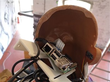
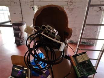
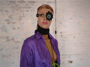
The short video below shows the suggestive effect generated by the new components.
Top Comments
-

balearicdynamics
-
Cancel
-
Vote Up
+3
Vote Down
-
-
Sign in to reply
-
More
-
Cancel
Comment-

balearicdynamics
-
Cancel
-
Vote Up
+3
Vote Down
-
-
Sign in to reply
-
More
-
Cancel
Children