


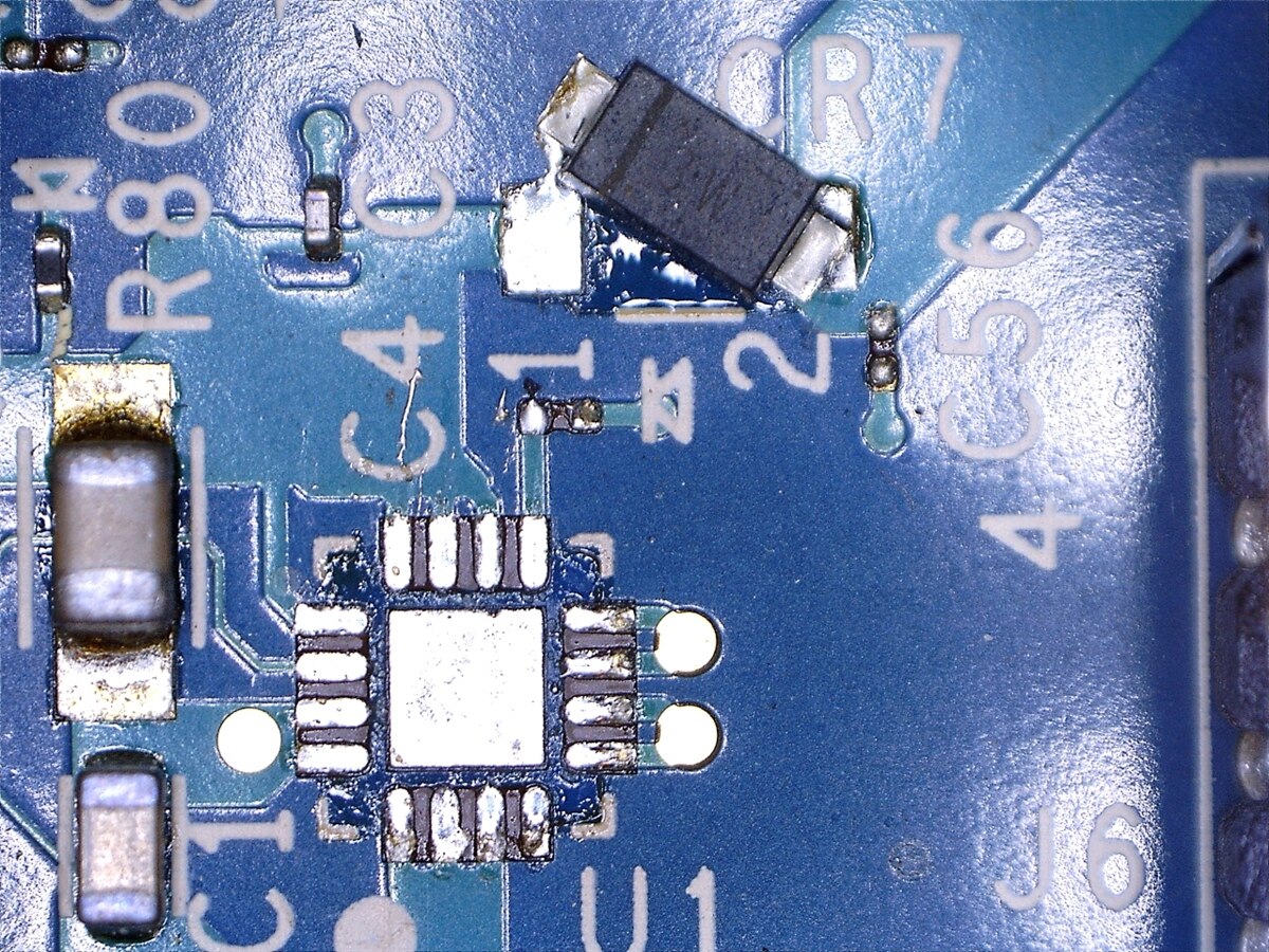
Back in First Steps - Intel Edison step 4 I reported that for some reason the External DC switcher IC has expired on the Intel Edison Arduino Interface board.
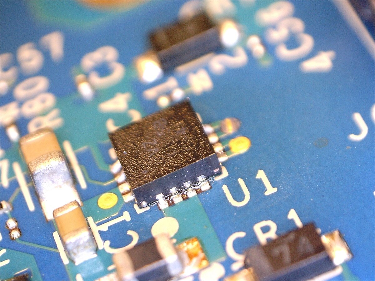
I managed to get a picture of the dead object.
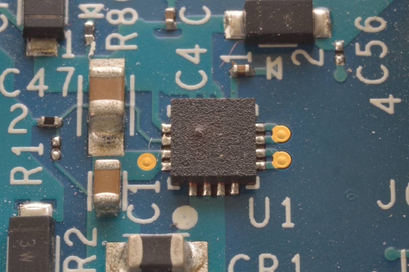
Looks like it has a bubble on the top and it definately doesn't work.
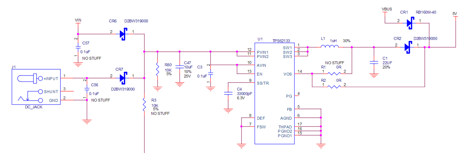
The schematic is available
http://www.intel.com/content/dam/support/us/en/documents/edison/sb/edison_arduino_hvm_8_26.pdf
U1 is the dead item
So I ordered a couple of replacements (and a few other items)
TI 5v SwitcherTI 5v Switcher
I held off doing anything until I was finished writing the previous blogs, and the parts arrived.
Yesterday I took the parts and board into work, and had a talk with our workshop experts.
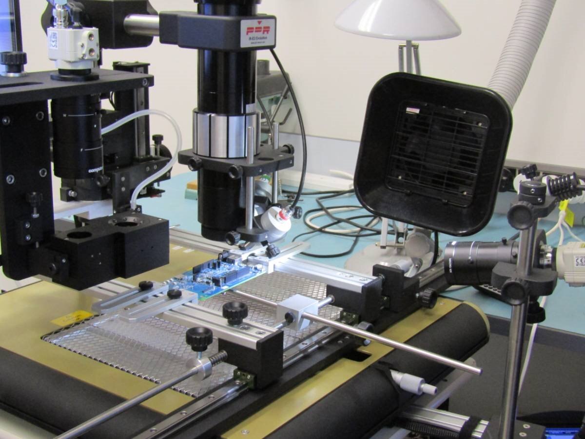
Reflow machine
I was very surprised that there were two options, either "... manual or we can use the new automatic machine..." .....
They had just received this beast and hadn't had the opprtunity to 'practice' on smaller boards.
Sadly it was the day I left my camera behind so I had to borrow one that I had no control over the focal point.
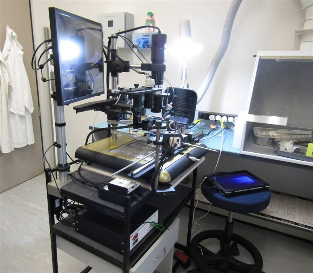
This is a PDR IR-E3 Evolution with vacuum part placement and some clever cameras and bits to ensure the part is placed correctly.
Various profiles are loaded into the tablet, and it looked like a better choice than the manual method which was likely to blow other parts away.
The large lens like device is the component heating and you change the lens to suit the area and then adjust it to the size you want.
The 3 x 3 mm chip size caused a few issues due to the lens size and the connectors located close by. It meant the vacuum placement had to come in through the only gap available, and just cleared the bottom of the lens.
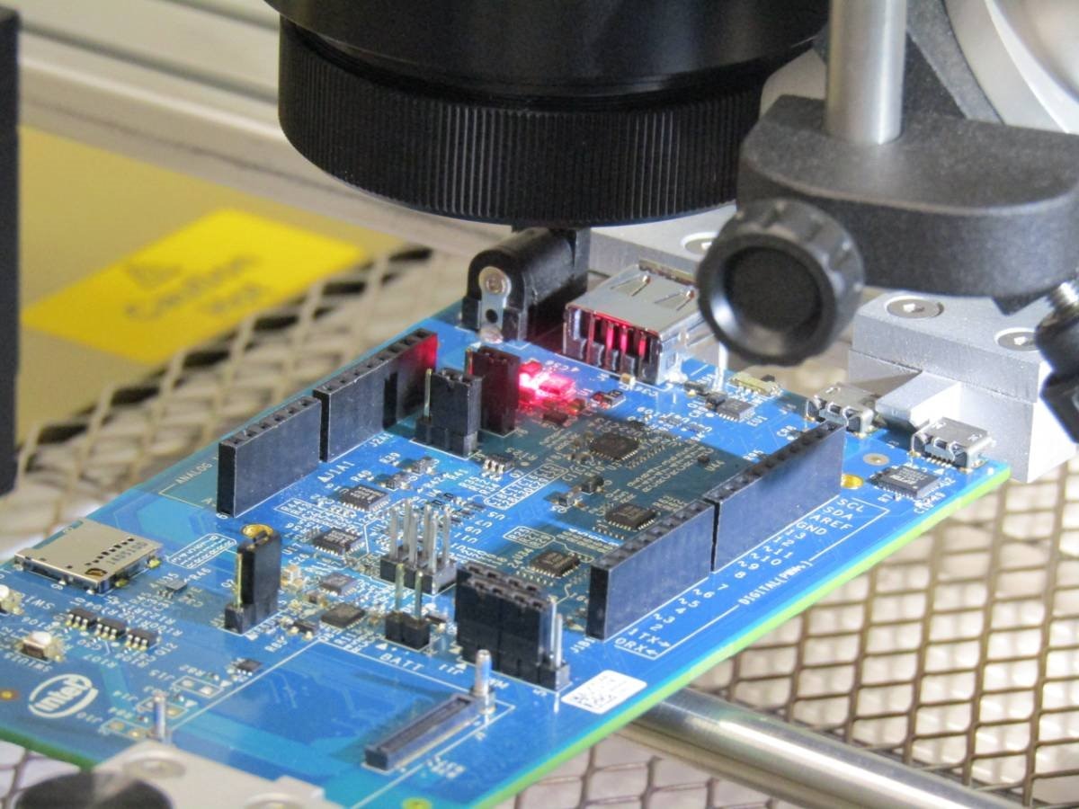
This photo was taken during the alignment phase, where you adjust the board position using two verniers to line it up under the lens and placement tool.
The placement tool enters from the upper left between the 2.1mm DC socket and the headers.
Given what I know now, there is no need for the IR Component heater to be in place during the process if you manually control the pickup and placement.
This picture gives an idea of the components.
On the left is a split mirror camera. This is slide sideways into place and looks down on the board at the component location.
At the same time the component on the bottom of the vacuum pickup is brought over the hole with the LEDs pointing out at 45 deg, and the camera looks at the bottom of it.
You adjust the light levels until you see both the board and component underside.
You adjust the board position and the rotation of the pickup until the two are exactly in the right place.
The camera is shifted out the way and the component placed onto the board.
You can check with the camera to ensure it is correct.
The large lens in the middle is the IR component heater.
There are two temperature probes that you line up on the component location (red) and the board (green), and the feedback from these controls the heating process.
The camera at the front can be moved around to see the progress and works well right up until it gets swamped with the IR light.
The suction filter on the right is part of the fume extraction they fitted into the workshop, and removes fumes, smells and adds some cooling effect.
Removal
The first job was to remove the dead chip.
Despite two different profiles, it refused to budge.
A look at the temperatures showed that it never really reached 250 degrees, and it had a 80% max heating setting, meaning it never would.
Once this had been corrected it came away with tweezers.
A check under the electronic camera showed the board was okay (despite having three heat cycles applied)
The diode got knocked but was an easy fix with the soldering iron.
Reflow
One method of soldering SMD parts is to use a stencil and apply solder paste.
You can follow Shabaz's blog to see his process in making a stencil holder PCB Stencil Printer - Alignment discussion
Obviously that only works for bare boards.
Solder paste is a mixture of flux and tiny solder blobs of a uniform size.
Using a stencil provides an even coating of just enough solder to the pads.
I've heard of people soldering the pad, adding flux, then heating the component.
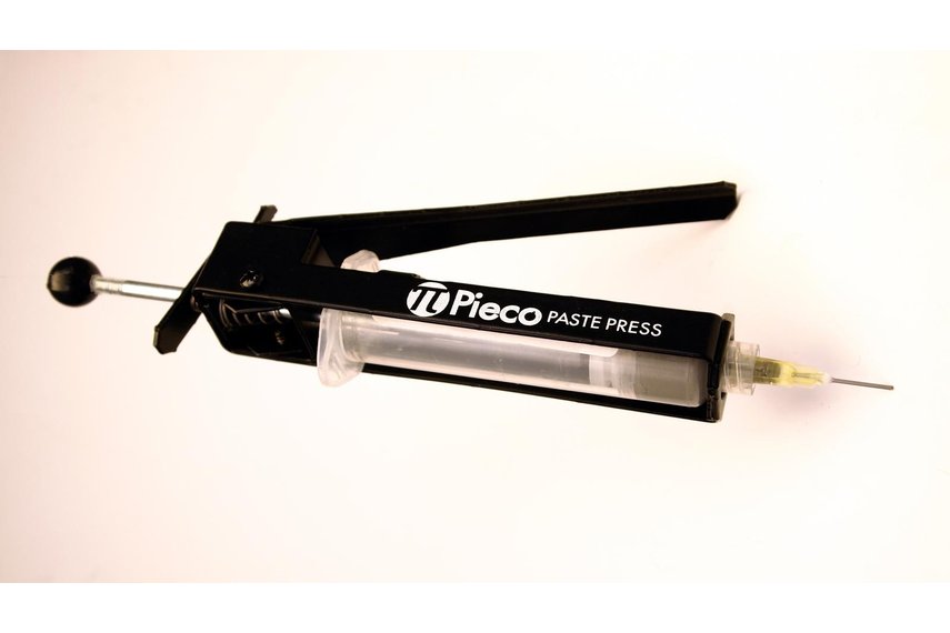
Some people use a solder paste dispenser and squeeze out the estimated amount on the pads.
I've got one of these.
The other method I hadn't heard was to spread a fine layer of paste and place the component on the fine layer.
The IR rework machine has the ability to do this, so we duly spread the paste using the special aluminium block and spreader, added the component, and then tried to suck it up .......
It seems that the size combination was not optimal for lift off, and in the end we resorted to manually placing it on the pad, sucking it up and then aligning everything before placing it exactly in the right place.
This time we chose a profile to suit the solder and let it rip.
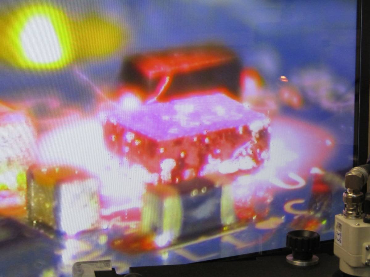
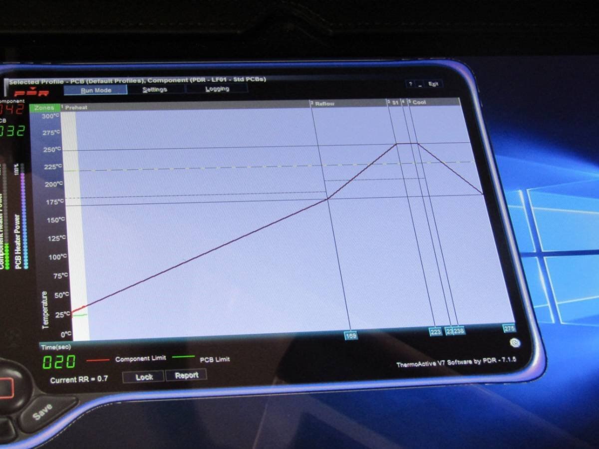
The image taken from the progress camera screen shows the IR energy heating the component.
The bright parts are excess solder paste that migrated around during the various attempts to place the IC correctly (dropping didn't work) with the correct orientation.
For those interested, we worked out that the extra holder was most likely to prevent the board from flexing during the placing process, but the process camera was very useful to see when we had 'touchdown'.
The reflow process is controlled by the profile, and unlike the manual hot air 'hit and miss' approach this is absolutely repeatable.
This gives you an idea of the profile, which is just starting out. (20 secs in)
Finished Job
A check under the microscope again showed some pins may not have been soldered.
It was likely that the solder under the thermal pad was too much and had held the IC a little too high off the board.
For larger IC's with the thermal pad underneath, they often have a via or a trace which helps ensure there is no excess.
An application of liquid flux and another cooking should sort it out, but the reality was it cleaned it up, but didn't move it.
In the end some careful heating with a very fine tip soldering iron made it look perfect.
Testing
Since I had no idea of what caused the problem in the first place, I hatched a plan to use some current limiting to try and spot any issues before destroying the chip/board.
I thought my home supply had current limiting, but it didn't, so I'm going to order some parts to make one like jw0752 which are linked here Comparing Power Supplies
Instead I resorted to using a resistor in series and checking the voltage.
The series resistor didn't work very well, depsite lowering the value more than I wanted to, it really didn't work.
The power light sometimes flicked on, then went off, but if I applied 5v to the 5v pin it seemed to stay on.
It did confirm that the bare board was drawing 4-500mA, so the series resistor was never going to work.
A check with the Ohmeter around the IC showed no shorts and each pin produced the sort of results that indicated it should work.
In the end I applied 7.5v and it happily produced 5v at 600mA.
Once the voltage rose to 10v it dropped back to 500mA and at 12v it was 4-450mA.
Sadly once the voltage hit 15v, it drew max current and it was game over.
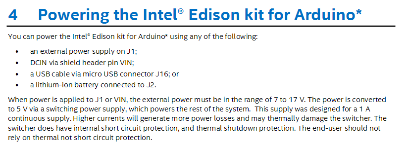
Specs
The datasheet for the IC says 7-20v
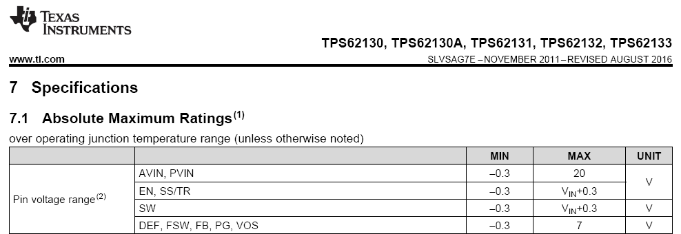
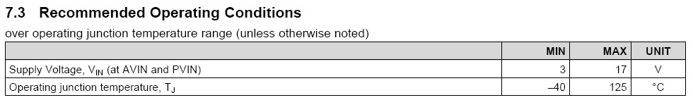
I had it in my mind that the specs suggested a 7-17v power pack could be used.
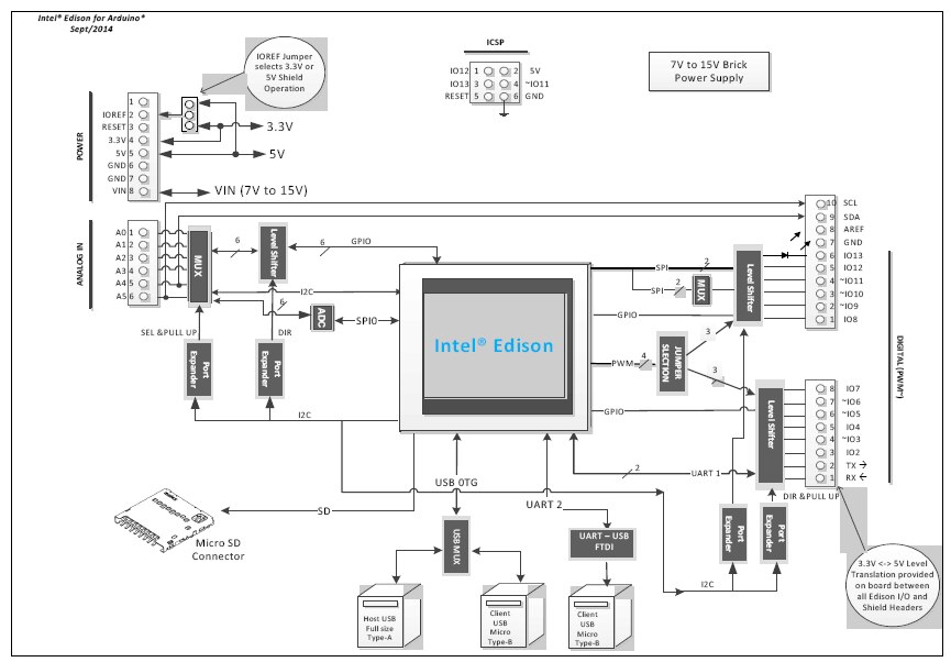
But on checking the schematic it is 7-15v.
it is repeated here.
2.6 Intel Edison kit for Arduino* power supply
Edison is a low power device. In general it will not draw more than 200 mA (approximately 430 mA (final value TBD) when transmitting over Wi-Fi) from the main power source. Therefore, an Intel Edison device may run on USB power (when configured as a device), or off an external power adapter from 7 to 15 V.
BUT here http://www.intel.com/content/dam/support/us/en/documents/edison/sb/edisonarduino_hg_331191007.pdf it is 7-17v
So imagine my surprise when it went short circuit at 15v (using a good supply with a good Fluke meter) ...
Needless to say I've ordered some more IC's (we lost one during the pasting process)
We've decided that we can cook the board once more, and now we've got different solder it should release easier.
Failing that I'll use an external DC to 5v and wire it in place of the IC.
Suggestions
The first suggestion to anyone reading this is USE 12 v ONLY ON J1 or Vin.
J1 has a diode in series, so my measured 15v was really just under that at the IC, and I can only imagine that there is something in the design limiting it.
The next suggestion would be to the document writers to alter the text to match the rest of the limits.
I now think that one of the power packs I used had an open circuit voltage that was above 15v.
They are an older transformer, rectifier and some capacitance, so it's very likely that this caused the initial problem.
The regulators on Arduino's are almost bullet proof, so could well handle the initial unregulated voltage better than ths IC can.
We've now had some experience using a machine that is 12,000 times the price of the item, and learnt a few new tricks along the way.
So it's not all bad.
Cheers
Mark
This started as a simple blog, but has now grown over a few posts, so an index is appropriate.
Top Comments