


|
Previous blogs:
FPGA: Waves 7: Random Sequence Generator
Introduction
In blog 5, I looked at computing a sine using a CORDIC method. It was implemented in an iterated bit-serial fashion in a bid to keep the hardware usage low, though it turned out to be more complex than I had anticipated because of some of the fiddly control necessary.
This time I'm going to have a look at running a CORDIC processor much, much faster with the aim of getting one sample per clock. This will necessitate not only moving to parallel operation but also in-lining the iteration. As I'm looking for one sample per clock, I'm going to pipeline the design as it is very unlikely that it would all work combinatorially in the time available. So, although samples will fall out of the end of the pipeline at the clock rate, there will be a short latency through it relating to the number of stages. That latency doesn't affect me here, but you would need to take it into account if you wanted the waveforms to align with other control signals.
With my 50MHz main clock, it should mean I will be able to generate reasonable sinewaves up to several megahertz. The SPI DAC I've been using certainly can't manage that and, since I don't necessarily have space in the FPGA to do this 12-bits anyway, my plan is to work at lower resolution and use a simple R-2R resistor network to do the conversion. For the reconstruction, I'll again use a passive filter. This will be messy [stripboard!], but I'm only experimenting and just want a way to observe the results easily.
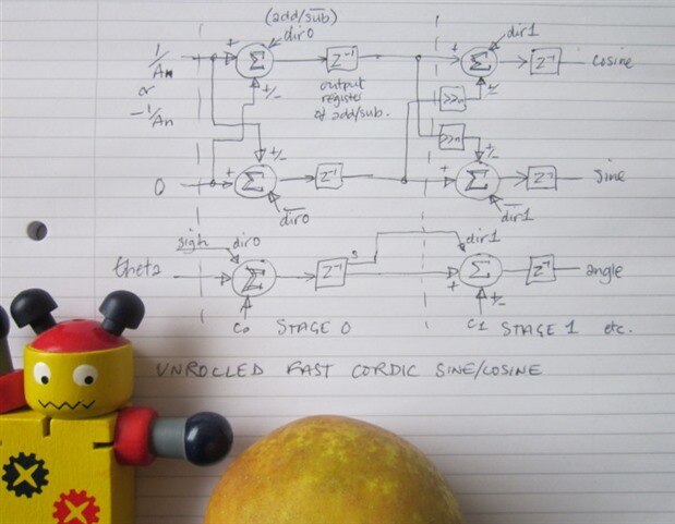
Fast CORDIC Sine
What I've done is again based on a very useful article by Ray Andraka[2] and my own experience with the bit-serial version. Here's how it looks in a fairly generic form.
(Today's apple is a D'Arcy Spice. It's a russet apple with an interesting shape, smooth firm white flesh, and a taste with a hint of tartness.)
Coding and Testing
Here's the VHDL that I pieced together. As usual, it hasn't been tested thoroughly nor had the output validated in any way. It's been slapped together as an experiment: use it for real at your peril!
------------------------------------------------------------------
--              ***** waves_cordic_fast *****                   --
-- fast CORDIC sine and cosine calculation                      --
-- pipelined, so one output sample per clock (50Msps)           --
-- this one is 6-bit resolution                                 --
-- both sine and cos are output to a 2R-R DAC                   --
-- followed by a passive filter                                 --
------------------------------------------------------------------
-- JC 22nd November 2019                                        --
------------------------------------------------------------------
-- Rev    Date         Comments                                 --
-- 01     22-Nov-2019                                           --
------------------------------------------------------------------
library ieee;
use ieee.std_logic_1164.all;
use ieee.std_logic_arith.all;
use ieee.std_logic_unsigned.all;

--- top level port that connects to the device pins
--- pin assignment is found in lpf file

entity wave_fast_cordic_con is port(
  clk_in:   in std_logic;        --- system clock in (50 MHz oscillator)
  --- DAC connections
  sin_out:  out std_logic_vector (5 downto 0);   --- sine out to DAC
  cos_out:  out std_logic_vector (5 downto 0);   --- cosine out to DAC
  --- misc control signals on evaluation board that it might be good to hold at fixed levels
  spi_cs:   out std_logic;        ---
  hold_n:   out std_logic;        ---
  sram_cen:  out std_logic;        ---
  sram_oen:  out std_logic;        ---
  sram_wen:  out std_logic;        ---
  uart_tx:  out std_logic);        ---
end wave_fast_cordic_con;

architecture arch_wave_fast_cordic of wave_fast_cordic_con is

signal start_count: std_logic_vector (1 downto 0);
signal start_reset: std_logic;
signal acc_count: std_logic_vector (7 downto 0);
signal theta: std_logic_vector (11 downto 0);
signal cos_start: std_logic_vector (11 downto 0);
signal phase_increment: std_logic_vector (31 downto 0);
signal phase_acc: std_logic_vector (31 downto 0);
signal adder_out: std_logic_vector (31 downto 0);
signal sine_value: std_logic_vector (15 downto 0);
signal cos_value: std_logic_vector (15 downto 0);
signal angle_value: std_logic_vector (15 downto 0);
signal osc_reset: std_logic_vector (1 downto 0);
signal dir_0, dir_1, dir_2, dir_3, dir_4, dir_5, dir_6, dir_7: std_logic;
signal sinA_0, sinB_0, sinR_0: std_logic_vector (11 downto 0);
signal cosA_0, cosB_0, cosR_0: std_logic_vector (11 downto 0);
signal angA_0, angB_0, angR_0: std_logic_vector (11 downto 0);
signal sinA_1, sinB_1, sinR_1: std_logic_vector (11 downto 0);
signal cosA_1, cosB_1, cosR_1: std_logic_vector (11 downto 0);
signal angA_1, angB_1, angR_1: std_logic_vector (11 downto 0);
signal sinA_2, sinB_2, sinR_2: std_logic_vector (11 downto 0);
signal cosA_2, cosB_2, cosR_2: std_logic_vector (11 downto 0);
signal angA_2, angB_2, angR_2: std_logic_vector (11 downto 0);
signal sinA_3, sinB_3, sinR_3: std_logic_vector (11 downto 0);
signal cosA_3, cosB_3, cosR_3: std_logic_vector (11 downto 0);
signal angA_3, angB_3, angR_3: std_logic_vector (11 downto 0);
signal sinA_4, sinB_4, sinR_4: std_logic_vector (11 downto 0);
signal cosA_4, cosB_4, cosR_4: std_logic_vector (11 downto 0);
signal angA_4, angB_4, angR_4: std_logic_vector (11 downto 0);
signal sinA_5, sinB_5, sinR_5: std_logic_vector (11 downto 0);
signal cosA_5, cosB_5, cosR_5: std_logic_vector (11 downto 0);
signal angA_5, angB_5, angR_5: std_logic_vector (11 downto 0);
signal sinA_6, sinB_6, sinR_6: std_logic_vector (11 downto 0);
signal cosA_6, cosB_6, cosR_6: std_logic_vector (11 downto 0);
signal angA_6, angB_6, angR_6: std_logic_vector (11 downto 0);
signal sinA_7, sinB_7, sinR_7: std_logic_vector (11 downto 0);
signal cosA_7, cosB_7, cosR_7: std_logic_vector (11 downto 0);
signal angA_7, angB_7, angR_7: std_logic_vector (11 downto 0);

--- declare the IPExpress components

component add_sub_module is
    port (
        DataA: in  std_logic_vector(11 downto 0);
        DataB: in  std_logic_vector(11 downto 0);
        Add_Sub: in  std_logic;
        Clock: in  std_logic;
        Reset: in  std_logic;
        ClockEn: in  std_logic;
        Result: out  std_logic_vector(11 downto 0));
end component;

component add_module is
    port (
        DataA: in  std_logic_vector(31 downto 0);
        DataB: in  std_logic_vector(31 downto 0);
        Result: out  std_logic_vector(31 downto 0));
end component;

begin

 wave_fast_cordic_stuff: process (clk_in)

  begin

   if (clk_in'event and clk_in='1') then
    --- Start reset
    --- Not really necessary, as it doesn't matter how
    --- it starts off; there aren't any illegal states to get
    --- stuck in

    if (start_count(1 downto 0) /= b"11") then
     start_count(1 downto 0) <= start_count(1 downto 0) + 1;
    end if;
    if (start_count(1 downto 0) = b"10") then
     start_reset <= '1';
    else
     start_reset <= '0';
    end if;

    --- phase accumulator.
    --- addition of phase increment occurs every clock.
    --- this is modulo arithmetic;  no need to test against limits
    --- as it will wrap around of its own accord

    if (start_reset = '1') then
     phase_acc(31 downto 0) <= b"00000000000000000000000000000000"; --- at start set to zero
    else
     phase_acc(31 downto 0) <= adder_out(31 downto 0);     --- store addition of increment to current phase
    end if;

    --- theta is taken from the high end of the phase accumulator.

    theta(11) <= not phase_acc(30);
    theta(10 downto 0) <= phase_acc(29 downto 19);

    --- Start value for cosine part of unit vector (sine part always starts at zero)
    --- Rather than being one, it is reciprocal of gain (1/An) through the n rounds
    --- That way, the end result for the sine and cosine is in range -1 to +1
    --- without needing a multiply afterwards to scale it.
    --- For 2nd and 3rd quadrants, need to start with the two's complement of that value
    --- [here we're starting with the unit vector pointing to 180 degrees
    ---  (cosine = -1) rather than 0 degrees (cosine = 1)]

    if (phase_acc(31) = '0') then
     cos_start(11 downto 0) <= b"0_10001100000";
    else
     cos_start(11 downto 0) <= b"1_01110100000";
    end if;

    --- Connect the output pins
    --- The outputs come from the end of the pipeline
    --- Need to complement the sign bit (DAC isn't signed)

    sin_out(5) <= not sinR_7(11);
    sin_out(4 downto 0) <= sinR_7(10 downto 6);
    cos_out(5) <= not cosR_7(11);
    cos_out(4 downto 0) <= cosR_7(10 downto 6);

   end if;

   --- various phase increments for testing

   phase_increment(31 downto 0) <= b"00110011001100110011001100110011"; --- 10MHz
---   phase_increment(31 downto 0) <= b"00000101000111101011100001010010"; --- 1MHz
---   phase_increment(31 downto 0) <= b"00000000100000110001001001101111"; --- 100kHz
---   phase_increment(31 downto 0) <= b"00001100110011001100110011001100"; --- 2.5MHz
---   phase_increment(31 downto 0) <= b"00000000110011001100110011001100"; --- 156.25kHz

   --- Wiring the stages together
   --- The barrel shift and the sign extension are done simply with wiring and don't
   --- require additional components
   --- [Might be better to create a component for a single stage that incorporates the shift
   --- wiring and the sign extensions]

   cosA_0(11 downto 0) <= cos_start(11 downto 0);
   cosB_0(11 downto 0) <= b"0_00000000000";
   sinA_0(11 downto 0) <= b"0_00000000000";
   sinB_0(11 downto 0) <= cos_start(11 downto 0);
   angA_0(11 downto 0) <= theta(11 downto 0);
   dir_0 <= theta(11);

   cosA_1(11 downto 0) <= cosR_0(11 downto 0);
   cosB_1(10 downto 0) <= sinR_0(11 downto 1);
   cosB_1(11) <= sinR_0(11);
   sinA_1(11 downto 0) <= sinR_0(11 downto 0);
   sinB_1(10 downto 0) <= cosR_0(11 downto 1);
   sinB_1(11) <= cosR_0(11);
   angA_1(11 downto 0) <= angR_0(11 downto 0);
   dir_1 <= angR_0(11);

   cosA_2(11 downto 0) <= cosR_1(11 downto 0);
   cosB_2(9 downto 0) <= sinR_1(11 downto 2);
   cosB_2(10) <= sinR_1(11);
   cosB_2(11) <= sinR_1(11);
   sinA_2(11 downto 0) <= sinR_1(11 downto 0);
   sinB_2(9 downto 0) <= cosR_1(11 downto 2);
   sinB_2(10) <= cosR_1(11);
   sinB_2(11) <= cosR_1(11);
   angA_2(11 downto 0) <= angR_1(11 downto 0);
   dir_2 <= angR_1(11);

   cosA_3(11 downto 0) <= cosR_2(11 downto 0);
   cosB_3(8 downto 0) <= sinR_2(11 downto 3);
   cosB_3(9) <= sinR_2(11);
   cosB_3(10) <= sinR_2(11);
   cosB_3(11) <= sinR_2(11);
   sinA_3(11 downto 0) <= sinR_2(11 downto 0);
   sinB_3(8 downto 0) <= cosR_2(11 downto 3);
   sinB_3(9) <= cosR_2(11);
   sinB_3(10) <= cosR_2(11);
   sinB_3(11) <= cosR_2(11);
   angA_3(11 downto 0) <= angR_2(11 downto 0);
   dir_3 <= angR_2(11);

   cosA_4(11 downto 0) <= cosR_3(11 downto 0);
   cosB_4(7 downto 0) <= sinR_3(11 downto 4);
   cosB_4(8) <= sinR_3(11);
   cosB_4(9) <= sinR_3(11);
   cosB_4(10) <= sinR_3(11);
   cosB_4(11) <= sinR_3(11);
   sinA_4(11 downto 0) <= sinR_3(11 downto 0);
   sinB_4(7 downto 0) <= cosR_3(11 downto 4);
   sinB_4(8) <= cosR_3(11);
   sinB_4(9) <= cosR_3(11);
   sinB_4(10) <= cosR_3(11);
   sinB_4(11) <= cosR_3(11);
   angA_4(11 downto 0) <= angR_3(11 downto 0);
   dir_4 <= angR_3(11);

   cosA_5(11 downto 0) <= cosR_4(11 downto 0);
   cosB_5(6 downto 0) <= sinR_4(11 downto 5);
   cosB_5(7) <= sinR_4(11);
   cosB_5(8) <= sinR_4(11);
   cosB_5(9) <= sinR_4(11);
   cosB_5(10) <= sinR_4(11);
   cosB_5(11) <= sinR_4(11);
   sinA_5(11 downto 0) <= sinR_4(11 downto 0);
   sinB_5(6 downto 0) <= cosR_4(11 downto 5);
   sinB_5(7) <= cosR_4(11);
   sinB_5(8) <= cosR_4(11);
   sinB_5(9) <= cosR_4(11);
   sinB_5(10) <= cosR_4(11);
   sinB_5(11) <= cosR_4(11);
   angA_5(11 downto 0) <= angR_4(11 downto 0);
   dir_5 <= angR_4(11);

   cosA_6(11 downto 0) <= cosR_5(11 downto 0);
   cosB_6(5 downto 0) <= sinR_5(11 downto 6);
   cosB_6(6) <= sinR_5(11);
   cosB_6(7) <= sinR_5(11);
   cosB_6(8) <= sinR_5(11);
   cosB_6(9) <= sinR_5(11);
   cosB_6(10) <= sinR_5(11);
   cosB_6(11) <= sinR_5(11);
   sinA_6(11 downto 0) <= sinR_5(11 downto 0);
   sinB_6(5 downto 0) <= cosR_5(11 downto 6);
   sinB_6(6) <= cosR_5(11);
   sinB_6(7) <= cosR_5(11);
   sinB_6(8) <= cosR_5(11);
   sinB_6(9) <= cosR_5(11);
   sinB_6(10) <= cosR_5(11);
   sinB_6(11) <= cosR_5(11);
   angA_6(11 downto 0) <= angR_5(11 downto 0);
   dir_6 <= angR_5(11);

   cosA_7(11 downto 0) <= cosR_6(11 downto 0);
   cosB_7(4 downto 0) <= sinR_6(11 downto 7);
   cosB_7(5) <= sinR_6(11);
   cosB_7(6) <= sinR_6(11);
   cosB_7(7) <= sinR_6(11);
   cosB_7(8) <= sinR_6(11);
   cosB_7(9) <= sinR_6(11);
   cosB_7(10) <= sinR_6(11);
   cosB_7(11) <= sinR_6(11);
   sinA_7(11 downto 0) <= sinR_6(11 downto 0);
   sinB_7(4 downto 0) <= cosR_6(11 downto 7);
   sinB_7(5) <= cosR_6(11);
   sinB_7(6) <= cosR_6(11);
   sinB_7(7) <= cosR_6(11);
   sinB_7(8) <= cosR_6(11);
   sinB_7(9) <= cosR_6(11);
   sinB_7(10) <= cosR_6(11);
   sinB_7(11) <= cosR_6(11);
   angA_7(11 downto 0) <= angR_6(11 downto 0);
   dir_7 <= angR_6(11);

---   sin_out(5) <= not theta(11);    --- for testing the phase value given to the CORDIC processor
---   sin_out(4 downto 0) <= theta(10 downto 6);

   --- Hold these device control pins at a fixed level to stop them flapping around

   spi_cs <= '1';
   hold_n <= '1';
   sram_cen <= '1';
   sram_oen <= '1';
   sram_wen <= '1';
   uart_tx <= '1';

  end process wave_fast_cordic_stuff;

  --- Instantiate the adder-subtractors
  --- The CORDIC inverse-tangent constant for each stage is just direct wiring to the DataB input of
  --- the angle add/sub module

  --- stage 0

  add_sub_sine_0: add_sub_module
   port map(DataA => sinA_0(11 downto 0), DataB => sinB_0(11 downto 0), Add_Sub => not dir_0,
            Clock => clk_in, Reset => start_reset, ClockEn => '1', Result => sinR_0(11 downto 0));
  add_sub_cos_0: add_sub_module
   port map(DataA => cosA_0(11 downto 0), DataB => cosB_0(11 downto 0), Add_Sub => dir_0,
            Clock => clk_in, Reset => start_reset, ClockEn => '1', Result => cosR_0(11 downto 0));
  add_sub_angle_0: add_sub_module
   port map(DataA => angA_0(11 downto 0), DataB => b"010000011001", Add_Sub => dir_0,
            Clock => clk_in, Reset => start_reset, ClockEn => '1', Result => angR_0(11 downto 0));

  --- stage 1

  add_sub_sine_1: add_sub_module
   port map(DataA => sinA_1(11 downto 0), DataB => sinB_1(11 downto 0), Add_Sub => not dir_1,
           Clock => clk_in, Reset => start_reset, ClockEn => '1', Result => sinR_1(11 downto 0));
  add_sub_cos_1: add_sub_module
   port map(DataA => cosA_1(11 downto 0), DataB => cosB_1(11 downto 0), Add_Sub => dir_1,
           Clock => clk_in, Reset => start_reset, ClockEn => '1', Result => cosR_1(11 downto 0));
  add_sub_angle_1: add_sub_module
   port map(DataA => angA_1(11 downto 0), DataB => b"001001101011", Add_Sub => dir_1,
            Clock => clk_in, Reset => start_reset, ClockEn => '1', Result => angR_1(11 downto 0));

  --- stage 2

  add_sub_sine_2: add_sub_module
   port map(DataA => sinA_2(11 downto 0), DataB => sinB_2(11 downto 0), Add_Sub => not dir_2,
           Clock => clk_in, Reset => start_reset, ClockEn => '1', Result => sinR_2(11 downto 0));
  add_sub_cos_2: add_sub_module
   port map(DataA => cosA_2(11 downto 0), DataB => cosB_2(11 downto 0), Add_Sub => dir_2,
           Clock => clk_in, Reset => start_reset, ClockEn => '1', Result => cosR_2(11 downto 0));
  add_sub_angle_2: add_sub_module
   port map(DataA => angA_2(11 downto 0), DataB => b"000101000111", Add_Sub => dir_2,
            Clock => clk_in, Reset => start_reset, ClockEn => '1', Result => angR_2(11 downto 0));

  --- stage 3

  add_sub_sine_3: add_sub_module
   port map(DataA => sinA_3(11 downto 0), DataB => sinB_3(11 downto 0), Add_Sub => not dir_3,
            Clock => clk_in, Reset => start_reset, ClockEn => '1', Result => sinR_3(11 downto 0));
  add_sub_cos_3: add_sub_module
   port map(DataA => cosA_3(11 downto 0), DataB => cosB_3(11 downto 0), Add_Sub => dir_3,
           Clock => clk_in, Reset => start_reset, ClockEn => '1', Result => cosR_3(11 downto 0));
  add_sub_angle_3: add_sub_module
   port map(DataA => angA_3(11 downto 0), DataB => b"000010100110", Add_Sub => dir_3,
           Clock => clk_in, Reset => start_reset, ClockEn => '1', Result => angR_3(11 downto 0));

  --- stage 4

  add_sub_sine_4: add_sub_module
   port map(DataA => sinA_4(11 downto 0), DataB => sinB_4(11 downto 0), Add_Sub => not dir_4,
           Clock => clk_in, Reset => start_reset, ClockEn => '1', Result => sinR_4(11 downto 0));
  add_sub_cos_4: add_sub_module
   port map(DataA => cosA_4(11 downto 0), DataB => cosB_4(11 downto 0), Add_Sub => dir_4,
           Clock => clk_in, Reset => start_reset, ClockEn => '1', Result => cosR_4(11 downto 0));
  add_sub_angle_4: add_sub_module
   port map(DataA => angA_4(11 downto 0), DataB => b"000001010011", Add_Sub => dir_4,
           Clock => clk_in, Reset => start_reset, ClockEn => '1', Result => angR_4(11 downto 0));

  --- stage 5

  add_sub_sine_5: add_sub_module
   port map(DataA => sinA_5(11 downto 0), DataB => sinB_5(11 downto 0), Add_Sub => not dir_5,
           Clock => clk_in, Reset => start_reset, ClockEn => '1', Result => sinR_5(11 downto 0));
  add_sub_cos_5: add_sub_module
   port map( DataA => cosA_5(11 downto 0), DataB => cosB_5(11 downto 0), Add_Sub => dir_5,
           Clock => clk_in, Reset => start_reset, ClockEn => '1', Result => cosR_5(11 downto 0));
  add_sub_angle_5: add_sub_module
   port map(DataA => angA_5(11 downto 0), DataB => b"000000101010", Add_Sub => dir_5,
           Clock => clk_in, Reset => start_reset, ClockEn => '1', Result => angR_5(11 downto 0));

  --- stage 6

  add_sub_sine_6: add_sub_module
   port map(DataA => sinA_6(11 downto 0), DataB => sinB_6(11 downto 0), Add_Sub => not dir_6,
           Clock => clk_in, Reset => start_reset, ClockEn => '1', Result => sinR_6(11 downto 0));
  add_sub_cos_6: add_sub_module
   port map(DataA => cosA_6(11 downto 0), DataB => cosB_6(11 downto 0), Add_Sub => dir_6,
           Clock => clk_in, Reset => start_reset, ClockEn => '1', Result => cosR_6(11 downto 0));
  add_sub_angle_6: add_sub_module
   port map(DataA => angA_6(11 downto 0), DataB => b"000000010101", Add_Sub => dir_6,
            Clock => clk_in, Reset => start_reset, ClockEn => '1', Result => angR_6(11 downto 0));

  --- stage 7

  add_sub_sine_7: add_sub_module
   port map(DataA => sinA_7(11 downto 0), DataB => sinB_7(11 downto 0), Add_Sub => not dir_7,
            Clock => clk_in, Reset => start_reset, ClockEn => '1', Result => sinR_7(11 downto 0));
  add_sub_cos_7: add_sub_module
   port map(DataA => cosA_7(11 downto 0), DataB => cosB_7(11 downto 0), Add_Sub => dir_7,
           Clock => clk_in, Reset => start_reset, ClockEn => '1', Result => cosR_7(11 downto 0));
  add_sub_angle_7: add_sub_module
   port map(DataA => angA_7(11 downto 0), DataB => b"000000001010", Add_Sub => dir_7,
           Clock => clk_in, Reset => start_reset, ClockEn => '1', Result => angR_7(11 downto 0));

  --- instantiate the phase adder

  add_1: add_module  --- phase accumulator calculation
   port map(
    DataA => phase_acc(31 downto 0),
    DataB => phase_increment(31 downto 0),
    Result => adder_out(31 downto 0));
end arch_wave_fast_cordic;
The components I used IPExpress for were:
This time there's no need for the ROM table. The inverse tangents of the sine/cos multipliers [0.5, 0.25, 0.125, ...] for each stage, represented in the number format I chose for the arithmetic, are simply hard-wired to the adder inputs. As I did in blog 6, these have been adjusted [scaled] so that the angle works over the interval -1 to +1, rather than -pi/2 to +pi/2 in order to avoid having to scale the angle value obtained from the phase accumulator [scaling the value from the accumulator would take a multiplier whereas scaling the constants is a one-time operation that I did with a calculator].
There's also no need for a barrel shifter made from components. The shift for a particular stage is constant and can be accomplished by how we wire up the adders, as can the sign extension that becomes necessary with a two's complement representation.
In blog 6, I obtained the second and third quadrants of the sinewave by manipulating the theta value. In numerical terms, that meant the angle value went from 0 to +1, back through 0 to -1 and then returned to 0 [in terms of degrees, from 0 to 90, then back to -90 and finally 0 again]. Whilst that did work to get the full cycle of the sinewave, it doesn't properly give the cosine - the cosine remains positive the whole time. This time I wanted to display the cosine and sine at the same time, to show the quadrature relationship between them, so I needed to come up with a different approach. One way to do that would be to generate the waveforms over a limited range of angles and then manipulate the results, using the two symmetries of the waveforms, to get the rest. But that's quite a fiddly bit of pre- and post-processing to do, so, instead, I decided to try simply changing the start vector for one half of the cycle to point at 180 degrees rather than 0 degrees [the vector I'm referring to is the one that the current cos/sine pair represents and that gets rotated in step with the angle processing]. That does seem to work, though it looks like I may have a small problem where the sine passes through zero [this is experimentation, so still 'work in progress', and there are other possibilities for a glitch at that point]. I thought I might need to manipulate the way the decisions to add or subtract were done as well, but that wasn't necessary. In the end it turned out to be much simpler than what I had before.
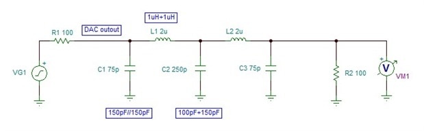
DAC and Reconstruction Filter
This is the circuit of the DAC and of the reconstruction filter.
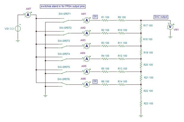
For the DAC, I decided to go with fairly low resistor values. It would have been nice to work 50 ohms [it's kind of a tradition for rf stuff, isn't it], but the FPGA pins aren't up to that, so I went for 100. That's still a bit on the low side, and it's enough of a load to pull the output pins away from the rails so the output levels aren't as accurate as they might be, but it's good enough for the moment for messing about with.
The filter has a 5th-order Butterworth response and I designed it in the same way as before. The cut-off frequency is around 12.8MHz. One thing that won't be too obvious is that the resistor that normally sits at the input of the filter for this particular configuration has been replaced by the effective resistance value looking back into the output of the resistor network (100R).
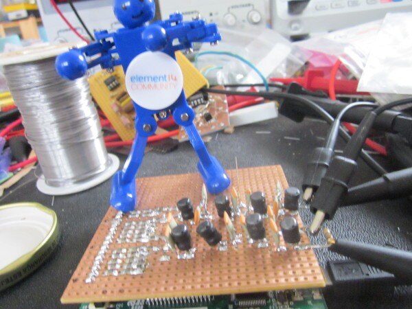
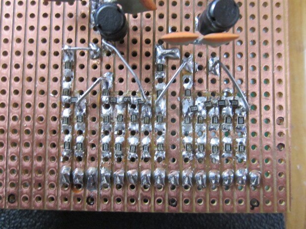
For the build, I used surface-mount resistors (0805, 1% parts) on a piece of stripboard and, in order to use components that I had to hand, I wired two 1uH inductors in series to get the 2uH that I wanted, two 150pF capacitors in series for 75pF, and a 100pF and a 150pF in parallel for 250pF. The coils are small, radial power inductors from Wurth. I wasn't very sure about using them in place of an rf choke (the srf is much better than I would have expected, up around something like 150MHz, but there's no information on the datasheet about other properties). Unfortunately, I don't have the test equipment to measure how they behave at high frequency. I tried to space the coils apart, as they are only semi-screened by the shaped core, but there's probably some coupling between them.
A close-up of the DAC resistors
Testing
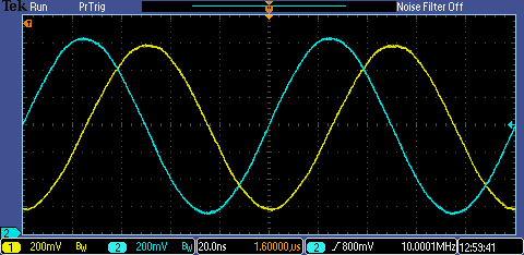
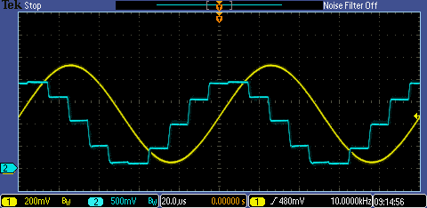
Here it is generating 100kHz sine and cosine waveforms. Because of the low resolution of the DAC, we can see the steps clearly.
I'm not sure about the glitch at zero on the sine. It looks like the two halves don't quite join up, so needs more investigation.
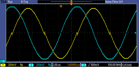
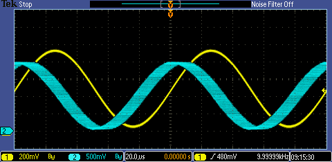
Here is 1MHz
That isn't too steady. It's also lumpy, so the samples aren't quite in the right places. You can't see it in these static shots, but there's a rippling effect to the lumpiness running through the waveform that is so slow that it can only be driven by the steady change in the phase accumulator because of the slight inaccuracy of the arithmetic.
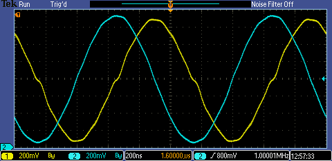
Finally, here is 10MHz, which is pushing the boat out a bit but does work, though at a reduced amplitude
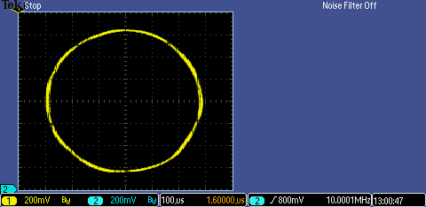
That last one was better than I expected. The two filters, which should be identical, obviously aren't, but the general waveshape is a lot better because it's coming from the filter reconstructing just a few samples rather than being forced by the DAC all the time. Because the two outputs, sine and cosine, represent a rotating vector, if I get the oscilloscope to plot them XY I should get back to a circle and I do. Sort of.
Update 27 November 2019
I was a bit concerned about the less than stable sinewaves I was getting above and the glitch at the zero level with the slow one so I decided to swap daughterboards and try the fast CORDIC code with the SPI DAC. Although the resolution will still be 6 bits, padded with zeroes for the lower bits, the SPI DAC's output will be far more precise in level and the slewing will be a smaller proportion of the sample interval.
For that to work, I needed to slow down the generation of the samples. The registered outputs for each stage will take a clock enable so I simply generated an enable that lasts for one clock period every 10uS and that resulted in an output at the 100ksps that I used previously with the SPI part. A quick bit of hacking to put back the code to send the result over the SPI bus and I'm there.
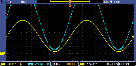
Here's the equivalent of the slow waveform that showed the glitch, it's now 200Hz and there's no sign of the odd behaviour at the zero crossing (the blue trace is the output of the DAC and the yellow trace the output of the filter).
Here's the equivalent of the faster one that showed the bulge at the side
Now it's a much more reasonable shape. There is though some variation to the amplitude of the yellow trace as the phase slowly changes [I've got the phase increment set so that it's slightly off of being an integer divisor of a complete cycle].
Here it is on a long persistence, where we can see the path traced by the tops of the samples
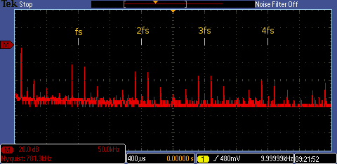
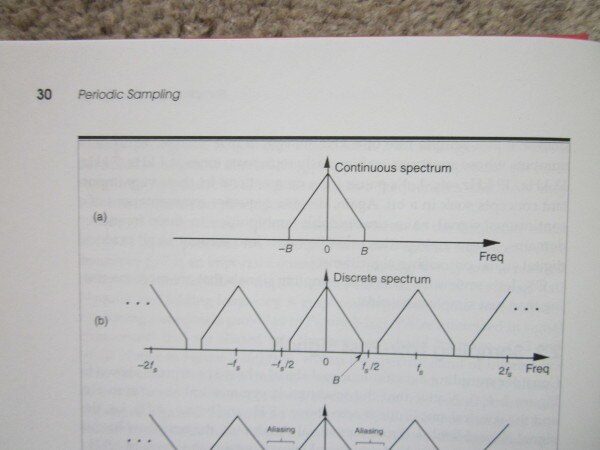
On a slightly different note, I did an FFT of the DAC output (the stepped waveform) and it came out like this. I've annotated it with the sampling frequency and its multiples. That shows the images of the waveform I'm generating that appear below and above each multiple of the sampling frequency.
In a textbook [3], it would get shown like this:
That's for a sampled continuous input signal but, when we generate our samples, we're doing the same thing virtually within the arithmetic: taking a continuous function, sampling it at intervals and, if we get it right, producing the same output that would have occurred if the sinewave had been input and sampled rather than generated.
Conclusion
This is good fun. I'm gradually getting a better feel for the CORDIC processor and the way it operates, and there's a real sense of achievement figuring some of it out for myself rather than just cloning what someone else has done.
[1] http://www.latticesemi.com/en/Products/DevelopmentBoardsAndKits/LatticeXP2Brevia2DevelopmentKit.aspx [2] http://www.andraka.com/files/crdcsrvy.pdf |
Top Comments