


RTL Combinational Circuit - Design Examples - Barrel Shifter RTL Combinational Circuit
We continue experimenting with RTL Combinational Circuits designed in SystemVerilog. In this blog we are going to design circuits around a very useful circuit that is present in many designs, the barrel shifter circuit. We will start with the simplest ways to implement a single-direction rotation barrel shifter for fixed-bit-width words and finish by designing a multi-function dual-direction barrel shifter circuit with parameterizable word width.
Table of Contents
-
- Barrel Shifter
- Simple 8-bit right rotator
- Simple staged 8-bit right rotator
- Multi-function barrel shifter. Rotating right or left.
- Multi-function 8-bit barrel shifter with pre and post reversing circuits
- Multi-function 32-bit barrel shifter with pre and post reversing circuits
- Multi-function 32-bit barrel shifter with left shifter and right shifter multiplexing
- Parameterizable word width multifunction barrel shifter
- Testing circuit with the Arty S7
- The barrel shifter in action
- SystemVerilog Study Notes Chapters
SystemVerilog Study Notes Chapters
- Gate-Level Combinational Circuit
- RTL Combinational Circuit Operators
- RTL Combinational Circuit - Concurrent and Control Constructs
- Hex-Digit to Seven-Segment LED Decoder RTL Combinational Circuit
- Barrel Shifter RTL Combinational Circuit
- Simplified Floating Point Arithmetic. RTL Combinational Circuit
- BCD Number Format. RTL Combinational Circuit
- DDFS. Direct Digital Frequency Synthesis for Sound
- FPGA ADSR envelope generator for sound synthesis
- AMD Xilinx 7 series FPGAs XADC
- Building FPGA-Based Music Instrument Synthesis: A Simple Test Bench Solution
Barrel Shifter
A barrel shifter is a digital circuit that can shift a data word by a specified number of bits without the use of any sequential logic, only pure combinational logic. Its has a control input that specifies the number of bit positions that it shifts by. The Barrel Shifter is similar to the Shift Register (Multi-bit), except that bits shifted of the register are shifted back into the opposite end of the register. For example, in right shift operations, the LSBs shifted out of the register are shifted into the MSBs.
Barrel shifters are applicable for digital signal processors and processors.
One way to implement a barrel shifter is as a sequence of multiplexers where the output of one multiplexer is connected to the input of the next multiplexer in a way that depends on the shift distance. When implementing a barrel shifter with a sequence of shift multiplexers, each shifts a word by 2^k bit positions (1,2,4,8,16,32...) for different values of k. The number of multiplexing stages is relative to the width of the input vector.
The diagram below shows a right-shifting barrel shifter for 32-bit words.

With more complex multiplexers and some extra circuitry for dealing with end fill options, a barrel shifter can handle all of the standard bit shift instruction in a processor's instruction set.
Simple 8-bit right rotator
We start with the simplest and most direct way to program a right-shift barrel shifter in Verilog HDL, using a case statement with all possible rotation combinations.
We will design a simple 8-bit barrel shifter that rotates and arbitrary number of bits to the right. The circuit has an 8-bit data input, data, and a 3-bit control signal, amt, which specifies the amount to be rotated.
The design uses a selected signal assignment statement to exhaustively list all the combinations of the amt signal and the corresponding rotated results.
SystemVerilog implementation using a case statement
`timescale 1ns / 10ps

module barrel_shifter_built_case(
    input logic [7:0] data,
    input logic [2:0] amt,
    output logic [7:0] out
);

    always_comb
    begin
        case (amt)
            3'o0: out = data;
            3'o1: out = {data[0], data[7:1]};
            3'o2: out = {data[1:0], data[7:2]};
            3'o3: out = {data[2:0], data[7:3]};
            3'o4: out = {data[3:0], data[7:4]};
            3'o5: out = {data[4:0], data[7:5]};
            3'o6: out = {data[5:0], data[7:6]};
            default  out = {data[6:0], data[7]};
        endcase
    end
endmodule
Test bench and simulation
The test bench uses a for loop to iterate through all possibilities of the signal indicating the amount to rotate.
`timescale 1ns / 10ps

module barrel_shifter_built_case_testbench;
    logic [7:0] data;
    logic [2:0] amt;
    logic [7:0] out;

    barrel_shifter_built_case uut(.*);

    initial begin
        for (byte i = 0; i < 8; ++i)
            begin
                data = 8'b1111_0000; amt = 3'(i); #10;
            end
        $stop;
    end

endmodule
In the image of the scope you can see how the values are shifted to the right amt bits, towards the LSB bits and how the MSBs are filled with the overflowing bits, rotating the information from left to right.

RTL Elaborated Design Schematics
This way of designing the barrel shifter implies the use of a wide 3 to 8 multiplexer

The code is straightforward but implies a wide multiplexer, which makes synthesis difficult and leads to a large propagation delays.
If the number of input bits increases it will be cumbersome.
Synthesized Design Schematic

Simple staged 8-bit right rotator
Alternatively, we can construct the circuit by stages. In the nth stage, the input signal is either passed directly to output or rotated right by 2^n positions. The nth stage is controlled by the nth bit of the amt signal.
If {am2, am1, am0} are the 3 bits of amt signal the total rotated amount after three stages is am2 * 2^2 + am1 * 2 + am0, which is the desired rotating amount.
`timescale 1ns / 10ps

module barrel_shifter_staged(
    input logic [7:0] data,
    input logic [2:0] amt,
    output logic [7:0] out
);

    logic [7:0] stage0;
    logic [7:0] stage1;

    always_comb
    begin
        //stage 0, shift 0 or 1 bit
        if(amt[0]) begin
            stage0 = {data[0], data[7:1]};
        end else
            begin
                stage0 = data;
            end

        //stage 1, shift 0 or 2 bits
        if(amt[1]) begin
            stage1 = {stage0[1:0], stage0[7:2]};
        end else
            begin
                stage1 = stage0;
            end

        //stage 2, shift 0 or 4 bits
        if(amt[2]) begin
            out = {stage1[3:0], stage1[7:4]};
        end else
            begin
                out = stage1;
            end
    end

endmodule
Or more compact but not more clearer using the "?:" ternary expression.
module barrel_shifter_staged(
    input logic [7:0] data,
    input logic [2:0] amt,
    output logic [7:0] out
);

    logic [7:0] s0;
    logic [7:0] s1;

    assign s0  = amt[0]? {data[0], data[7:1]} :data ;
    assign s1  = amt[1]? {s0[1:0], s0[7:2]} :s0 ;
    assign out = amt[2]? {s1[3:0], s1[7:4]} :s1;
endmodule
The circuit now uses a series of 2 to 1 multiplexors


Multi-function barrel shifter. Rotating right or left.
We are going to complicate our barrel shifter a bit by adding a new signal that allows us to control the direction of the shift of the bits. With this signal we can tell the barrel shifter circuit if we want the output with the bits shifted an amount of bits to the right or to the left.
This 8-bit shifting circuit that can perform a rotating-right a rotating-left operation. An additional 1-bit control signal, dir_lr, specifies the desired direction.
First we will design the circuit using one rotate-right circuit, one rotate-left circuit and 2-to1 multiplexer to select the desired result.
A possible SystemVerilog implementation
`timescale 1ns / 10ps
const logic ROTATE_LEFT = 1'b1;
const logic ROTATE_RIGHT = 1'b0;

module barrel_shifter_multifunction(
    input logic [7:0] data,
    input logic [2:0] amt,
    input logic dir_lr, // 1 rotate left, 0 rotate right
    output logic [7:0] out
);
    logic [7:0] outl;
    logic [7:0] outr;
    barrel_shifter_right bsr(.*, .out(outr));
    barrel_shifter_left bsl(.*, .out(outl));

    assign out = dir_lr == ROTATE_LEFT ? outl:outr;

endmodule

// rotates amt bits of data to the right
module barrel_shifter_right(
    input logic [7:0] data,
    input logic [2:0] amt,
    output logic [7:0] out
);

    logic [7:0] s0;
    logic [7:0] s1;
    //stage 0, shift 0 or 1 bit
    assign s0 =  amt[0]? {data[0], data[7:1]} :data ;
    //stage 1, shift 0 or 2 bits
    assign s1 =  amt[1]? {s0[1:0], s0[7:2]} :s0 ;
    //stage 1, shift 0 or 4 bits
    assign out = amt[2]?{s1[3:0], s1[7:4]} :s1;
endmodule

// rotates amt bits of data to the left
module barrel_shifter_left(
    input logic [7:0] data,
    input logic [2:0] amt,
    output logic [7:0] out
);

    logic [7:0] s0;
    logic [7:0] s1;
    //stage 0, shift 0 or 1 bit
    assign s0 = amt[0]? { data[6:0], data[7]} :data ;
    //stage 1, shift 0 or 2 bits
    assign s1 = amt[1]? { s0[5:0], s0[7:6]} :s0 ;
    //stage 1, shift 0 or 4 bits
    assign out = amt[2]?{s1[3:0], s1[7:4]} :s1;
endmodule
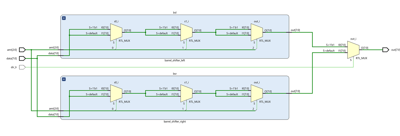
The code includes two 8-bit rotating shifters, one to the right and one to the left. Using a 1 to 2 multiplexer, the output of one of the shifters is selected.

The two expanded shifters, each shifter has 3, 1-to-2 multiplexers for each of the stages required for the 3-bit shift amount signal.
Test-bench and simulation
The test-bench code loops through all possible shift amount possibilities for the two possible shift cases, left and right.
module barrel_shifter_multifunction_testbench;
    logic [7:0] data;
    logic [2:0] amt;
    logic [7:0] out;
    logic dir_lr;

    barrel_shifter_multifunction uut(.*);

    initial begin
        assign dir_lr = ROTATE_LEFT;
        for (byte i = 0; i < 8; ++i)
            begin
                data = 8'b1111_0000; amt = 3'(i); #10;
            end
        assign dir_lr = ROTATE_RIGHT;
        for (byte i = 0; i < 8; ++i)
            begin
                data = 8'b1111_0000; amt = 3'(i); #10;
            end
        $stop;
    end
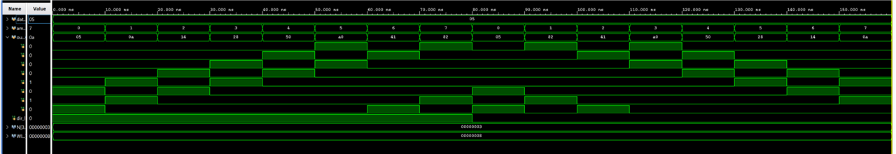
Simulation
The scope view first shows us all the left shift cases and then all the right shift cases for the original string 8'b1111_0000

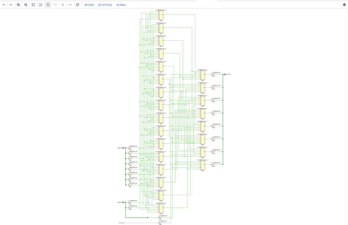
The synthetized design uses 44 cells
Multi-function 8-bit barrel shifter with pre and post reversing circuits
This circuit can also be implemented by one rotate shifter with pre- and post reversing circuits, so the basic multiplexing function can perform both operations. The reversing circuit either passes the original input or reverses the input bitwise.
`timescale 1ns / 10ps
const logic ROTATE_LEFT = 1'b1;
const logic ROTATE_RIGHT = 1'b0;

// Barrel Shifter using a Rotate-right-shifter with pre- and post-reversing circuits
module barrel_shifter_multi_rev(
    input logic [7:0] data,
    input logic [2:0] amt,
    input logic dir_lr, // 1 rotate left, 0 rotate right
    output logic [7:0] out
);
    logic [7:0] out_right; // output result
    logic [7:0] reversed_outr; // reversed output rotation for right rotation
    logic [7:0] reversed_data; // reversed input data for left rotation

    // if rotate left use rotated input data
    barrel_shifter_8_right bsr(.data((dir_lr == ROTATE_LEFT) ? reversed_data:data), .amt(amt) , .out(out_right));
    // reverse input circuit
    inverter_8 input_inverter(.data(data), .out(reversed_data));
    //  reverse output circuit
    inverter_8 output_inverter(.data(out_right), .out(reversed_outr));

     // if rotate right use rotated output
    assign  out = (dir_lr == ROTATE_LEFT) ? reversed_outr:out_right;

endmodule

// reverse 8-bit data
module inverter_8(
    input logic [7:0] data,
    output logic [7:0] out
);
// reverse a vector using right-to-left streaming with the default block size of 1 bit
  assign out = {<<{data}};
endmodule
// rotates amt bits of data to the right
module barrel_shifter_8_right(
    input logic [7:0] data,
    input logic [2:0] amt,
    output logic [7:0] out
);

    logic [7:0] s0;
    logic [7:0] s1;
    //stage 0, shift 0 or 1 bit
    assign s0 =  amt[0]? {data[0], data[7:1]} :data ;
    //stage 1, shift 0 or 2 bits
    assign s1 =  amt[1]? {s0[1:0], s0[7:2]} :s0 ;
    //stage 1, shift 0 or 4 bits
    assign out = amt[2]?{s1[3:0], s1[7:4]} :s1;
endmodule
To reverse the date we use right-to-left streaming with the default block size of 1 bit: assign out = {<<{data}};
Test bench
We use the same test-bench as in the previous case.
`timescale 1ns / 10ps

module barrel_shifter_multi_rev_testbench;
    logic [7:0] data;
    logic [2:0] amt;
    logic [7:0] out;
    logic dir_lr;

    barrel_shifter_multi_rev uut(.*);

    initial begin
        assign dir_lr = ROTATE_LEFT;
        for (byte i = 0; i < 8; ++i)
            begin
                data = 8'b0000_0001; amt = 3'(i); #10;
            end
        assign dir_lr = ROTATE_RIGHT;
        for (byte i = 0; i < 8; ++i)
            begin
                data = 8'b0000_0001; amt = 3'(i); #10;
            end
        $stop;
    end

endmodule
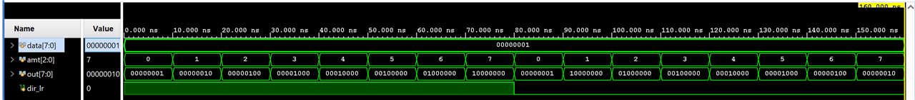
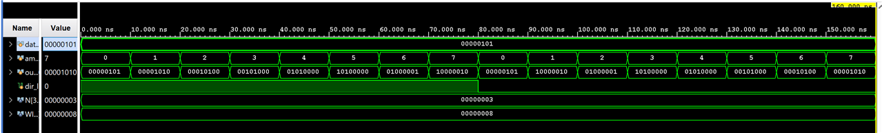
Simulation
We do the simulation in this case with the string 8'b0000_0001
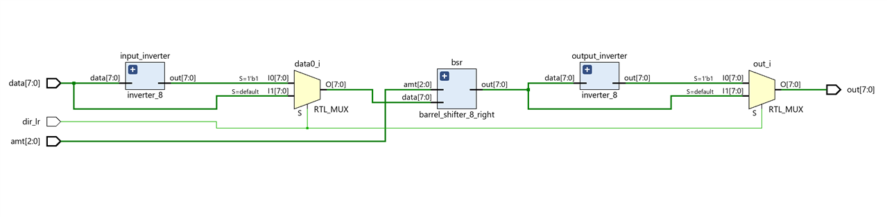
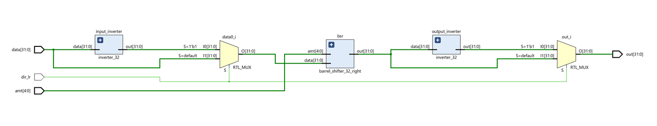
In the schematic of the elaborated design we can observe the two reversing circuits that invert the position of the bits both at the input and at the output. The two multiplexers that select the non-inverted or inverted output input based on the shift direction and the right shift circuit. Only a single shifter circuit is needed in this case.
The synthetized design uses 44 cells.
Multi-function 32-bit barrel shifter with pre and post reversing circuits
We are going to extend the previous circuit to be able to work with words that are 32 bits long.
`timescale 1ns / 10ps
const logic ROTATE_LEFT = 1'b1;
const logic ROTATE_RIGHT = 1'b0;

module barrel_shifter_32_multi_rev(
    input logic [31:0] data,
    input logic [4:0] amt,
    input logic dir_lr, // 1 rotate left, 0 rotate right
    output logic [31:0] out
);
    logic [31:0] out_right;
    logic [31:0] reversed_outr;
    logic [31:0] reversed_data;

    barrel_shifter_32_right bsr(.data((dir_lr == ROTATE_LEFT) ? reversed_data:data), .amt(amt) , .out(out_right));

     // reverse input circuit
    inverter_32 input_inverter(.data(data), .out(reversed_data));
    //  reverse output circuit
    inverter_32 output_inverter(.data(out_right), .out(reversed_outr));

     // if rotate right use rotated output
    assign  out = (dir_lr == ROTATE_LEFT) ? reversed_outr:out_right;

endmodule

// rotates amt bits of data to the right
module barrel_shifter_32_right(
    input logic [31:0] data,
    input logic [4:0] amt,
    output logic [31:0] out
);

    logic [31:0] s0;
    logic [31:0] s1;
    logic [31:0] s2;
    logic [31:0] s3;

    //stage 0, shift 0 or 1 bit
    assign s0 =  amt[0]? {data[0], data[31:1]} :data ;
    //stage 1, shift 0 or 2 bits
    assign s1 =  amt[1]? {s0[1:0], s0[31:2]} :s0 ;
    //stage 2, shift 0 or 4 bits
    assign s2 = amt[2]?{s1[3:0], s1[31:4]} :s1;
    //stage 3, shift 0 or 8 bits
    assign s3 = amt[3]?{s2[7:0], s2[31:8]} :s2;
    //stage 4, shift 0 or 16 bits
    assign out = amt[4]?{s3[15:0], s3[31:16]} :s3;

endmodule

// reverse 32-bit data
module inverter_32(
    input logic [31:0] data,
    output logic [31:0] out
);
// reverse a vector using right-to-left streaming with the default block size of 1 bit
  assign out = {<<{data}};
endmodule
The main change affects the lengths of the data signals as well as the signal that indicates the amount to be shifted. In this case for 32 bits our shift signal has to be 5 bits long to loop to all cases.
The shift right circuit is also changed and we have to add new shift stages to get up to the 5 required stages.
Test bench
The test bench must also be adapted to the new sizes.
`timescale 1ns / 10ps
module barrel_shifter_32_multi_rev_testbench;
    logic [31:0] data;
    logic [4:0] amt;
    logic [31:0] out;
    logic dir_lr;

    barrel_shifter_32_multi_rev uut(.*);

    initial begin
        for (int i = 0; i < 32; ++i)
            begin
                data = 32'b1; amt = i; dir_lr = ROTATE_LEFT; #10;
            end
        for (int i = 0; i < 32; ++i)
            begin
                data = 32'b1; amt =i; dir_lr = ROTATE_RIGHT;  #10;
            end
        $stop;
    end

endmodule
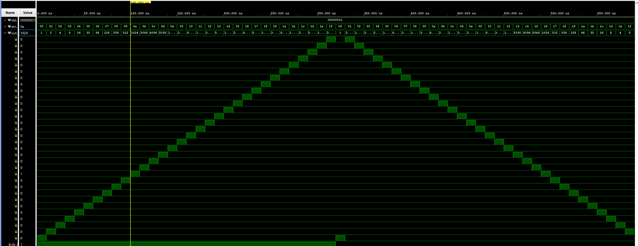
Simulation
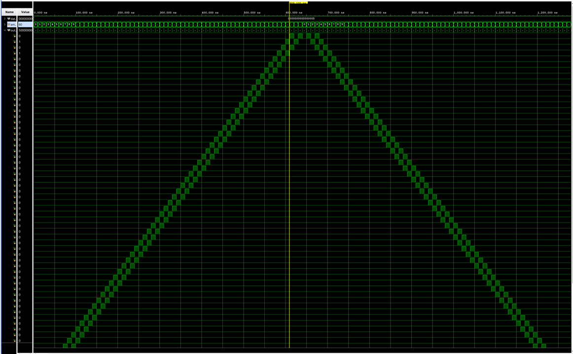
We do the simulation in this case with the string 32'b0000_0000_0000_0000_0000_0000_0000_0001

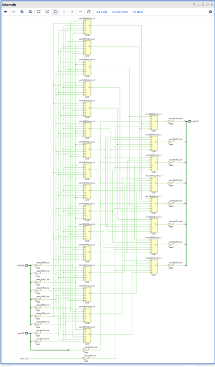
The scheme of the elaborated design is similar to the one elaborated for 8-bits we see that the sizes of the data buses change, they have been enlarged to the new sizes.
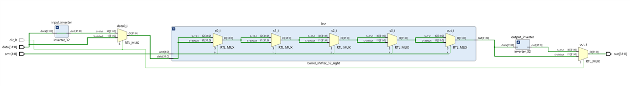
Expanding the barrel shifter block we see that the number of multiplexers has increased due to the new shifting stages required.
The synthesized design is getting more complicated.

Multi-function 32-bit barrel shifter with left shifter and right shifter multiplexing
We can perform the same exercise as before with 32-bit lengths but in this case, instead of using pre- and post reversing circuits, we use two barrel shifters, one to the right and one to the left selectable by means of another multiplexer.
`timescale 1ns / 10ps
const logic ROTATE_LEFT = 1'b1;
const logic ROTATE_RIGHT = 1'b0;

module barrel_shifter_32_multi(
    input logic [31:0] data,
    input logic [4:0] amt,
    input logic dir_lr, // 1 rotate left, 0 rotate right
    output logic [31:0] out
);
    logic [31:0] out_right;
    logic [31:0] out_left;


    barrel_shifter_32_right bsr(.data(data), .amt(amt) , .out(out_right));
    barrel_shifter_32_left bsl(.data(data), .amt(amt) , .out(out_left));

     // if rotate right use rotated output
    assign  out = (dir_lr == ROTATE_LEFT) ? out_left:out_right;

endmodule

// rotates amt bits of data to the right
module barrel_shifter_32_right(
    input logic [31:0] data,
    input logic [4:0] amt,
    output logic [31:0] out
);

    logic [31:0] s0;
    logic [31:0] s1;
    logic [31:0] s2;
    logic [31:0] s3;

    //stage 0, shift 0 or 1 bit
    assign s0 =  amt[0]? {data[0], data[31:1]} :data ;
    //stage 1, shift 0 or 2 bits
    assign s1 =  amt[1]? {s0[1:0], s0[31:2]} :s0 ;
    //stage 2, shift 0 or 4 bits
    assign s2 = amt[2]?{s1[3:0], s1[31:4]} :s1;
    //stage 3, shift 0 or 8 bits
    assign s3 = amt[3]?{s2[7:0], s2[31:8]} :s2;
    //stage 4, shift 0 or 16 bits
    assign out = amt[4]?{s3[15:0], s3[31:16]} :s3;

endmodule

// rotates amt bits of data to the left
module barrel_shifter_32_left(
    input logic [31:0] data,
    input logic [4:0] amt,
    output logic [31:0] out
);

    logic [31:0] s0;
    logic [31:0] s1;
    logic [31:0] s2;
    logic [31:0] s3;

    //stage 0, shift 0 or 1 bit
    assign s0 =  amt[0]? {data[30:0], data[31]} :data ;
    //stage 1, shift 0 or 2 bits
    assign s1 =  amt[1]? {s0[29:0], s0[31:30]} :s0 ;
    //stage 2, shift 0 or 4 bits
    assign s2 = amt[2]?{s1[27:0], s1[31:28]} :s1;
    //stage 3, shift 0 or 8 bits
    assign s3 = amt[3]?{s2[23:0], s2[31:24]} :s2;
    //stage 4, shift 0 or 16 bits
    assign out = amt[4]?{s3[15:0], s3[31:16]} :s3;

endmodule

module barrel_shifter_32_multi_testbench;
    logic [31:0] data;
    logic [4:0] amt;
    logic [31:0] out;
    logic dir_lr;

    barrel_shifter_32_multi uut(.*);

    initial begin
        for (int i = 0; i < 32; ++i)
            begin
                data = 32'b1; amt = i; dir_lr = ROTATE_LEFT; #10;
            end
        for (int i = 0; i < 32; ++i)
            begin
                data = 32'b1; amt =i; dir_lr = ROTATE_RIGHT;  #10;
            end
        $stop;
    end

endmodule
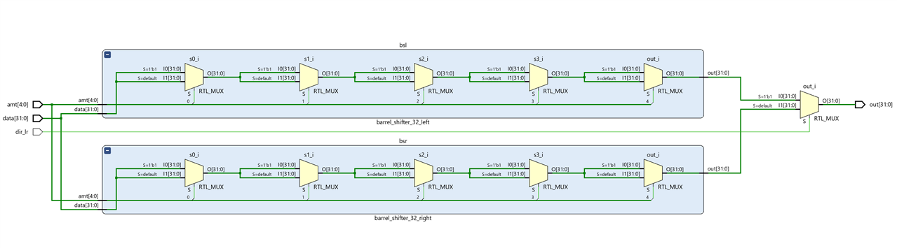
The code includes the previous right barrel shifter and adds a new one in the opposite direction to the left. Depending on the address signal dir_lr one or the other is selected.
Expanding the two barrel shifters we can see how this solution needs more multiplexers than the previous one.
Test bench
We can use a test-bench similar to the previous case but changing the instantiation of the unit under test, uut.
module barrel_shifter_32_multi_testbench;
    logic [31:0] data;
    logic [4:0] amt;
    logic [31:0] out;
    logic dir_lr;

    barrel_shifter_32_multi uut(.*);

    initial begin
        for (int i = 0; i < 32; ++i)
            begin
                data = 32'b1; amt = i; dir_lr = ROTATE_LEFT; #10;
            end
        for (int i = 0; i < 32; ++i)
            begin
                data = 32'b1; amt =i; dir_lr = ROTATE_RIGHT;  #10;
            end
        $stop;
    end

endmodule
Simulation
In the simulation we can see graphically how the offset affects the single bit at high.
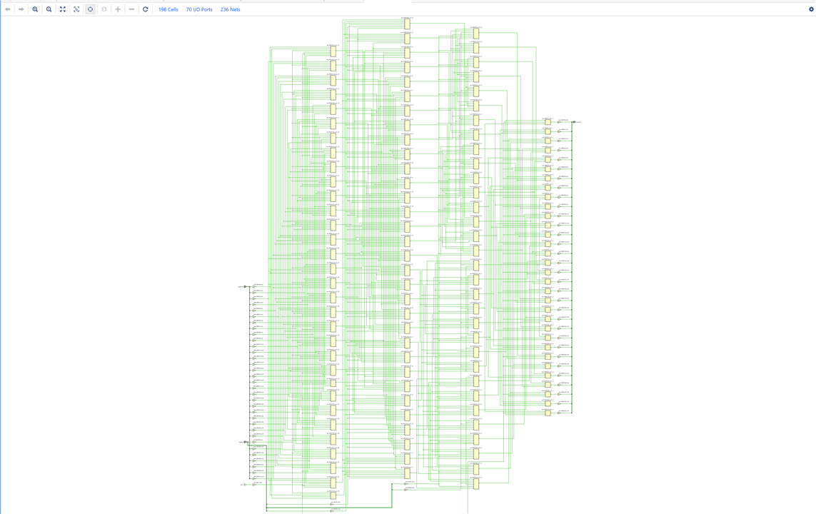
The synthesized design is similar to the previous one with 198 cells
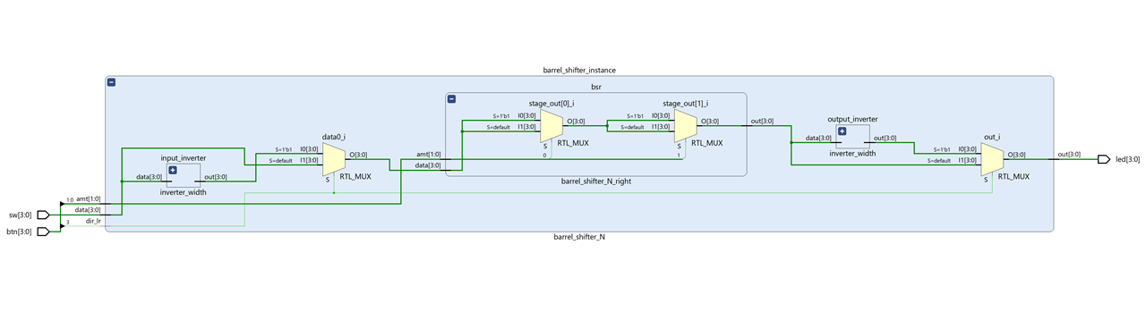
Parameterizable word width multifunction barrel shifter
Finally we are going to make a version with parameterizable data length.
In this parametrized barrel shifter the input width can be specified by a parameter N. The width of input will be 2^N
`timescale 1ns / 1ps
const logic ROTATE_LEFT = 1'b1;
const logic ROTATE_RIGHT = 1'b0;
// The width of input will be 2^N  ie N=5 width 32
module barrel_shifter_N #(parameter N=4) (
    input logic [2**N-1:0] data,
    input logic [N-1:0] amt,
    input logic dir_lr, // 1 rotate left, 0 rotate right
    output logic [2**N-1:0] out
);
    localparam WIDTH = 2**N;
    logic [WIDTH-1:0] out_right;
    logic [WIDTH-1:0] reversed_outr;
    logic [WIDTH-1:0] reversed_data;

    barrel_shifter_N_right #(.N(N)) bsr(.data((dir_lr == ROTATE_LEFT) ? reversed_data:data), .amt(amt) , .out(out_right));

    // reverse input circuit
    inverter_width #(.WIDTH(WIDTH)) input_inverter(.data(data), .out(reversed_data));
    //  reverse output circuit
    inverter_width #(.WIDTH(WIDTH))output_inverter(.data(out_right), .out(reversed_outr));

    // if rotate right use rotated output
    assign  out = (dir_lr == ROTATE_LEFT) ? reversed_outr:out_right;

endmodule

// rotates amt bits of data to the right staged implementation
//
module barrel_shifter_N_right #(parameter N = 4)(
    input logic [2**N-1:0] data,
    input logic [N-1:0] amt,
    output logic [2**N-1:0] out
);

    localparam WIDTH = 2**N;
    logic  [N-1:0][WIDTH-1:0] stage_out;

    generate
        genvar  stage ;
        assign stage_out[0] = amt[0] ? { data[0], data[WIDTH-1:1]} : data;
        for (stage = 1; stage < N ; ++stage)
        begin
            assign stage_out[stage] = amt[stage] ?
                {stage_out[stage-1][stage**2:0], stage_out[stage-1][WIDTH-1:2**stage]}
                : stage_out[stage -1];
        end
        assign out = stage_out[N-1];
    endgenerate

endmodule

// reverse 32-bit data
module inverter_width #(parameter WIDTH=32) (
    input logic [WIDTH-1:0] data,
    output logic [WIDTH-1:0] out
);
    // reverse a vector using right-to-left streaming with the default block size of 1 bit
    assign out = {<<{data}};
endmodule

module barrel_shifter_N_testbench;

    localparam N = 3;
    localparam WIDTH = 2**N;

    logic [WIDTH-1:0] data;
    logic [N-1:0] amt;
    logic [WIDTH-1:0] out;
    logic dir_lr;

    barrel_shifter_N #(.N(N)) uut(.*);

    initial begin
        for (int i = 0; i < WIDTH; ++i)
            begin
                data = 5; amt = i; dir_lr = ROTATE_LEFT; #10;
            end
        for (int i = 0; i < WIDTH; ++i)
            begin
                data = 5; amt =i; dir_lr = ROTATE_RIGHT;  #10;
            end
        $stop;
    end

endmodule
Since now the number of stages to shift the data is variable, we can use a generate block to generate the different necessary stages in a loop.
 generate
   genvar stage ;
   assign stage_out[0] = amt[0] ? { data[0], data[WIDTH-1:1]} : data;
   for (stage = 1; stage < N ; ++stage)
     begin
       assign stage_out[stage] = amt[stage] ?
         {stage_out[stage-1][stage**2:0], stage_out[stage-1][WIDTH-1:2**stage]}
         : stage_out[stage -1];
     end
   assign out = stage_out[N-1];
 endgenerate
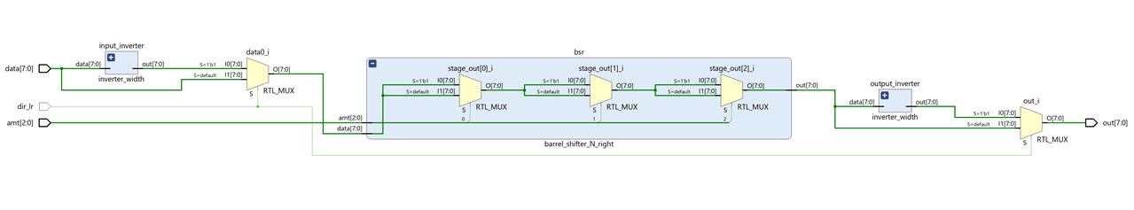
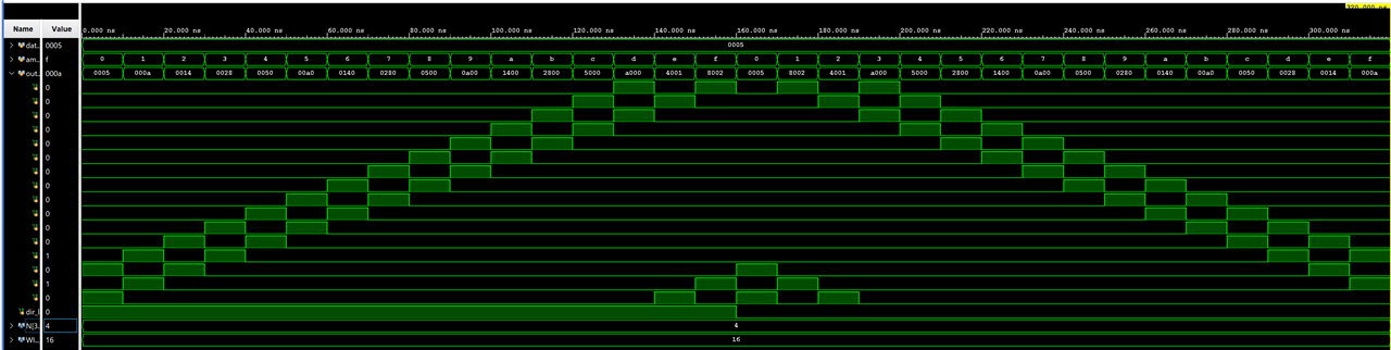
Simulation with N = 3, Word width = 8,
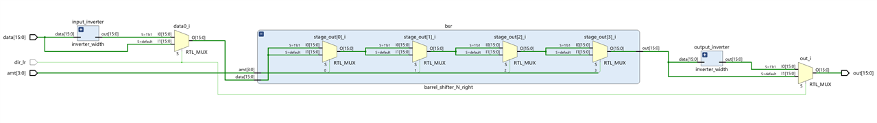
N = 4, Word width = 16 bits. 4 stages
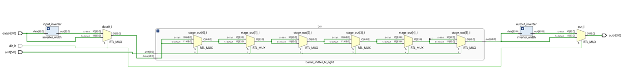
N = 6 Word width = 64 bits
Testing circuit with the Arty S7
To test the circuit we can use the four slide switches for the data signal, two pushbuttons switches for the amt signal, and the four discrete LEDs for the output.
A top-level HDL file is created to wrap the parametrizable barrel shifter circuit and maps its signals to the Arty S7 signals.
SystemVerilog code
`timescale 1ns / 10ps

module barrel_shifter_top_wrapper(
    input logic [3:0] btn,
    input logic [3:0] sw,
    output logic [3:0] led
);

    barrel_shifter_N #(.N(2)) barrel_shifter_instance(
        .data(sw[3:0]),
        .amt(btn[1:0]),
        .dir_lr(btn[3]),
        .out(led[3:0]));

endmodule
Constraint file
## This file is a general .xdc for the Arty S7-50 Rev. E

## Switches
set_property -dict { PACKAGE_PIN H14   IOSTANDARD LVCMOS33 } [get_ports { sw[0] }]; #IO_L20N_T3_A19_15 Sch=sw[0]
set_property -dict { PACKAGE_PIN H18   IOSTANDARD LVCMOS33 } [get_ports { sw[1] }]; #IO_L21P_T3_DQS_15 Sch=sw[1]
set_property -dict { PACKAGE_PIN G18   IOSTANDARD LVCMOS33 } [get_ports { sw[2] }]; #IO_L21N_T3_DQS_A18_15 Sch=sw[2]
set_property -dict { PACKAGE_PIN M5    IOSTANDARD SSTL135 } [get_ports { sw[3] }]; #IO_L6N_T0_VREF_34 Sch=sw[3]

## LEDs
set_property -dict { PACKAGE_PIN E18   IOSTANDARD LVCMOS33 } [get_ports { led[0] }]; #IO_L16N_T2_A27_15 Sch=led[2]
set_property -dict { PACKAGE_PIN F13   IOSTANDARD LVCMOS33 } [get_ports { led[1] }]; #IO_L17P_T2_A26_15 Sch=led[3]
set_property -dict { PACKAGE_PIN E13   IOSTANDARD LVCMOS33 } [get_ports { led[2] }]; #IO_L17N_T2_A25_15 Sch=led[4]
set_property -dict { PACKAGE_PIN H15   IOSTANDARD LVCMOS33 } [get_ports { led[3] }]; #IO_L18P_T2_A24_15 Sch=led[5]

## Buttons
set_property -dict { PACKAGE_PIN G15   IOSTANDARD LVCMOS33 } [get_ports { btn[0] }]; #IO_L18N_T2_A23_15 Sch=btn[0]
set_property -dict { PACKAGE_PIN K16   IOSTANDARD LVCMOS33 } [get_ports { btn[1] }]; #IO_L19P_T3_A22_15 Sch=btn[1]
set_property -dict { PACKAGE_PIN J16   IOSTANDARD LVCMOS33 } [get_ports { btn[2] }]; #IO_L19N_T3_A21_VREF_15 Sch=btn[2]
set_property -dict { PACKAGE_PIN H13   IOSTANDARD LVCMOS33 } [get_ports { btn[3] }]; #IO_L20P_T3_A20_15 Sch=btn[3]

## Configuration options, can be used for all designs
set_property BITSTREAM.CONFIG.CONFIGRATE 50 [current_design]
set_property CONFIG_VOLTAGE 3.3 [current_design]
set_property CFGBVS VCCO [current_design]
set_property BITSTREAM.CONFIG.SPI_BUSWIDTH 4 [current_design]
set_property CONFIG_MODE SPIx4 [current_design]

## SW3 is assigned to a pin M5 in the 1.35v bank. This pin can also be used as
## the VREF for BANK 34. To ensure that SW3 does not define the reference voltage
## and to be able to use this pin as an ordinary I/O the following property must
## be set to enable an internal VREF for BANK 34. Since a 1.35v supply is being
## used the internal reference is set to half that value (i.e. 0.675v). Note that
## this property must be set even if SW3 is not used in the design.
set_property INTERNAL_VREF 0.675 [get_iobanks 34]
Elaborated design
The barrel shifter in action
The four slide switches define the data, data signal, the two pushbuttons switches on the right define the shifting amount, amt signal, , the left pushbutton switch defines the shift direction, dir_lr signal, and the four discrete LEDs show the output, out signal.

SystemVerilog Study Notes Chapters
- Gate-Level Combinational Circuit
- RTL Combinational Circuit Operators
- RTL Combinational Circuit - Concurrent and Control Constructs
- Hex-Digit to Seven-Segment LED Decoder RTL Combinational Circuit
- Barrel Shifter RTL Combinational Circuit
- Simplified Floating Point Arithmetic. RTL Combinational Circuit
- BCD Number Format. RTL Combinational Circuit
- DDFS. Direct Digital Frequency Synthesis for Sound
- FPGA ADSR envelope generator for sound synthesis
- AMD Xilinx 7 series FPGAs XADC
- Building FPGA-Based Music Instrument Synthesis: A Simple Test Bench Solution
